Quick Look
Grade Level: 9 (9-11)
Time Required: 2 hours
(can be split into two 60-minute sessions)
Expendable Cost/Group: US $13.00 The breadboards, wires, wire strippers, resistors and multimeters can be re-used.
Group Size: 2
Activity Dependency: None
Subject Areas: Physical Science, Physics
NGSS Performance Expectations:

| HS-PS3-3 |
Summary
Students investigate circuits and their components by building a basic thermostat. They learn why key parts are necessary for the circuit to function, and alter the circuit to optimize the thermostat temperature range. They also gain an awareness of how electrical engineers design circuits for the countless electronic products in our world.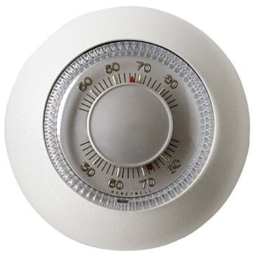
Engineering Connection
Circuits are pervasive in the modern engineered world. Most engineers have a good understanding of electricity and basic circuitry so as to better design everything from cars and houses, to cell phones and computers. Electrical engineers design the circuits that power our houses and appliances. Aerospace and mechanical engineers use their understanding of circuits to design control systems (such as anti-lock brakes), motors, amusement park rides, wave machines and space flight equipment. Other engineers design devices such as thermostats to reduce energy usage and waste.
Learning Objectives
After this activity, students should be able to:
- Describe the relationship of a programmable thermostat to energy conservation.
- Develop a model of the circuitry in a programmable thermostat.
- Describe how engineers use circuit diagrams to design a circuit.
- List the advantages of using a breadboard during circuit design.
Educational Standards
Each TeachEngineering lesson or activity is correlated to one or more K-12 science,
technology, engineering or math (STEM) educational standards.
All 100,000+ K-12 STEM standards covered in TeachEngineering are collected, maintained and packaged by the Achievement Standards Network (ASN),
a project of D2L (www.achievementstandards.org).
In the ASN, standards are hierarchically structured: first by source; e.g., by state; within source by type; e.g., science or mathematics;
within type by subtype, then by grade, etc.
Each TeachEngineering lesson or activity is correlated to one or more K-12 science, technology, engineering or math (STEM) educational standards.
All 100,000+ K-12 STEM standards covered in TeachEngineering are collected, maintained and packaged by the Achievement Standards Network (ASN), a project of D2L (www.achievementstandards.org).
In the ASN, standards are hierarchically structured: first by source; e.g., by state; within source by type; e.g., science or mathematics; within type by subtype, then by grade, etc.
NGSS: Next Generation Science Standards - Science
| NGSS Performance Expectation | ||
|---|---|---|
|
HS-PS3-3. Design, build, and refine a device that works within given constraints to convert one form of energy into another form of energy. (Grades 9 - 12) Do you agree with this alignment? |
||
| Click to view other curriculum aligned to this Performance Expectation | ||
| This activity focuses on the following Three Dimensional Learning aspects of NGSS: | ||
| Science & Engineering Practices | Disciplinary Core Ideas | Crosscutting Concepts |
| Design, evaluate, and/or refine a solution to a complex real-world problem, based on scientific knowledge, student-generated sources of evidence, prioritized criteria, and tradeoff considerations. Alignment agreement: | At the macroscopic scale, energy manifests itself in multiple ways, such as in motion, sound, light, and thermal energy. Alignment agreement: Although energy cannot be destroyed, it can be converted to less useful forms—for example, to thermal energy in the surrounding environment.Alignment agreement: Criteria and constraints also include satisfying any requirements set by society, such as taking issues of risk mitigation into account, and they should be quantified to the extent possible and stated in such a way that one can tell if a given design meets them.Alignment agreement: | Energy cannot be created or destroyed—it only moves between one place and another place, between objects and/or fields, or between systems. Alignment agreement: Modern civilization depends on major technological systems. Engineers continuously modify these technological systems by applying scientific knowledge and engineering design practices to increase benefits while decreasing costs and risks.Alignment agreement: |
Common Core State Standards - Math
-
Solve linear equations and inequalities in one variable, including equations with coefficients represented by letters.
(Grades
9 -
12)
More Details
Do you agree with this alignment?
-
Use units as a way to understand problems and to guide the solution of multi-step problems; choose and interpret units consistently in formulas; choose and interpret the scale and the origin in graphs and data displays.
(Grades
9 -
12)
More Details
Do you agree with this alignment?
-
Create equations that describe numbers or relationships
(Grades
9 -
12)
More Details
Do you agree with this alignment?
-
Rearrange formulas to highlight a quantity of interest, using the same reasoning as in solving equations.
(Grades
9 -
12)
More Details
Do you agree with this alignment?
International Technology and Engineering Educators Association - Technology
-
Students will develop an understanding of the relationships among technologies and the connections between technology and other fields of study.
(Grades
K -
12)
More Details
Do you agree with this alignment?
-
Energy resources can be renewable or nonrenewable.
(Grades
9 -
12)
More Details
Do you agree with this alignment?
-
Determine the best approach by evaluating the purpose of the design.
(Grades
9 -
12)
More Details
Do you agree with this alignment?
State Standards
Colorado - Math
-
Solve linear equations and inequalities in one variable, including equations with coefficients represented by letters.
(Grades
9 -
12)
More Details
Do you agree with this alignment?
-
Use units as a way to understand problems and to guide the solution of multi-step problems.
(Grades
9 -
12)
More Details
Do you agree with this alignment?
-
Create equations that describe numbers or relationships.
(Grades
9 -
12)
More Details
Do you agree with this alignment?
-
Rearrange formulas to highlight a quantity of interest, using the same reasoning as in solving equations.
(Grades
9 -
12)
More Details
Do you agree with this alignment?
Colorado - Science
-
Use appropriate measurements, equations and graphs to gather, analyze, and interpret data on the quantity of energy in a system or an object
(Grades
9 -
12)
More Details
Do you agree with this alignment?
Materials List
Each group needs:
- 1 breadboard (EXP 350 recommended, from online vendors; or RadioShack; or find used breadboards)
- 1(or more) LM35 temperature sensor chip (online from www.digikey.com; get extras in case students accidentally break one by setting up the circuit incorrectly.)
- 1 LM324AN operational amplifier integrated circuit (at RadioShack)
- 1 9-volt battery with battery connectors (or have a few for the class to share)
- 1 9-volt battery holder (optional, or have a few for the class to share)
- Ice
- Ziploc bag
- Thermostat Worksheet
- Breadboard and Circuit Diagram Basics Handout
For the entire class to share:
- 1 jumper wire kit (preferred since it is easier and reduces set-up time, at RadioShack), or each group needs 2 pieces of 1-inch wire, 2 pieces of 3-inch wire, and 5 pieces of 2-inch wire and electrical tape
- Small wire strippers (only needed if you are using insulated wire and not the jumper wire kit, to remove insulation at wire ends)
- Multiple ¼ watt resistors of various sizes from 500 Ohm up to 10K Ohm (100-piece kit and 500 piece kit at RadioShack)
- A few multimeters to make various measurements (such as Kelvin 50LE http://www.kelvin.com/ part # 990177)
Materials note: The breadboards, wires, wire strippers, resistors and multimeters can be re-used.
Worksheets and Attachments
Visit [www.teachengineering.org/activities/view/cub_housing_lesson02_activity1] to print or download.Pre-Req Knowledge
A familiarity with circuits in electricity, including the concepts of open and closed circuits.
Introduction/Motivation
Who can name some things that use a circuit — or multiple circuits? (Possible answers: Cell phones, radios, televisions, computers, video games, cars, houses, buildings, calculators.) Those are all great answers. Everything that plugs into a wall outlet or runs on batteries contains a circuit in order to operate. Can anyone give me a reason why an engineer would need to know about circuits? (Answer: To be able to design and create things that use electricity to operate.) That's right, many engineers use circuits in the design and manufacture of all the things we mentioned. More than any other type of engineer, electrical engineers primarily design using circuits. They are responsible for the design of most of the circuitry found in the everyday devices all around us, including computers and computer chips. However, many other engineers must have at least a basic understanding of circuits and how to create a simple circuit.
Today, we are going to investigate the circuit in a thermostat. Does anyone know what a thermostat is? A thermostat is a device installed in homes and buildings to regulate the temperature of an area of the building — such as a single room, a few rooms (a zone), or the entire building. They are designed in a way that it provides heat waste energy by converting electrical energy to thermal energy. Basically a thermostat works by determining the temperature in the immediate area of the sensor and converting that temperature into an electric signal. The thermostat is programmed to perform a chosen task based on that electric signal. The electric signal tells the thermostat to turn on or off a heater or air conditioner so as to change the temperature in the room.
We all want to conserve energy and make sure we are efficient in using energy in our homes, schools and places of work. Did you know that some thermostats are designed to help save energy? Most new homes and businesses use programmable thermostats that regulate the temperature of all or part of a building. These thermostats are useful in saving energy and can be programmed for many different settings. They are often set to not heat or cool a building during times when no people are using the building, since no one is present to benefit from the energy output. These times might be evenings in offices and schools, and daytimes at homes. Can you imagine how much energy we can save if we do not turn on the furnace or air conditioner when it is not needed?
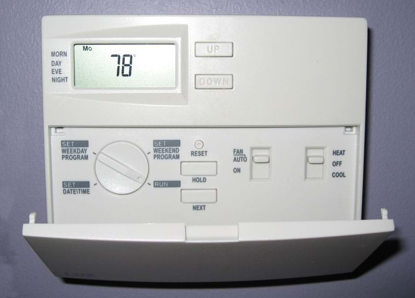
Programmable thermostats can also be set to direct the heater or air conditioner to maintain a temperature range throughout the time when people are using the building; you set a low temperature and an upper temperature that is comfortable for the building's inhabitants. If at any time the temperature at the thermostat sensor goes out of the set comfort range, the thermostat generates an electric signal to turn on either the heater to heat the room back up into the temperature range, or the air conditioner to cool the room down into the temperature range. The thermostat keeps the heater/cooler on until the temperature gets to the opposite side of the set comfort range, then sends another signal to turn it off, giving the air time to become cool or warm again before the cycle starts over.
For example, if a room goes below a set comfort temperature, the thermostat turns on the heater to warm up the room. The thermostat keeps the heater on until the temperature reaches the upper temperature boundary. Once the room temperature reaches that upper boundary, the thermostat signals to turn the heater off. Since the heater works more efficiently (saving energy) when it is not being turned on and off repeatedly, this ensures that the temperature must drop more than a degree or two before the heater is turned back on. So the benefit of having a programmable thermostat over a standard one, is that it allows you to set your own range of temperatures for the thermostat to keep the room at, rather than having the heater turn on and off repeatedly. With the more advanced programmable thermostat designs, you can program temperature ranges for different days of the week in advance, so you can accommodate differences in building use during weekdays and weekends.
As we mentioned earlier, circuits are used by different types of engineers. For example, circuits are important to mechanical engineers in the design of motors because most motors are run and maintained with a circuit. Mechanical engineers must be knowledgeable about circuits in order to effectively design and create motors to run the parts they design. Teams of engineers from with different specialties often work together to build everything from cars to roller coasters to medical instruments — devices that combine mechanical parts and electrical systems. Knowing the basic components of a circuit and how they fit and work together is important for engineers to understand if they are to design anything that uses electricity.
Today we are going to learn about the different components in a circuit and how to put them together to create a simple circuit, a thermostat. We are going to design a programmable thermostat, in which the user determines the temperature range s/he would like the room/building to remain in and the thermostat makes sure it does that in an energy-efficient way.
Procedure
Background
Circuits have become an essential part of our everyday lives. Circuits are found everywhere — in cars, TVs, computers, phones, homes, schools, etc. Their impact on our lives is immense and much of our society would not be the same without the circuit. Most every electrical circuit contains the same basic components — resistors, integrated circuits, capacitors and inductors. Each of these components performs a certain task (sometimes different components are combined to do the job of one of the other components) and are used by most engineers, especially those working with electricity or products that use electricity.
Thermostats are useful devices to regulate the temperature of a room, area or an entire building. They work by using a temperature sensor — generally an electronic chip designed to change its resistance depending on the temperature. As the temperature of the chip changes, the resistance of the chip changes and alters the voltage drop across the chip. The chip is internally calibrated to produce a linear relationship between the temperature and the voltage output of the sensor. After the sensor determines the temperature, the resulting electrical signal (output voltage) is sent into another portion of the circuit designed to interpret the incoming voltage and select an outcome based on the signal. This part of the circuit can be performed in many ways; however, the least complicated way is to use an operational amplifier (op amp).
Using an op amp permits the introduction of hysteresis into the circuit — or memory. In this activity, students take the output signal from the sensor and compare it to a predetermined voltage that is manually set. If the voltage from the sensor measures lower than the voltage the students set, indicating that the temperature sensor is reading a temperature that is colder than what we want it to be, the heater (an LED) turns on to "warm up" the room. Once the heater (LED) turns on, the hysteresis of the op amp forces the heater to stay on until the voltage goes above the second or high voltage set in the desired comfort range. This keeps the thermostat from rapidly turning the heater on and off if the temperature is hovering around the desired initial temperature. By forcing the heater to stay on until the second voltage, the circuit demonstrates path-dependence, which means that it remembers where it has been and uses that to inform what it will do next. It will not turn off after going above the low-set voltage because it "knows" that it just recently went below that mark. It forces the heater to stay on until the second voltage mark is passed.
The circuit the students create contains a LM35 temperature sensor, which has a linear relationship between the temperature of the sensor and the output voltage; the relationship is 10mV (0.01V) for every degree Celsius. Therefore, at room temperature (~20-23 °C), the LM35 should have an output voltage of 200-230mV (0.20-0.23 V). As the temperature rises or falls, the output voltage rises or drops 10mV (0.01 V) for each degree of temperature change.
Before the Activity
- If using insulated wire, cut it into sections for each group.
- Make copies of the Thermostat Worksheet and the Breadboard and Circuit Diagram Basics Handout.
With the Students
Part 1: How can you measure temperature electronically?
- Divide the class into groups of two or three students each.
- Distribute the materials to each group along with the worksheet and handout.
- If using the insulated wire, have students strip about 1/4 to 3/8 of an inch from both ends of each of the wires.
- Have students set up the circuit as shown in Part 1 of the worksheet using the breadboard, jumper wires, 9 V battery, and the LM35 Temperature Sensor chip. The circuit is shown in Figure 1. Reference the handout for additional information, especially clarification of the circuit diagram symbols and breadboards parts.
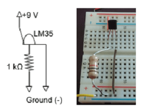
- Have students turn on the multimeters and set them up to measure voltage in mV. Have students measure the voltage across the 1 kΩ resistor. They should get a positive value around 0.23 V.
- Have students rub their hands together and touch the top of the LM35 sensor. Note what happens to the voltage reading.
- Have students measure the temperature (ºC) and voltage (V) of the room and their palm using a thermometer and the circuit they just built. Record data in the space provided in the Thermostat Worksheet.
- Using their data, students should develop an equation to determine the voltage across the 1 kΩ resistor in terms of temperature (ºC) assuming a linear relationship.
Part 2: How can you "set" the thermostat?
- Set the thermostat in cooling mode. Instruct students to choose a "set" temperature that is lower than their palm temperature, but higher than the room temperature.
- Determine the LM35 voltage output corresponding to the set temperature.
- Have students divide the 9 V supplied by the battery so that part of the circuit equals the LM35 output voltage for their desired temperature. Do so by moving the 1 kΩ resistor (R2) over and combining it with another (R1) as shown in Figure 2.
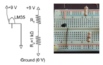
- Have students answer the questions under Part 2 (question 5) in the worksheet to identify the relationship between current and voltage.
- Also in their worksheets, tell students to determine an equation to quantify the value of R1.
- After obtaining an equation for R1, plug in the known values (VBat=9 V, R2=1 kΩ, V2 set point) in order to determine the value needed for R1.
Part 3: Does the light turn on when it is supposed to?
- Have students connect the LM35 sensor and voltage divider to an operational amplifier (LM324). Add the LM324, 2 kΩ resistor (R3), light emitting diode (LED) and connections to their breadboard as shown in the worksheet and in Figure 3 below.
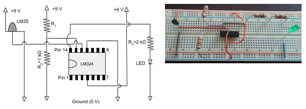
- Instruct students to connect the 9 V battery (see the following steps) to the circuit to measure the voltage across R2.
- Have students place the battery in the battery holder, or tape the ends of the two pieces of 3-inch wire to both the positive and negative terminals of the battery.
- Connect the wire coming from the positive terminal (denoted with a "+" on the side of the battery that the positive terminal is on) to the power row on the breadboard.
- To complete the circuit, connect the wire coming from the negative terminal (denoted with a "–" on the side of the battery) to the ground row on the breadboard.
- Remind students to disconnect the battery between measurements.
- Have students continue to follow in their worksheets to answer the questions provided.
Part 4: Can a thermostat save energy?
- Have students answer the questions in their worksheets to redesign their thermostats for the case when nobody is home.
Part 5: Can you use the circuit for a heating circuit?
- Have students adjust their circuit so it accommodates for heating by following instructions in their worksheets.
Part 6: Can "on" and "off" be at different temperatures?
- Have students use their heating circuit to measure the temperature and voltage when it turns on and turns off and record in their worksheets.
- Have one student in each team continue to measure the voltage from the output of the temperature sensor while the others cool the temperature sensor using a Ziploc bag containing ice.
- Have students add one resistor (R4) to create different "on" and "off" points for the heating circuit. The heating circuit should resemble that in Figure 4 below.
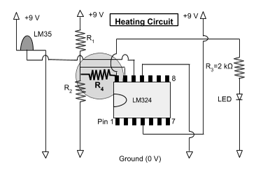
- Have students measure the voltage drop from pin 14 to ground when the LED is on to later figure out the value of R4.
- Following along in their worksheets, direct students to develop an equation for R4 using Ohm's Law (V=IR) and properties of series circuits.
- Using the appropriate R4, have students test the circuit and comment on how it behaves.
Part 7: Reflection
- Conclude by leading a class discussion to review the worksheet answers using the Thermostat Worksheet Answer Key.
- To further test students' comprehension, ask them how they would make the thermostat hysteresis work in reverse, so that the circuit turns on at the higher temperature and turns off at the lower temperature — like an air conditioner, instead of a heater.
- Have students complete the handout Programmable Thermostat Energy Savings Worksheet. This allows students to calculate potential energy savings by using a programmable thermostat.
Vocabulary/Definitions
Breadboard: A reusable solderless tool used to create a temporary (usually a prototype) circuit to experiment with until a more permanent circuit is created.
Conductor: A material that allows charges to move easily, such as copper wire.
Electric current: The flow of electric charge through an electrical circuit or conductor.
Electrical circuit: A collection of circuit elements (resistances, inductances, capacitances, etc.) connected in closed paths by conductors.
Hysteresis: An electric circuit that is path-dependent and, thus, has memory.
Hysteresis band: The difference in voltage between the turn on and turn off points in an electrical circuit using hysteresis.
Integrated circuit (IC): Several circuit elements that are manufactured together onto a single chip by a sequence of processing steps.
Operational amplifier (op-amp): An integrated circuit that contains multiple resistors and capacitors. Op-amps have many practical applications in engineering instrumentation.
Parallel: Two or more circuit elements are in parallel if they are connected to the same node or junction of the circuit and have the same voltage drop across their terminals.
Resistor: A circuit element that resists electric current and dissipates energy in the form of heat.
Series: Two or more circuit elements are in series if the same current flows through them.
Voltage: A measure of the potential energy of an electrical field to cause an electrical current in a conductor
Assessment
Pre-Activity Assessment
Class Discussion Question: Ask the students and discuss as a class:
- Why might it be a good idea to be able to control at which temperatures a heater and/or air conditioner turns on and off?
Activity Embedded Assessment
Worksheet: Have students complete the Thermostat Worksheet; review their answers to gauge their mastery of the subject.
Post-Activity Assessment
Worksheet Discussion: Review and discuss the worksheet answers, provided in the Thermostat Worksheet Answer Key, with the entire class. Use students' answers to gauge their mastery of the subject.
In Reverse: Have students either brainstorm or research ways to allow the thermostat hysteresis work in reverse, so that the circuit turns on at the higher temperature and turns off at the lower temperature — like an air conditioner, instead of a heater. To do this, the students would rewire the circuit to turn on and off at different temperatures.
Safety Issues
- Working with electricity is always dangerous. To make sure that a component does not overheat, remind students to double-check their circuit with the circuit diagram and image provided on the worksheet before connecting the circuit to the battery.
- Attention to detail is important. Remind students to take care to make sure the components are placed where they should be. The wrong connections to ground and/or power can cause these chips to overheat, smoke, and (potentially) become permanently damaged.
Troubleshooting Tips
Make sure students do not leave the battery connected to the breadboard if they are not actively taking a measurement, debugging or observing the circuit. Keeping it unconnected most of the time prolongs the life of the battery and ensures that the circuit components do not get too hot by being "left on" for a while.
If a team's circuit is not working, disconnect the breadboard wires coming from the battery and double-check the circuit diagram and circuit. Make sure that the pins from the LM35 and LM324AN are connected and oriented correctly. If everything looks good, reconnect the battery and debug the circuit using the multimeter. Check the input and ground pins of the temperature sensor and the LM324AN to make sure they are connected properly. The multimeter should read 9 volts (or close to that) for the input on the temperature sensor; the ground for both should read zero volts (or close to that). The input of the LM324AN should be the same as the output of the temperature sensor. Also check the connections to the LED; make sure there is an input when there should be one, and that the ground pin of the LED reads zero volts.
LEDs can easily burn out if they are left on too long, or if too large of a current is sent through them. This is why the output from the LM324AN goes through a resistance before reaching the LED. If a circuit is not working, and everything else seems to be in the correct place, try a different LED.
Make sure that none of the resistors touch another resistor, which makes those two resistors in series and thus changes the value of the resistance, and consequently the voltage going through that section of the circuit.
Activity Extensions
Have students research hysteresis. Find out what it means, how this circuit uses hysteresis and other examples of hysteresis.
Have students research where else hysteresis shows up. Have them prepare a paragraph describing the phenomenon they discover and how it displays hysteresis. Also have them compare it to the circuit they have just built. How are they similar? How are they different?
Activity Scaling
- For students with a better understanding of circuit analysis, have them research the formulas used to determine the resistances needed to set the on/off points (Kirchhoff's voltage and current laws, Ohm's Law, etc.).
Subscribe
Get the inside scoop on all things TeachEngineering such as new site features, curriculum updates, video releases, and more by signing up for our newsletter!More Curriculum Like This

Students are introduced to several key concepts of electronic circuits. They learn about some of the physics behind circuits, the key components in a circuit and their pervasiveness in our homes and everyday lives.
References
Hambley, Allan R., Electrical Engineering: Principles and Applications, Third Edition. Upper Saddle River, NJ: Pearson Education Inc., 2005.
Copyright
© 2007 by Regents of the University of ColoradoContributors
Tyler Maline; Lauren Cooper; Malinda Schaefer Zarske; Denise W. Carlson; Aaron OsowieckiSupporting Program
Integrated Teaching and Learning Program, College of Engineering, University of Colorado BoulderAcknowledgements
The contents of this digital library curriculum were developed under a grant from the Fund for the Improvement of Postsecondary Education (FIPSE), U.S. Department of Education and National Science Foundation GK-12 grant no. 0338326. However, these contents do not necessarily represent the policies of the Department of Education or National Science Foundation, and you should not assume endorsement by the federal government.
Last modified: August 30, 2020


User Comments & Tips