
Slow the Cylinder: Experimenting with Shock Absorber Springs
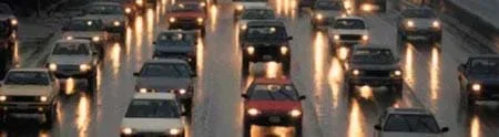 The springs in shock absorbers provide more comfortable rides for passengers.Copyright Oak Ridge National Laboratory http://www.ornl.gov/info/ornlreview/v32_2_99/driving.htm
Students learn why shock absorbers are necessary on vehicles, how they dampen the action of springs, and what factors determine the amount of dampening. They conduct an experiment to determine the effect of spring strength and port diameter on the effectiveness of a shock absorber. Using a syringe, a set of springs, and liquids of different viscosities, students determine the effects of changing pressures and liquids on the action of a model shock absorber. They analyze their data through the lens of an engineer.
Thanks to engineers, springs have been used to soften the ride for passengers since the days of horse carriages. As automobiles came into existence, the greater weight and speed of our vehicles required that the bouncing action of springs (oscillation) be controlled. Shock absorbers were invented to control the vertical acceleration of the wheels as they traveled over road bumps. As research evolved, engineers found ways to fine tune the amount of spring dampening to match the vehicle to the road conditions and its intended use. And vehicles are not the only use for shock absorbers! Engineers design buildings in earthquake zones to include a type of absorber that reduces damage (to people or sensitive scientific equipment, for example) when the ground shakes.
After this activity, students should be able to:
- Explain the purpose for a shock absorbing device on vehicle suspensions.
- Describe the variables that affect the dampening ability of shock absorbers.
- CCSS.Math.Content.6.SP.B.4 Display numerical data in plots on a number line, including dot plots, histograms, and box plots.
Grade 6
Do you agree with this alignment? - CCSS.Math.Content.6.SP.B.5 Summarize numerical data sets in relation to their context, such as by:
Grade 6
Do you agree with this alignment? - CCSS.Math.Content.6.SP.B.5a Reporting the number of observations.
Grade 6
Do you agree with this alignment? - CCSS.Math.Content.6.SP.B.5b Describing the nature of the attribute under investigation, including how it was measured and its units of measurement.
Grade 6
Do you agree with this alignment? - CCSS.Math.Content.6.SP.B.5c Giving quantitative measures of center (median and/or mean) and variability (interquartile range and/or mean absolute deviation), as well as describing any overall pattern and any striking deviations from the overall pattern with reference to the context in which the data were gathered.
Grade 6
Do you agree with this alignment?
- The process of experimentation, which is common in science, can also be used to solve technological problems.
Grades 3-5
Do you agree with this alignment? - STEL-2A Illustrate how systems have parts or components that work together to accomplish a goal.
Grades -1-2
Do you agree with this alignment? - STEL-8A Analyze how things work.
Grades -1-2
Do you agree with this alignment?
- Developments in physics affect society and societal concerns affect the field of physics.
Grades 9-12
Do you agree with this alignment?
- MS-ETS1-3 Analyze data from tests to determine similarities and differences among several design solutions to identify the best characteristics of each that can be combined into a new solution to better meet the criteria for success.
Grades 6-8
This resource focuses on the following Three Dimensional Learning aspects of NGSS:
Science & Engineering Practices- Analyze and interpret data to determine similarities and differences in findings.Do you agree with this alignment?
Disciplinary Core Ideas- There are systematic processes for evaluating solutions with respect to how well they meet the criteria and constraints of a problem.Do you agree with this alignment?
- Sometimes parts of different solutions can be combined to create a solution that is better than any of its predecessors.Do you agree with this alignment?
- Although one design may not perform the best across all tests, identifying the characteristics of the design that performed the best in each test can provide useful information for the redesign process—that is, some of the characteristics may be incorporated into the new design.Do you agree with this alignment?
Do you agree with this alignment? - Analyze and interpret data to determine similarities and differences in findings.
Each group needs:
- 20-ml syringe
- clear plastic cup (see Figure 3)
- water, 8 oz (237 ml)
- regular soda, 8 oz (237 ml)
- canola oil, 8 oz (237 ml)
- 2 small springs with different spring constants (stiffness) that are each able to fit in the syringe cylinder
- stopwatch
- duct tape
- pin, to poke a hole in the tape
- Slowing the Cylinder Worksheet (PDF), one per person
Have you ever ridden a bicycle on a very rough trail? How did you keep from bouncing off the bike? (Listen to student responses. Possible answer: We used our knees and elbows as springs to absorb the shock of the bumps.) That is the reason we have springs on our vehicles—so that passengers do not feel every bump in the road. In the past, more than 100 years ago, carriages pulled by horses also used springs to make more comfortable rides for passengers.
When cars were invented, they soon became faster and heavier than horse-drawn carriages. Stronger springs were needed to cushion passengers from the roads, which were uneven and full of ruts. What the drivers soon found out, though, was that when the tires lifted off the road from a bump (known as vertical acceleration), the vehicle lost traction and the car continued to bounce up and down until the energy in the spring was dissipated. This oscillation can be compared to a pendulum that continues to swing until all its potential energy is dissipated by friction.
Engineers discovered that the use of a shock absorber with a controlled action at each wheel would dampen the movement of the spring and convert the bouncing action to heat. Using shock absorbers, not only was the ride smoother, but the wheels remained in contact with the road surface, which prevented loss of control and resulted in fewer accidents.
Shock absorbers make our vehicles (including bicycles, now!) safer by maintaining smoother rides and keeping the wheels on the road surface. Matching the correct absorber to the type of road and vehicle requires knowledge of the vehicle's weight, speed and road conditions. Engineers are continually striving to improve the ride and increase safety.
Today, we will be working as engineers to determine the impact of different variables on the effectiveness of shock absorbers!
Before the Activity
- Gather materials and make copies of the Slowing the Cylinder Worksheet (PDF), one per student.
- Divide the class into teams of two students each.
With the Students: Background Information
Introduce students to the following information regarding a commonly used approach to shock absorption:
Fluid friction, for example the flow of fluid through a narrow orifice (hydraulics), provides for the vast majority of automotive shock absorber designs. An advantage of this type of shock absorber is that by using special internal valving, the shock absorber may be made relatively soft to compression (allowing a soft response to a bump) and relatively stiff to extension, controlling "rebound," which is the vehicle response to energy stored in the springs.
Similarly, a series of valves controlled by springs can change the degree of stiffness according to the velocity of the impact or rebound. Specialized shock absorbers for racing purposes may allow the front end of a dragster to rise with minimal resistance under acceleration, then strongly resist letting it settle, thereby maintaining a desirable rearward weight distribution for enhanced traction. Some shock absorbers allow tuning of the ride via control of the valve by a manual adjustment provided at the shock absorber. In more expensive vehicles, the valves may be remotely adjustable, offering the driver control of the ride—at will—while the vehicle is operated! The ultimate control is provided by dynamic valve control via computer in response to sensors, giving both a smooth ride and a firm suspension when needed. Many shock absorbers contain compressed nitrogen, to reduce the tendency for the oil to foam under heavy use. Foaming temporarily reduces the damping ability of the unit. In heavy-duty units used for racing and/or off-road use, a secondary cylinder may be connected to the shock absorber to act as a reservoir for the oil and pressurized gas. Another variation is the magneto rheological damper, which changes its fluid characteristics through an electromagnet.
In today's activity, we will extrapolate these ideas by using a syringe, spring and fluid set-up to model a shock absorber. Then, we will investigate how well different variables help our model "shock absorbers" to control rebound by slowing extension!
With the Students—Experiment
Set the context of the experiment by asking the students: What controls shock absorber cylinder speed more: spring pressure or orifice size?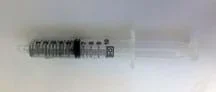 Figure 1. A spring inside a syringe, capped with a plunger.Copyright 2011 Massiel Puentes Reyes
In today's experiment, you will work with a partner to conduct two sets of tests with three liquids of varying viscosities in order to determine the best design for a "shock absorber," which will be modeled with a syringe, spring and plunger set-up (see Figure 1).
- In the first test, you will determine the difference in time to extend the plunger by comparing two different springs. You will find out if the stiffness (or spring constant) of a spring has an effect on how quickly a shock absorber returns to its normal position.
- During the second test, you will change the size of the orifice (hole leading out of the syringe, aka cylinder) to see if it makes a difference in the time to extend the plunger.
Then, you will analyze your collected data and predict the best design for a model shock absorber.
Test 1. Original Orifice Size
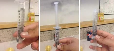 Figure 2. Place a spring inside the syringe (left), fill it with enough water to cover the spring and top it with the plunger (middle), then flip it over to push out any air in the syringe (right).Copyright 2011 Massiel Puentes Reyes. Used with permission.
- Insert one of the springs inside the syringe, as shown in Figure 2 (left).
- While holding your finger over the bottom hole of the syringe, pour water into the syringe until the spring is completely submerged. Place the plunger on top of the syringe, as shown in Figure 2 (middle).
- Ideally, no air should be in the syringe when it is assembled. Flip the syringe and plunger set-up upside down, and push out any air inside the syringe, as shown in Figure 2 (right).
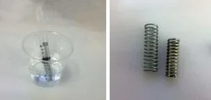 Figure 3. Spring and plunger set-up, submerged in water (left). Two different springs (right).Copyright 2011 Massiel Puentes Reyes. Used with permission.
- Place the syringe and plunger set-up into a clear plastic cup that is partway filled with water, as shown in Figure 3 (left). When conducting all tests, keep the bottom of the syringe in the liquid to avoid drawing air into the system.
- Push down on the plunger, compressing the spring until only 2 ml of water remain in the syringe.
- Get your stopwatch ready. Then, let go of the plunger, and time how long (in seconds) it takes for the piston to return to its fully extended position. Record the time in the correct data table on your worksheets.
- Repeat steps 1-6 with a different spring (see Figure 3 [right]). Record the results in the correct data table on your worksheets.
Test 2. Reduced Orifice Size
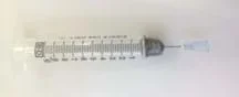 Figure 4. Create a smaller orifice.Copyright 2011 Massiel Puentes Reyes. Used with permission.
- Place two layers of duct tape over the syringe hole to seal it completely. Test your seal for leaks, and reapply the tape, if necessary. Then, use a pin to carefully poke a small hole in the tape to create a tiny orifice (see Figure 4).
- Repeat steps 1-7 in the procedure above (Test 1. Original Orifice Size) and record the data on your worksheets.
Test 3. Original Orifice Size with Soda
Repeat steps 1-7 in the procedure above (Test 1. Original Orifice Size) with regular soda instead of water, and record the data on your worksheets.
Test 4. Original Orifice Size with Oil
Repeat steps 1-7 in the procedure above (Test 1. Original Orifice Size) with canola oil instead of water, and record the data on your worksheets.
- compression cycle
- Occurs as a piston moves downward, forcing the fluid through a small orifice.
- dampening
- A process that controls unwanted spring motion.
- dependent front suspension
- A suspension with a rigid front axle that connects the front wheels. Common on trucks, dependent front suspensions have not been used in mainstream cars for years.
- extension cycle
- Occurs as a piston moves toward the top of the pressure tube, allowing the fluid to return to the chamber. A typical car or light truck has more resistance during its extension cycle than its compression cycle.
- independent front suspension
- A suspension in which the front wheels are allowed to move independently.
- shock absorber
- A device that controls unwanted spring motion.
Pre-Activity Assessment
Prediction: Ask students to predict: What controls shock absorber cylinder speeds more: spring pressure or orifice size? Solicit, integrate and summarize student responses.
Activity Embedded Assessment
Worksheet: As students conduct the experiment, have them complete the data tables on page 1 of the Slow the Cylinder Worksheet (PDF).
Graphing: Have students create a bar graph of their results, and use their graphs when answering the investigating questions.
Post-Activity Assessment
Reflection: Have students complete the reflection questions on page 2 of the Slow the Cylinder Worksheet (PDF). Review their answers to gauge their mastery of the concepts.
Have students calculate the spring constants of each spring using Hooke's law: F=kx, where k is the spring constant, x is the distance of spring displacement, and F is the force applied to the spring. Then, using their data, have students reflect on the relationship between spring constants and the correlating effectiveness of shock absorption.
Harris, William. How Car Suspensions Work. HowStuffWorks, Inc. Accessed May 17, 2010. http://auto.howstuffworks.com/car-suspension2.htm
Contributors
Cliff Orgaard; Marissa H. Forbes
Supporting Program
Center for Compact and Efficient Fluid Power RET and ERC, University of Minnesota
Acknowledgements
The contents of this digital library curriculum were developed under National Science Foundation grant no. EEC 0540834. However, these contents do not necessarily represent the policies of the National Science Foundation, and you should not assume endorsement by the federal government.
Copyright
2013 by Regents of the University of Colorado; original © 2011 University of Minnesota