Quick Look
Grade Level: High school
Time Required: 2 hours 30 minutes (wild guess!)
Subject Areas: Computer Science, Measurement, Problem Solving, Science and Technology
Maker Challenge Recap
The goal of this maker challenge is to demystify sensors, in particular the ambient light sensor, and to map its readings visually. In today’s world, we make sense of the environment around us by filling it with sensors, and we use output devices to display real-time data in a meaningful way. Take any smartphone as an example. Aside from the embedded camera and microphone, a number of other sensors collect a wide range of data. Depending upon the model, these sensors may collect data on proximity, motion, ambient light, moisture, compass, and touch. Some of these data are directly visualized through an app, while many operate internally and without a user interface, just below the surface of the screen. In order to become more familiar with the technology that we use (and often take for granted) on a daily basis, your challenge is to use the engineering design process as you assemble a light sensor circuit, observe its readings using the Arduino Serial Monitor, and then create your own unique visualization by interfacing with the Processing software. Students learn how to use calibration and smoothing to capture a better picture of the data. Afterwards, they share their visualizations with the entire class. The time required for this challenge depends on students’ prior knowledge of Arduino and Processing software. Background resources for beginners help students get up to speed on microcontroller hardware and offer additional challenges for intermediate and advanced users.
Maker Materials & Supplies
Hardware
- Option 1: Arduino Uno
- USB cable
- breadboard
- photoresistor (additional/alternative sensors may be used for challenges)
- 10k (Ω) Ohm resistor
- jumper cables (3+)
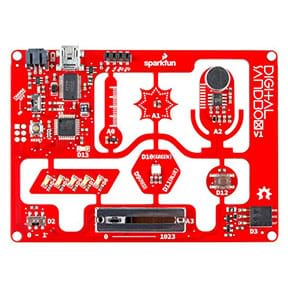
- Option 2: Arduino boards with built-in sensors
- SparkFun Digital Sandbox
- Adafruit Circuit Playground at Adafruit
Software
Worksheets and Attachments
Visit [www.teachengineering.org/makerchallenges/view/nyu2-2298-sensors-visualization-data-arduino-circuit-challenge] to print or download.Subscribe
Get the inside scoop on all things Teach Engineering such as new site features, curriculum updates, video releases, and more by signing up for our newsletter!More Curriculum Like This

Students learn about the first attempts at machine learning and specifically about the perceptron model—a simplified model of a biological neuron.

Students learn more about how color sensors work, reinforcing their similarities to the human sense of sight. This lesson and its associated activity enable students to gain a deeper understanding of how robots can take sensor input and use it to make decisions via programming.

As a part of the research and revise step of the Legacy Cycle, this lesson provides students with information they will need later on to be able to average pixels to simulate blurring in the peripheral plane of vision. Students learn why image color becomes important as we distort the outer boundari...

This is a series of short activities that introduce students to physical computing, where they will use a basic breadboard, an Arduino Uno, and components to code and run a single and double LED, a buzzer, and a touch sensor. After successfully coding and wiring the individual components, they have ...
Kickoff
Have you ever wondered about the hidden sensors in your cell phone and how they work? (Ask students to name them and describe their functions. Expect students to mention light sensors, touch sensors, GPS, etc. See Gizmodo field guide for more examples.)
How can we measure light? How does a light sensor (photocell/photoresistor) work? (Have students discuss ideas. See Adafruit tutorial for background on photocells.)
Likewise, how can we manipulate light, for example the pixels on a screen? (Have students discuss ideas. See Processing tutorials for background: Coordinate System and Shapes and Color.)
How can we create a unique visualization based on real-time data? (Students might be familiar with one common example—audio visualizers such as Windows Media Player. Take a look at a few examples, such as this four-minute YouTube video.) What is the input? What is the output? How are they linked?
The answers to all of these questions lie at the core of digital signal processing. No matter what sensor you are reading, it generates an input signal. In Arduino, the minimum value of an input signal is 0 and the maximum value is 1023. We can map this accordingly to an output.
input signal → Processing (map) → output signal
For example, if your phone's screen brightness is set to auto-adjust, the ambient light sensor (input) inversely affects your screen’s brightness (output); that is, the brighter the ambient light in the room, the darker your screen becomes, and vice versa.
In Processing, the grayscale value of pixels on the screen range from 0 (no light/black) to 255 (full light/white). Therefore, we need to map a domain of 1024 values (0→1023) to an inverse range of 256 values (255→0). Both Arduino and Processing feature a map function to do this for you:
map(value, fromLow, fromHigh, toLow, toHigh)
What would be the appropriate mapping in this case?
[Answer: map(brightness, 0, 1023, 255,0) ]
To confirm this, we’ll try out brightness demo later.
Resources
- Refer to the Engineering Design Process hub on Teach Engineering to guide your students through the challenge. For design process documentation, utilize the Engineering Design Process Notebook.
- To learn more about the sensors involved in your phone, read https://gizmodo.com/all-the-sensors-in-your-smartphone-and-how-they-work-1797121002
- Background reading on light sensors (photoresistors/photcells): https://learn.adafruit.com/photocells/overview
- Calibration Tutorial by Adafruit: https://learn.adafruit.com/calibrating-sensors/why-calibrate
- Drawing basic shapes & using color in Processing: https://processing.org/tutorials/coordinatesystemandshapes/#simple-shapes and https://processing.org/tutorials/color/
- Daniel Shiffman’s Coding Train YouTube channel: https://www.youtube.com/user/shiffman/playlists?sort=dd&view=50&shelf_id=2
- Serial Communication: https://learn.sparkfun.com/tutorials/terminal-basics/arduino-serial-monitor-windows-mac-linux
- ITP Lab: Serial Output from an Arduino to Processing: https://itp.nyu.edu/physcomp/labs/serial-output-from-an-arduino/
Maker Time
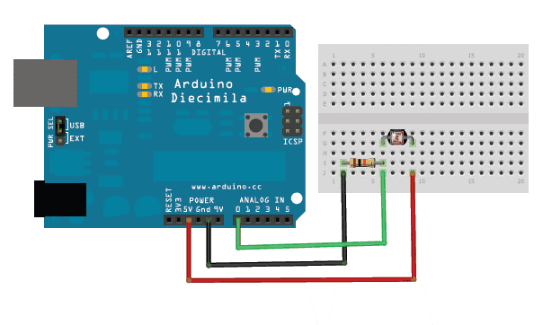
- Arduino Uno Users: Assemble the photocell circuit from the Adafruit Tutorial, also see Figure 1 (photocell, 10k Ω resistor, 3 wires).
*Tips
- Use a rubber band or cable ties to attach the Arduino to the breadboard.
- Light sensors are non-polar; it does not matter which leg the power or sound is connected to.
- If in a very well-lit area, you can substitute the 10k Ω resistor for a 1k Ω resistor.
- If using the Digital Sandbox or Circuit Playground, identify which pin to which the light sensor is connected.
- Test the circuit via Serial Monitor in the Arduino app.
Open File → Examples → Basics → AnalogReadSerial
Upload the program to your Arduino and open the Serial Monitor. (Refer to the Serial Communication tutorial if you are unfamiliar with the Serial Monitor.)
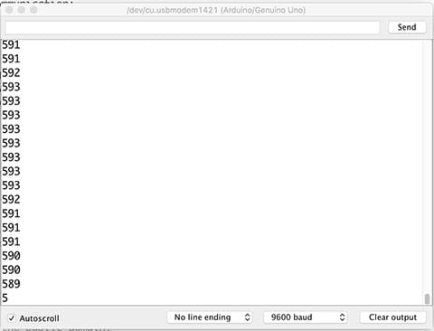
Expect to see numbers between 0 and 1023 appear in the Serial Monitor, as in shown Figure 2.
If so, place your hand over the sensor, what happens to the numbers?
If not, debug your circuit.
Digital Sandbox/Circuit Playground: Use any of the available analog inputs.
- Send Data to Processing & Visualize
As necessary, refer to Tom Igoe’s ITP Lab for this part.
The essential part is that you upload File → Examples → Communication → Graph to the Arduino and make sure that you see data appear in the Serial Monitor. Notice that your number range is smaller now, only 0 → 255. Why is this? (Hint: see code.)
Now comes the important part: close the Serial Monitor. Notice the Graph example includes code for Processing and Max/MSP. Copy the Processing code and paste directly into the Processing app. Change the opening of the multi-line comment /* into a single line comment // and delete the closing */ or simply use the Graph.pde example provided.
In Processing, run Graph.pde and expect to see a list of serial ports in the console. Your list will be vary, depending upon what other devices are connected to your computer. Figure 3 shows an example of a serial ports list.

Your Processing canvas is most likely blank at this point and you might receive an error message, which is completely normal. This is because you need to select the Arduino’s serial port as your input for the sketch to work correctly. Start counting each port from 0 until you reach one that ends with usbmodem. In Figure 3, Bluetooth is port 0 and the Arduino is port 1. Insert the correct number into the following line of code in the setup function:
myPort = new Serial(this, Serial.list()[number], 9600);
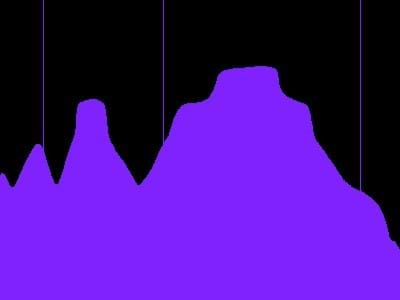
Now, run the program again and expect to see a live graph of your sensor’s data (see Figure 4)!
Try moving your hand to find the minimum and maximum value of your sensor. If you cannot approach a minimum of 0 or a maximum of 1023, calibrate the sensor. You might also notice random spikes in your data, and a solution exists for this as well.
- (optional) Calibrate and Smooth
Although it is not mandatory, you get a better overall light (or any) sensor reading if you calibrate it correctly and smooth its signal. Do this in Arduino, not Processing. The following examples demonstrates each algorithm.
- Arduino: File → Examples → Analog → Calibration
The big idea is to find the minimum reading and maximum reading of the sensor and then map it to the number range that you are looking for. You could use 0→1023 or shrink it to a smaller range such as 0→255.
- Arduino: File→ Examples → Analog → Smoothing
This example uses arrays, but that is not required. The big idea is to average your readings by summing a series of consecutive readings and dividing by the total. For example, average every 10 readings. Keep in mind that this slows down the pace of your readings by a factor of 10 (which can be a good thing, depending upon how quickly you want to receive readings).
- Try out the lightMapping demo
The following demo shows how to map sensor readings to different aspects of an animation in Processing. If you are new to Processing, now is a good time to familiarize yourself with the Shapes and Color tutorials on Processing.
- background(inByte);
Demonstrates how to map sensor readings to background color. This demo uses grayscale, but it can be easily changed to RGB or HSB.
- ellipse(width/2, height/2, inByte, inByte);
Demonstrates how to map sensor readings to the size of an ellipse’s radius. Try modifying the demo to work with different shapes.
- ellipse(inByte, height/2, 25,25);
Demonstrates how to map sensor readings to the position of an ellipse. Try modifying the demo to work with different shapes and move along different axes.
- Create your own unique visualization!
Now it’s your turn to be creative and find a unique way to visualize your sensor’s readings.
If you are looking for inspiration or more background information, plenty of free resources exist. Processing has some great text tutorials and if you like video tutorials, take a look at Daniel Shiffman's YouTube channel, The Coding Train, with a series called Learning Processing, which takes you from absolute beginner to intermediate user in very little time.
- Extensions for those who want more of a challenge:
- Sound
Can you map sensor readings to a musical scale?
Hint: Check out Processing’s sound library.
- Game
Try creating a simple game like Pong or Flappy Bird that can be controlled by a sensor.
- Filter
Read about how to make your own image filters in Processing.org’s Pixels and Images tutorial. Can you make a filter that changes depending upon the sensor readings?
- Sensor swap
Try out different sensors, the more the merrier!
Wrap Up
Present visualizations and have students explain how they mapped their input to their output.
Lead a general discussion about when each output form (numbers/graphics/audio) is most appropriate. Direct the discussion by asking questions such as,
- Does each sensor lend itself to a particular form of output?
- What is your favorite input-output combination?
Discuss extensions presented above, if applicable.
Copyright
© 2018 by Regents of the University of Colorado; original © 2018 New York UniversityContributors
Andrew RoseSupporting Program
RET Site in Mechatronics and Robotics with Entrepreneurship and Industry Experiences, NYU Tandon School of EngineeringAcknowledgements
This curriculum was developed through the Mechatronics and Robotics with Entrepreneurship and Industry Experiences research experience for teachers under National Science Foundation RET grant no. EEC 1542286. However, these contents do not necessarily represent the policies of the NSF, and you should not assume endorsement by the federal government.
Last modified: August 8, 2025




User Comments & Tips