Quick Look
Grade Level: 7 (6-8)
Time Required: 45 minutes
Expendable Cost/Group: US $0.00 This activity requires the use of non-expendable (reusable) BASIC Stamp Activity Kits, Boards of Education, computers, LEDs and resistors; see the Materials List for details.
Group Size: 3
Activity Dependency: None
Subject Areas: Number and Operations, Science and Technology
NGSS Performance Expectations:

| 4-PS3-2 |
| MS-ETS1-1 |
| MS-ETS1-4 |
Summary
Students learn about traffic lights and their importance in maintaining public safety and order. Using a Parallax® Basic Stamp 2 microcontroller, students work in teams on the engineering challenge to build a traffic light with a specific behavior. In the process, they learn about light-emitting diodes (LEDs), and how their use can save energy. Students also design their own requirements based on real-world observations as they learn about traffic safety and work towards an interesting goal within the realm of what is important in practice. Knowledge gained from the activity is directly transferrable to future activities, and skills learned are scalable to more ambitious class projects.Engineering Connection
Traffic lights are such a common sight in large cities that their importance is often taken for granted by the hundreds of motorists who travel beneath them every day. Traffic lights are very important for the smooth operation of transportaion routes in cities. (If they don't work, you know about it!) To design effective sequences of traffic lights, traffic engineers model and analyze traffic patterns at many street intersections over a period of time, gathering data that assists them in devising the best order and timing of traffic signals for a particular section of a city.
Learning Objectives
After this activity, students should be able to:
- Explain the importance of traffic lights and safety.
- Explain and demonstrate the use of light-emitting diodes and resistors.
- Discuss the concept of energy efficiency and how it applies to light emitting diodes.
- Describe two Basic Stamp commands and the loop programming concept.
Educational Standards
Each TeachEngineering lesson or activity is correlated to one or more K-12 science,
technology, engineering or math (STEM) educational standards.
All 100,000+ K-12 STEM standards covered in TeachEngineering are collected, maintained and packaged by the Achievement Standards Network (ASN),
a project of D2L (www.achievementstandards.org).
In the ASN, standards are hierarchically structured: first by source; e.g., by state; within source by type; e.g., science or mathematics;
within type by subtype, then by grade, etc.
Each TeachEngineering lesson or activity is correlated to one or more K-12 science, technology, engineering or math (STEM) educational standards.
All 100,000+ K-12 STEM standards covered in TeachEngineering are collected, maintained and packaged by the Achievement Standards Network (ASN), a project of D2L (www.achievementstandards.org).
In the ASN, standards are hierarchically structured: first by source; e.g., by state; within source by type; e.g., science or mathematics; within type by subtype, then by grade, etc.
NGSS: Next Generation Science Standards - Science
| NGSS Performance Expectation | ||
|---|---|---|
|
4-PS3-2. Make observations to provide evidence that energy can be transferred from place to place by sound, light, heat, and electric currents. (Grade 4) Do you agree with this alignment? |
||
| Click to view other curriculum aligned to this Performance Expectation | ||
| This activity focuses on the following Three Dimensional Learning aspects of NGSS: | ||
| Science & Engineering Practices | Disciplinary Core Ideas | Crosscutting Concepts |
| Make observations to produce data to serve as the basis for evidence for an explanation of a phenomenon or test a design solution. Alignment agreement: | Energy can be moved from place to place by moving objects or through sound, light, or electric currents. Alignment agreement: Energy is present whenever there are moving objects, sound, light, or heat. When objects collide, energy can be transferred from one object to another, thereby changing their motion. In such collisions, some energy is typically also transferred to the surrounding air; as a result, the air gets heated and sound is produced.Alignment agreement: Light also transfers energy from place to place.Alignment agreement: Energy can also be transferred from place to place by electric currents, which can then be used locally to produce motion, sound, heat, or light. The currents may have been produced to begin with by transforming the energy of motion into electrical energy.Alignment agreement: | Energy can be transferred in various ways and between objects. Alignment agreement: |
| NGSS Performance Expectation | ||
|---|---|---|
|
MS-ETS1-1. Define the criteria and constraints of a design problem with sufficient precision to ensure a successful solution, taking into account relevant scientific principles and potential impacts on people and the natural environment that may limit possible solutions. (Grades 6 - 8) Do you agree with this alignment? |
||
| Click to view other curriculum aligned to this Performance Expectation | ||
| This activity focuses on the following Three Dimensional Learning aspects of NGSS: | ||
| Science & Engineering Practices | Disciplinary Core Ideas | Crosscutting Concepts |
| Define a design problem that can be solved through the development of an object, tool, process or system and includes multiple criteria and constraints, including scientific knowledge that may limit possible solutions. Alignment agreement: | The more precisely a design task's criteria and constraints can be defined, the more likely it is that the designed solution will be successful. Specification of constraints includes consideration of scientific principles and other relevant knowledge that is likely to limit possible solutions. Alignment agreement: | All human activity draws on natural resources and has both short and long-term consequences, positive as well as negative, for the health of people and the natural environment. Alignment agreement: The uses of technologies and any limitations on their use are driven by individual or societal needs, desires, and values; by the findings of scientific research; and by differences in such factors as climate, natural resources, and economic conditions.Alignment agreement: |
| NGSS Performance Expectation | ||
|---|---|---|
|
MS-ETS1-4. Develop a model to generate data for iterative testing and modification of a proposed object, tool, or process such that an optimal design can be achieved. (Grades 6 - 8) Do you agree with this alignment? |
||
| Click to view other curriculum aligned to this Performance Expectation | ||
| This activity focuses on the following Three Dimensional Learning aspects of NGSS: | ||
| Science & Engineering Practices | Disciplinary Core Ideas | Crosscutting Concepts |
| Develop a model to generate data to test ideas about designed systems, including those representing inputs and outputs. Alignment agreement: | Models of all kinds are important for testing solutions. Alignment agreement: The iterative process of testing the most promising solutions and modifying what is proposed on the basis of the test results leads to greater refinement and ultimately to an optimal solution.Alignment agreement: | |
International Technology and Engineering Educators Association - Technology
-
Modeling, testing, evaluating, and modifying are used to transform ideas into practical solutions.
(Grades
6 -
8)
More Details
Do you agree with this alignment?
-
Critue whether existing and proposed technologies use resources sustainably.
(Grades
9 -
12)
More Details
Do you agree with this alignment?
State Standards
New York - Science
-
Develop a model to generate data for iterative testing and modification of a proposed object, tool, or process such that an optimal design can be achieved.
(Grades
6 -
8)
More Details
Do you agree with this alignment?
-
Define the criteria and constraints of a design problem with sufficient precision to ensure a successful solution, taking into account relevant scientific principles and potential impacts on people and the natural environment that may limit possible solutions.
(Grades
6 -
8)
More Details
Do you agree with this alignment?
-
Make observations to provide evidence that energy can be transferred by electric currents.
(Grades
6 -
8)
More Details
Do you agree with this alignment?
Materials List
Each group needs:
- 1 BASIC Stamp Activity Kit ($80 from Parallax, Inc.)
- 1 Parallax Board of Education (#28803) with a correctly installed BS2 microcontroller ($99 from Parallax, Inc)
- 1 laptop or desktop computer with the Parallax PBASIC Editor software and the USB driver installed (if using USB version of the Board of Education); software is available at http://www.parallax.com/basicstampsoftware
- red, yellow and green LEDs (1 of each color)
- three 470 ohm resistors
To share with the entire class:
- jumper wires, as needed
Worksheets and Attachments
Visit [www.teachengineering.org/activities/view/nyu_traffic_activity1] to print or download.Introduction/Motivation
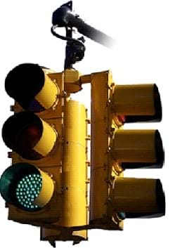
Before automobiles were invented, horses were used for transportation in big cities. Without traffic rules for pedestrians and horse carriages, streets were often overcrowded, and movement of people and goods was inefficient and dangerous. The problem was especially serious at road intersections. One solution to this congestion problem was to use police officers to control the flow of traffic, which is how it is still done in some parts of the world. Another solution, which was first used in 1868, was to install traffic lights with different colors to indicate when a vehicle should "stop," use "caution - be prepared to stop," or "go" (or, go ahead).
What colors are used in traffic lights to communicate these three messages to vehicles as well as pedestrians? (Answer: Red, yellow and green, respectively.) The reason traffic lights need to have red lights (or, "stop and wait"), is because it allows pedestrians and through traffic to pass a street intersection safely and efficiently during their own green light, which means "go ahead."
Who can come up to the board and draw a typical intersection? (Select a student to draw a traffic diagram on the classroom board.) In this intersection, how many traffic lights for vehicles are needed for safety? (Possible answers: Assuming the student drew a "cross" intersection, with one street intersecting the other, one set of traffic lights is needed for each street direction; four sets of lights, one for each direction; if "hung" in the middle of the intersection, one four-way light with a directional prong for each direction.)
The design of effective traffic light systems in modern cities is a task for traffic engineers and is an important undertaking for efficiency and safety. Traffic lights must be purposely placed to result in the safest and fastest movement of people and vehicles. Also important is the timing of traffic signals. For example, a traffic signal in a quiet suburb may safely be designed to cycle quickly between red, yellow and green, whereas a traffic signal at a busy intersection in a city business district may require longer switching times to give enough timem for vehicles and pedestrians to move safely and avoid congestion.
Until recently, traffic lights contained bulky and powerful lamps, which used a lot of electrical power, which meant they were not very energy efficient. In a city with many hundreds, or thousands, of such traffic lights, this meant the use of a lot of energy. To save energy, cities replaced lamps in traffic lights with light emitting diodes (LEDs), which use very little energy. In addition to reduction in energy use, an additional advantage of LEDs is that they have a longer service life, which means they last longer than the old-fashioned lamps. LEDs were first invented in the 1920s, and are electrical devices that can generate bright light while using very little power. Cities that switch to LEDs save a lot of energy and thus use fewer natural resources from our environment.
Procedure
Background
(Note: Many excellent online sources provide additional information about the types of traffic signs and traffic signals, street lights, duration of signal cycles, and history. If supplemental information is required, either print out information in advance or direct students to conduct pre-activity research and share their findings with the class.)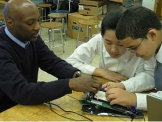
It is likely that many students are unaware of the important role traffic engineers play in their everyday lives. Thanks to traffic engineering, large metropolitan areas are able to function and conduct normal operations as safely and effectively as possible. Students get to be traffic engineers in this activity and implement a scaled-down practical model of a traffic light to learn about traffic engineering. Students take on the role of engineers (see Figure 1) tasked with building a traffic light for vehicles with a number of specifications provided by a local transportation agency. Specifications (called requirements in engineering) that must be met are: the traffic light is to have three lights (red, yellow, green), be able to shine red, yellow and green for a certain number of seconds each, and be able to repeat this sequence indefinitely.
A device called a BS2 (Basic Stamp 2) microcontroller is used to control the traffic lights. A colored LED is used for each individual light (as shown in Figure 2). As illustrated in the diagram overlaid in Figure 2, an LED is represented as a triangle with a horizontal vertical bar. Notice that an LED has one wire longer than the other. The shorter wire corresponds to the left side of the diagram (the side to the left of the vertical bar), and the longer wire corresponds to the right side. Finally, in the diagram, two arrows pointing upward from the LED represent light.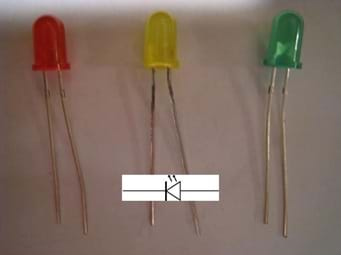
In order to use an LED, it must be connected to a power source, which is usually a battery. The correct way to connect an LED to a power source is through a device called a resistor. A resistor controls the amount of current (electrical charge) that can pass through it. A helpful analogy is to think of a resistor as a pipe, and electricity as water. A wide pipe would correspond to a small resistor value (for example 10 ohms; the smaller the number of ohms, the more electricity can pass) while a narrow pipe would correspond to a large-valued resistor. In this activity, a 470 ohm resistor is used, as depicted in Figure 3. Notice in the overlaid schematic that, in contrast to an LED, a resistor is connected without regard to direction.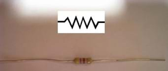
A resistor must be used together with an LED to ensure that the amount of current provided to the LED is not so great that it damages the LED. Moreover, the diode must be connected properly, with the vertical bar (that is, that shorter bar) connected to the ground terminal, "Vss." Another way to refer to "ground" is to use the minus sign (or, "-"). The circuit used to control the LED is illustrated in Figure 4.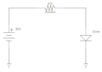
To make a traffic light in which LEDs do not have to be controlled manually, students program a BS2 microcontroller to perform the function automatically (see Figure 5). A BS2 is a small computer that can perform functions programmed by engineers. This computer is a small circuit with pins for connections. Some pins are used to provide power, while others are used to program the BS2. Still other pins are used to connect the BS2 to various devices such as resistors, LEDs, or even motors and other computers. The pin labeled P0 in the figure denotes pin 0 on the BS2.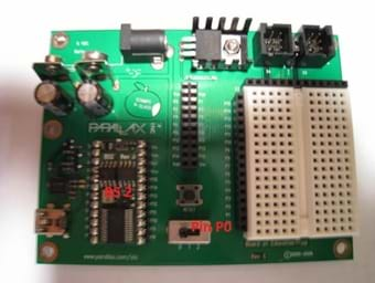
Before the Activity
- Research and copy any additional references to support class discussion.
- Set up an LED circuit using the Figure 4 diagram, as well as a working Basic Stamp traffic light, as a pre-activity demonstration.
- Install the PBASIC Stamp Editor on student computers, along with the USB drivers if using a USB version of the Board of Education.
With the Students
- Divide the class into groups of three students each, with each group having access to a computer. Assign the following roles to each team: builder, programmer and tester. The builder wires the circuit, the programmer writes the program using the PBASIC editor, and the tester runs the system and performs needed adjustments or corrections. All three team members support one another by demonstrating teamwork.
- Discuss the importance of traffic lights and street safety; support discussions with outside materials, as necessary.
- Introduce and demonstrate how to use the PBASIC editor to write, save and run PBASIC programs. Demonstrate the Board of Education, in particular the on/off switch (for this activity, set the on/off switch to position 2), and the white prototyping "breadboard" area used to build circuits. Discuss circuitry safety and precautions.
- Pass out a Board of Education to each group.
- Hand out one red LED and one 470 ohm resistor to each group, to start.
- After demonstrating a working LED, have grouops build and test a basic circuit, as illustrated in Figure 4, using the following sequence of steps.
- The programmer opens the PBASIC Stamp editor and enters the program shown in the right-hand window in Figure 6, saving the file as program1.bs2. The builder builds the circuit in Figure 4. (Refer to the help menu to learn about commands HIGH, LOW and PAUSE. Note the units in which time is measured in the PAUSE command. Also have students note that the LED in this example is connected to pin P0 on the BS2.)
- The tester runs the program and verifies the design, in consultation with others.
Sample discussion questions:
Looking at the BS2, how many input/output pins does the BS2 have? (Answer: 16 pins)
How many pins are used in this exercise? (Answer: 1 pin)
What are the units used in the PAUSE command? (Answer: Milliseconds)
What command would one have to enter to make the BS pause for 3 seconds? (Answer: PAUSE 3000)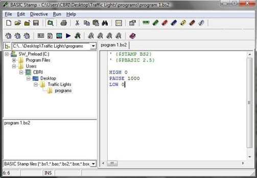
- The programmer opens a new file, and writes the program illustrated in Figure 7. All three team members look in the help menu and read about the DO LOOP statement used in this program.
Sample discussion questions:
What happens when the BS2 finishes executing the commands inside a DO LOOP? (Answer: It begins executing the commands starting at the line below the DO statement.)
For how many seconds does the LED flash in this example? (Answer: For 0.5 seconds.)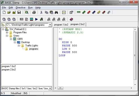
- Pass out the yellow and green LEDs along with two 470 ohm resistors. Next, each team builds a traffic light with three LEDs (red, yellow and green) with the following 45-second cycle specification:
- The red LED remains on for 10 seconds.
- The yellow LED remains on for 5 seconds.
- The green LED remains on for 30 seconds.
- The sequence repeats indefinitely.
Step 7 simulates the operation of a real-world traffic light (see Figure 8) and builds upon the program students wrote in Step 6.
Vocabulary/Definitions
Basic Stamp 2 (BS2): A type of microcontroller that can be connected to the outside world and used to come up with a solution to an engineering problem or set of specifications.
congestion: A problematic condition that occurs when movement of traffic and pedestrians has stalled due to improper function of traffic control systems and procedures, or other reasons.
conservation: Cautious and sensible use of energy and other resources that does not harm the environment.
energy: Something that can be used to perform work.
environmental impact: The effect that human activity has on the Earth, its natural processes, and all living inhabitants.
LED: Light emitting diode, an electrical device that emits light when properly connected to an electrical energy source.
microcontroller: A system that can execute user-specified commands.
resistor: An electrical component that acts to limit the amount of electrical energy flowing through it.
specifications: A set of standards that a device or system must meet in order to be an acceptable solution to a given engineering problem.
system: One or more mechanisms or devices designed to do useful work, perform a function, or solve an engineering problem.
traffic light: A system used to control the flow of vehicles and pedestrians on streets and at road intersections.
Assessment
Pre-Activity Assessment
Sharing Experiences: Lead a class discussion about student experiences with transportation and traffic safety in general. Ask students to share their own observations.
Activity Embedded Assessment
Analysis: In Steps 6 and 7, have each group try to analyze the program before loading and running it on the BS2. Instruct students to examine the DO ... LOOP statement and how it behaves. Ask students to construct practical examples of where similar functionality may be useful. Some examples of repetitive actions that can be implemented with a loop include: move the second hand on an analog clock by a given amount every one second, evenly dribble a basketball, turn pages in a book, etc.
Post-Activity Assessment
Standards: Ask students to look up traffic light standards and switching times. As an example, conduct a post-activity field trip around the school building. Using stopwatches, have students measure the traffic light patterns on a quiet residential intersection vs. a busy one. Ask students to comment on and try to explain, or "reverse engineer," the differences. Ask students to observe how each modern traffic light is composed of a number of LEDs. Challenge students to draw parallels between what they observe, the Basic Stamp program written during the exercise, and the microcontroller used. (Remind students that modern traffic lights are also controlled by microcontrollers!)
Safety Issues
- Ask students to refrain from touching the BS2 microcontroller and power circuitry on the board, as it is delicate and could break easily.
- Do not perform the activity near food or liquids.
Troubleshooting Tips
If the BS2 or the PBASIC Editor crashes, close and restart the editor, and cycle the power to the board.
Activity Extensions
Build a model of a small section of a city using LEGO® pieces, papier-mâché, or recyclable material. Use the BS2s 16 input/output lines to control approximately five 3-light traffic lights, or eight 2-light traffic lights. Have students research ways different cities control traffic, and design appropriate models for a science fair, period project, or other school event, such as the Future City competition.
Activity Scaling
- For lower grades, have students program a BS2 already outfitted with a traffic light, and provide extra assistance as needed.
- For upper grades, have students learn about the BS2 by reading the help menu provided in the PBASIC editor. Also, have students research the energy requirements of regular (incandescent) light bulbs and energy-efficient LEDs. Have students compute the percent efficiency gain of an LED vs. the light bulb. For students familiar with electric circuits, assign a research activity that involves finding the current and voltage for a regular 60 Watt light bulb and an LED. Then, have students compute the power in each case (P=IV, where I is the current and V, the voltage), and comment on the efficiency obtained in both cases.
Subscribe
Get the inside scoop on all things Teach Engineering such as new site features, curriculum updates, video releases, and more by signing up for our newsletter!More Curriculum Like This

Students are introduced to the correct technical vocabulary for lighting, which is different than layperson's terms. They learn about lamp (light bulb) technology and how to identify the various types of lighting in their spaces. They are also introduced to lighting controls as a means for saving en...
References
Basic Analog and Digital Student Guide, v1.4. Accessed October 29, 2012. http://www.parallax.com/Portals/0/Downloads/docs/books/edu/Web-BasicAnalogDigital-v1.4.pdf
StampWorks Manual, Experiments and BASIC Stamp Source Code, v2.1. Accessed October 29, 2012. (further discussion of LED-based projects, as well as other Basic Stamp activities) http://www.parallax.com/Portals/0/Downloads/docs/books/sw/Web-SW-v2.1.pdf
NYC Traffic Lights. Accessed October 29, 2012. http://www.nyc.gov/html/dot/html/faqs/faqs_signals.shtml.
Traffic Safety Marketing. The Department of Transportation Booklet. Accessed October 29, 2012. (support material) http://www.trafficsafetymarketing.gov
Traffic Light. Accessed April 20, 2009. (detailed resource about traffic lights) http://en.wikipedia.org/wiki/Traffic_light
Copyright
© 2013 by Regents of the University of Colorado; original © 2009 Polytechnic Institute of New York UniversityContributors
Pavel Khazron; Lindrick Outerbridge; Janet YowellSupporting Program
AMPS GK-12 Program, Polytechnic Institute of New York UniversityAcknowledgements
This activity was developed by the Applying Mechatronics to Promote Science (AMPS) Program funded by National Science Foundation GK-12 grant no. 0741714. However, these contents do not necessarily represent the policies of the NSF, and you should not assume endorsement by the federal government.
Last modified: February 17, 2018




User Comments & Tips