Quick Look
Grade Level: 6 (6-8)
Time Required: 30 minutes
Expendable Cost/Group: US $3.00 This activity also requires some non-expendable (reusable) items, such as an Arduino Uno microcontroller, cable, breadboard, photo sensors, resistors, wire and a BRIO wooden toy train car (~$45 for the class), plus a computer or laptop; see the Materials List for details.
Group Size: 28
Activity Dependency: None
Subject Areas: Physical Science
NGSS Performance Expectations:

| MS-PS3-1 |
| MS-PS3-5 |
Summary
Students conduct an experiment to determine the relationship between the speed of a wooden toy car at the bottom of an incline and the height at which it is released. They observe how the photogate-based speedometer instrument "clocks" the average speed of an object (the train). They gather data and create graphs plotting the measured speed against start height. After the experiment, as an optional extension activity, students design brakes to moderate the speed of the cart at the bottom of the hill to within a specified speed range.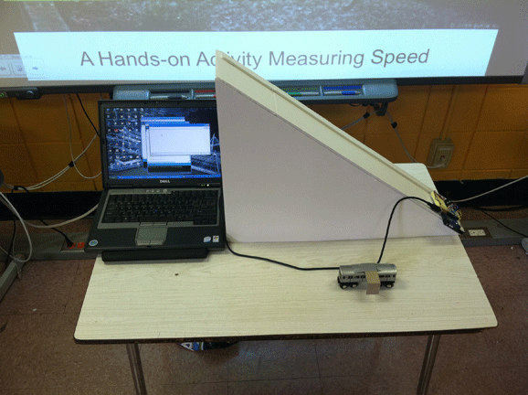
Engineering Connection
Motion of an object subject to the acceleration of gravity is a fundamental study in engineering mechanics. Engineers use the concept of potential and kinetic energy to solve real-world problems in design and analysis of dynamic systems. The student experiment is designed to inspire questions about how gravity affects the speed of objects that are free to roll or slide down inclines and develop an engineering intuition through observations of the experimental procedure and measurement data. In the design-oriented extension to design a train brake that controls the final speed to within a specified range, student designs are limited only by the material availability and speed constraint, with the goal to produce creative braking systems that result in comfortable forward car speeds.
Learning Objectives
After this activity, students should be able to:
- Describe how kinetic and potential energy is related to the speed of a rolling car on a hill.
- Describe the points of highest potential and kinetic energy given a two-dimensional path of a cart.
- Name the units used for speed measurement (meters per second).
- Predict the speed of an object that is dropped from doubling the height of drop, given the speed at the original height.
Educational Standards
Each TeachEngineering lesson or activity is correlated to one or more K-12 science,
technology, engineering or math (STEM) educational standards.
All 100,000+ K-12 STEM standards covered in TeachEngineering are collected, maintained and packaged by the Achievement Standards Network (ASN),
a project of D2L (www.achievementstandards.org).
In the ASN, standards are hierarchically structured: first by source; e.g., by state; within source by type; e.g., science or mathematics;
within type by subtype, then by grade, etc.
Each TeachEngineering lesson or activity is correlated to one or more K-12 science, technology, engineering or math (STEM) educational standards.
All 100,000+ K-12 STEM standards covered in TeachEngineering are collected, maintained and packaged by the Achievement Standards Network (ASN), a project of D2L (www.achievementstandards.org).
In the ASN, standards are hierarchically structured: first by source; e.g., by state; within source by type; e.g., science or mathematics; within type by subtype, then by grade, etc.
NGSS: Next Generation Science Standards - Science
| NGSS Performance Expectation | ||
|---|---|---|
|
MS-PS3-1. Construct and interpret graphical displays of data to describe the relationships of kinetic energy to the mass of an object and to the speed of an object. (Grades 6 - 8) Do you agree with this alignment? |
||
| Click to view other curriculum aligned to this Performance Expectation | ||
| This activity focuses on the following Three Dimensional Learning aspects of NGSS: | ||
| Science & Engineering Practices | Disciplinary Core Ideas | Crosscutting Concepts |
| Construct and interpret graphical displays of data to identify linear and nonlinear relationships. Alignment agreement: | Motion energy is properly called kinetic energy; it is proportional to the mass of the moving object and grows with the square of its speed. Alignment agreement: | Proportional relationships (e.g. speed as the ratio of distance traveled to time taken) among different types of quantities provide information about the magnitude of properties and processes. Alignment agreement: |
| NGSS Performance Expectation | ||
|---|---|---|
|
MS-PS3-5. Construct, use, and present arguments to support the claim that when the kinetic energy of an object changes, energy is transferred to or from the object. (Grades 6 - 8) Do you agree with this alignment? |
||
| Click to view other curriculum aligned to this Performance Expectation | ||
| This activity focuses on the following Three Dimensional Learning aspects of NGSS: | ||
| Science & Engineering Practices | Disciplinary Core Ideas | Crosscutting Concepts |
| Construct, use, and present oral and written arguments supported by empirical evidence and scientific reasoning to support or refute an explanation or a model for a phenomenon. Alignment agreement: Science knowledge is based upon logical and conceptual connections between evidence and explanations.Alignment agreement: | When the motion energy of an object changes, there is inevitably some other change in energy at the same time. Alignment agreement: | Energy may take different forms (e.g. energy in fields, thermal energy, energy of motion). Alignment agreement: |
Common Core State Standards - Math
-
Summarize numerical data sets in relation to their context, such as by:
(Grade
6)
More Details
Do you agree with this alignment?
-
Reporting the number of observations.
(Grade
6)
More Details
Do you agree with this alignment?
-
Describing the nature of the attribute under investigation, including how it was measured and its units of measurement.
(Grade
6)
More Details
Do you agree with this alignment?
-
Giving quantitative measures of center (median and/or mean) and variability (interquartile range and/or mean absolute deviation), as well as describing any overall pattern and any striking deviations from the overall pattern with reference to the context in which the data were gathered.
(Grade
6)
More Details
Do you agree with this alignment?
International Technology and Engineering Educators Association - Technology
-
Use instruments to gather data on the performance of everyday products.
(Grades
6 -
8)
More Details
Do you agree with this alignment?
State Standards
New York - Math
-
Describing the nature of the attribute under investigation, including how it was measured and its units of measurement.
(Grade
6)
More Details
Do you agree with this alignment?
-
Reporting the number of observations.
(Grade
6)
More Details
Do you agree with this alignment?
-
Giving quantitative measures of center (median and/or mean) and variability (interquartile range and/or mean absolute deviation), as well as describing any overall pattern and any striking deviations from the overall pattern with reference to the context in which the data were gathered.
(Grade
6)
More Details
Do you agree with this alignment?
-
Summarize numerical data sets in relation to their context, such as by:
(Grade
6)
More Details
Do you agree with this alignment?
New York - Science
-
Construct, use, and present an argument to support the claim that when work is done on or by a system, the energy of the system changes as energy is transferred to or from the system.
(Grades
6 -
8)
More Details
Do you agree with this alignment?
-
Construct and interpret graphical displays of data to describe the relationships of kinetic energy to the mass of an object and to the speed of an object.
(Grades
6 -
8)
More Details
Do you agree with this alignment?
Materials List
To share with the entire class:
- Arduino Uno microcontroller board, specifically the Arduino Uno - R3 ($30; this simple, stripped-down computer is useful for many "smart" appliance or device projects; in this activity, it receives signals from optical sensors, determines the speed of an object based on the time elapsed between sensors, and sends the latest speed data to a computer monitor; available at: 1) Radioshack, most locations carry the Uno microcontroller on the shelf, and 2) Sparkfun Electronics at https://www.sparkfun.com/, click the Products tab, scroll to the Development boards category to Arduino, and look for DEV-11021, or link directly at https://www.sparkfun.com/products/11021.)
- laptop with Arduino software installed (to install the driver on a PC or Mac, go to https://www.arduino.cc/, click on the Download tab, and follow the installation instructions for your operating system)
- USB cable, standard A-B type (the kind used with most printers)
- 1 medium-size breadboard (available at Radioshack)
- 2 photo interrupters (photo sensors) with 10 mm gap (such as the GP1A57HRJ00F, $2 each, available online at Sparkfun Electronics at https://www.sparkfun.com/products/9299)
- 2 220-ohm resistors (available at Radioshack)
- jumper wire, as needed to complete breadboard circuit (solderless breadboard jumper wire kit available at Radioshack)
- double-sided foam tape or dual-lock tape, a few strips
- 2 sheets of 18" x 24" x 3/16" thick foam core board, white or a light color
- white school glue or foam glue
- duct tape or masking tape, as needed
- BRIO wooden toy train car
- Runaway Train Pre-Activity Assessment, one per student
- Runaway Train Worksheet, one per student
- Runaway Train Post-Activity Assessment, one per student
Worksheets and Attachments
Visit [www.teachengineering.org/activities/view/nyu_train_activity1] to print or download.Pre-Req Knowledge
The ability to measure distance in centimeters. Familiarity with the concept of time and units of measurement for time.
Introduction/Motivation
If you aspire to become a successful mechanical engineer and design roller coasters or subway cars (or most other moving objects, big and small) someday, you must first learn how to analyze the motion of objects that are subjected to unbalanced forces. Gravity is a force that can cause motion of an object near the Earth's surface if that object is free to slide or roll down an incline.
Because of the constant presence of gravity acting on objects near the Earth's surface, engineers use a handy concept called potential energy. Imagine the first really high hill that a person coasts down on his or her first bicycle ride. The rider sits still at the top of the hill and stares down. If she is cautious, she might be making a mental connection between the height of the hill and how fast she will be moving at the bottom. She is aware of her potential to go fast. If she moves to a higher hill, this potential increases. At a lower hill, the potential decreases.
This idea of a potential motion is a concept engineers use to mathematically predict the speed of roller coaster cars at the bottom of hills when that potential energy is converted into kinetic energy.
Procedure
Background
Read through the entire procedure to gain familiarity with it and be able to determine the necessary level of pre-classroom activity preparation. If time permits and students are capable, include the construction of the slope assembly and the breadboard circuit as part of the overall student activity.
Before the activity, construct the ramp and speedometer. The speedometer includes a photogate. One arm of the photogate contains an infrared emitter, and the other contains an infrared detector. In the uninterrupted state, the sensor returns a high signal or 1. As soon as the beam is broken, by an obstruction preventing the otherwise uninterrupted passage of light from one gate to the other, the sensor output changes from high (1) to low (0). When the object is no longer between the uprights, the signal goes back to high (1). This can be interpreted as the sensor constantly communicating to the Arduino Uno microcontroller, telling it "true" for the uninterrupted infrared beam and "false" when the infrared beam is interrupted or blocked.
Once the set-up is ready, students take speed measurements using the speedometer. Conduct three trials for each of five different release heights. Have students record measurements in a table, graph the results, and calculate average speeds and average speed ratios for the different heights. The final part of the activity asks students to draw conclusions from this activity to determine a relationship between the speed of the wooden train at the bottom of the ramp and its release height.
Before the Activity
- Build the ramp/incline. Use the following instructions using foam core board or use your own ramp/incline. For helpful diagrams, refer to the Runaway Train Ramp Build Instructions.
- CUT the 18" x 24" foam core board diagonally from one corner to the opposite corner to result in two right triangles with 18" and 24" sides and 30" hypotenuse. This is a 3-4-5 right triangle.
- Using the second piece of 18" by 24" foam core board CUT a strip ~6" wide to make the roadway surface for the incline. To get a total length of 30," you need one 24" long strip and a second 6" long strip.
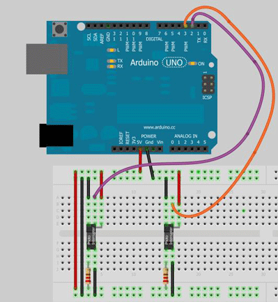
Figure 1. From the basics of electrical circuitry, robotics are pivotal to many aspects of engineering, including data collection. - Cut the inner supports for the incline: two lengths of 5-3/4" wide strips. One is 5" long and the other is 10" long. These keep the two sides from collapsing in.
- Place the two triangle sides parallel to one another and spaced ~5-3/4" apart and glue the 24" long road surface piece on top of the two triangle sides. Use duct or electrical tape to hold together the joints temporarily until the glue dries. Do the same for the second 6" long strip, to complete the 30" road surface length.
- Place the inner supports underneath so that they are approximately vertical and glue to the top surface and sides. Place the shorter piece in front at about 1/3 of the length and place the longer piece at about 2/3 of the length.
- Cut a 7/8 inch strip to provide the guide for the wooden toy train for the length of the incline, and glue in place a little off center. This does not need to be exact; place it far to the side so that the train can still have both sets of wheels touching the incline surface.
- Build the speedometer.The speedometer is made with an Arduino Uno, two photo sensors and a few other easy-to-find electronic comonents. When the Arduino is programmed with the attached script, Speedometer2sensors.ino, it measures speed using two photogate sensors, which detect any objects passing through its uprights.
- Install the first photo interrupter gate onto the breadboard, as shown in Figure 1. One side has three leads (detector) and the other has two leads (emitter). Make sure to place each lead in a separate row on the breadboard and that the gate spans the gap in the middle of the breadboard.
- Install the second photo interrupter piece onto the breadboard 12 rows down (3 cm) from the first, in the same manner that you placed the first.
- Complete the wiring between the breadboard and Arduino. You need two 220-ohm resistors, one for each of the emitter sides of each sensor; use plain jumper wires for the remainder of the connections. Refer to Figure 2.
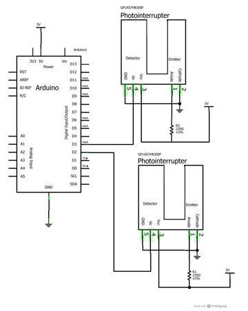
Figure 2. The engineering circuit diagram for the speedometer.
- Upload the Arduino script for the speedometer onto the Arduino Uno board.
- Make sure you have installed the driver per instructions on the arduino.cc "downloads" website. Do not proceed until this step is completed.
- Save the attached Arduino sketch file titled "Speedometer2sensors" in a folder of your choosing and remember the location where you save it.
- Open the Arduino software.
- Select Open under the File menu.
- Find and select the Speedometer2sensors sketch from the folder location where you placed it.
- The only part of the code you might need to edit is the value for the photo interrupter spacing. This line of code is highlighted by the bold green box in Figure 3. The instructions in the build call for a 3 cm center-to-center distance between the two sensors. The code, as written, will give an accurate speed for the 3 cm spacing. If the spacing is different or you want to experiment with different spacing , all that is needed is to replace the 0.03 (representing 0.03 meters) with a new value, for example, 0.05 for 5 cm, and so on.
- With the Arduino Uno board connected to the computer through a USB cord, click the upload button (the second button from the left).
- Under the Arduino menu bar, select Tools, Serial Monitor. This opens a new window that will become populated by the speed data of the most recent object passing through the photo interrupter gates.
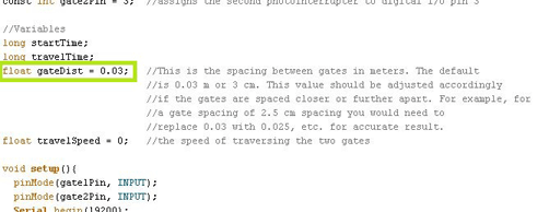
Figure 3. Students or teachers can adjust the code for different spacing between photo gates.
- Use dual lock tape to fasten the breadboard to the incline, close to the bottom.
- Cut a strip of cardboard and tape it to the BRIO train car. Using trial and error, align the cardboard to pass through the photo interrupter gates when the train moves along the roadway through the photogate.
- Make a mark on the incline surface corresponding to the midpoint of the two photo interrupters. This is the reference point. Going up the incline, make a mark every 10 cm. These points represent increments of 6 cm in height (if you made the ramp correctly the sides should follow the 3-4-5 right triangle proportions).
- Make copies of the three student handouts.
Now you are ready to conduct investigations of speed down an incline using infrared photo gates.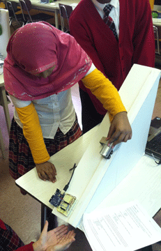
With the Students
- Start by showing the class the incline and the wooden subway car. Ask for predictions as to what will happen when the car is placed at any point of the incline and released. What is the force that is moving the car down the incline?
- Pose the central question to investigate: What happens to the speed at the bottom of the hill as I release the car at different heights? (Expect most to agree that the speed will increase.) In what way will it increase? Will the car go twice as fast when the height is doubled? What is the measurement of how "fast" an object is? What are the units?
- Introduce speed – the distance covered over an amount of time. An object traveling at a constant speed that covers 2 meters in one second is said to go 2 mps. The same object will cover 4 meters in 2 seconds, and 8 meters in 4 seconds, etc. Use this as a small game or exercise in itself to get students comfortable with the concept of speed.
- Introduce and demonstrate the sensor that is used in the experiment – infrared beams of light that when broken, send a signal to the input of a microcontroller (a small computer) signifying that an object has been detected. By positioning two of these a known distance apart, we record the travel time from one gate to the next – the result is a speed measurement, distance divided by time.
- At this point, give students time to become familiar with the device and have them practice drops. Identify roles: one student places the car, another student catches the car and reads the speed result from the laptop. Allow one or two test drops per student, and then hand out the Runaway Train Worksheet.
- The worksheet includes a table with five rows for data from five drop heights or marks, from which the car is to be released. These heights are 6 cm, 12 cm, 18 cm, 24 cm and 30 cm, which are vertical heights, not distances measured up the ramp. They correspond to the markings made when the ramp was built. The table's three columns provide three cells for each row, to accommodate data from three trials performed at each height.
- Have students write a one to two sentence hypothesis stating how they believe the speed will change as height increases. They might predict how they think the rest of the table will complete once the first row is recorded.
- To save time, all students can gather the same data to fill in their individual tables, taking turns on who drops for the 15 drops (5 heights x 3 trials) required to complete the experiment.
- Have students graph the measured speed data and write conclusions comparing the experimental result with their hypotheses.
- Discuss potential energy and kinetic energy with the students. They should understand that an object in motion possesses kinetic energy while one at rest does not. They should also understand that an object above ground level (in this case, above the bottom of the ramp) possesses potential energy, while one at ground level does not. In addition, an object with a higher speed has more kinetic energy than one at a lower speed. Likewise, an object at a higher elevation has more potential energy than one at a lower elevation.
Vocabulary/Definitions
brake: A mechanical device that inhibits movement.
gravity: A natural force that pulls two objects toward one another with a magnitude proportional to their masses. The Earth is so massive that it pulls on smaller objects on its surface with a force proportional to its mass. Weight is the result when gravity acts upon something with mass.
kinetic energy: The energy of an object that comes from its motion; kinetic energy can appear in the form of rotational motion or translating motion.
photogate: A sensor that can be used to detect the presence of an object. As an object passes through, it prevents a beam of light produced by one arm of the photogate from being detected by the other arm.
potential energy: The stored energy of an object that comes from its position with respect to a reference point (the bottom of a hill is an example of a reference point; the potential energy of a car resting on the hill is derived from the height from the bottom of the hill).
speed: The time rate of change of an object's position; distance traveled divided by the time duration of travel measured in: centimeters per second, meters per second, feet per second, miles per hour.
Assessment
Pre-Activity Assessment
Quick Quiz: To assess students' interest and prior knowledge of science, robots, gravity and speed, administer the Runaway Train Pre-Activity Assessment at the beginning of this activity.
Activity Embedded Assessment
Worksheet: During the course of the activity, have students complete the Runaway Train Worksheet to record measured data, calculate average speeds and average speed ratios, and determine a relationship between speed and train start height. Review the worksheets to gauge students' abilities to see connections and draw conclusions from the data to determine mathematical relationships.
Post-Activity Assessment
Quiz Again: At activity end, administer to students a similar quiz, the Runaway Train Post-Activity Assessment. Review their answers to see whether students' interest in or understanding of the topic changed over the course of the activity.
Troubleshooting Tips
The Arduino must be connected to a laptop to get power and the Arduino serial monitor window open to view the speeds being written to the serial terminal.
Check that the baud setting on the serial monitor is the same as the one in the code (19200).
Activity Extensions
Extend the activity by challenging students to design braking devices that, when the cart is released at a specified height, result in a speed above a minimum speed and below a maximum speed at the point of measurement. Form the class into student pairs and assign them to proceed as if they are engineering teams, following the steps of the engineering design process. (The basic steps: Understand the need, brainstorm different designs, select a design, plan-draw-diagram noting materials and tools necessary, create and test prototypes, revise to improve.) Require students to brainstorm ideas, propose several designs with sketches and bills of materials, and justify the chosen (best) design with research, citing which mechanical or other phenomena or concepts they applied to come up with their design solution. Alternatively, go through the thought process and steps of this extension activity in the form of a class discussion.
Subscribe
Get the inside scoop on all things Teach Engineering such as new site features, curriculum updates, video releases, and more by signing up for our newsletter!More Curriculum Like This

Students explore the physics exploited by engineers in designing today's roller coasters, including potential and kinetic energy, friction and gravity. During the associated activity, students design, build and analyze model roller coasters they make using foam tubing and marbles (as the cars).

High school students learn how engineers mathematically design roller coaster paths using the approach that a curved path can be approximated by a sequence of many short inclines. They apply basic calculus and the work-energy theorem for non-conservative forces to quantify the friction along a curve...

Imagining themselves arriving at the Olympics gold medal soccer game in Rio, Brazil, students begin to think about how engineering is involved in sports. After a discussion of kinetic and potential energy, an associated hands-on activity gives students an opportunity to explore energy-absorbing mate...

Students are introduced to both potential energy and kinetic energy as forms of mechanical energy. A hands-on activity demonstrates how potential energy can change into kinetic energy by swinging a pendulum, illustrating the concept of conservation of energy.
Copyright
© 2013 by Regents of the University of Colorado; original © 2012 Polytechnic Institute of New York UniversityContributors
Andrew CaveSupporting Program
AMPS GK-12 Program, Polytechnic Institute of New York UniversityAcknowledgements
This activity was developed by the Applying Mechatronics to Promote Science (AMPS) Program funded by National Science Foundation GK-12 grant no. 0741714. However, these contents do not necessarily represent the policies of the NSF, and you should not assume endorsement by the federal government.
Last modified: July 16, 2020


User Comments & Tips