Summary
Students work in pairs to create three simple types of model bridges (beam, arch, suspension). They observe quantitatively how the bridges work under load and why engineers use different types of bridges for different places. They also get an idea of the parts needed to build bridges, and their functions. The strength of model bridges is mainly a factor of the quality of materials used, and therefore they do not provide a clear visual representation of tension and compression forces involved. Yet, students are able to see these forces at work in three prototype designs and draw conclusions about their dependence on span, width and supporting structures of the bridge designs.
Engineering Connection
Many people in different branches of engineering work to build bridges. Civil engineers are responsible for design and construction of such structures, and they work with mechanical engineers and material engineers to design the most stable structures possible for given project restraints. These engineers must consider many variables when creating plans, such as distance to be spanned, where the bridge is being built (physical terrain), what type of traffic (and other loads) it must carry, materials available, budget, and what the bridge will look like.
Learning Objectives
After this activity, students should be able to:
- Create a design method.
- Observe quantitatively how bridges work under load and why engineers use different types of bridges for different places.
- Practice building techniques that civil engineers use.
Educational Standards
Each TeachEngineering lesson or activity is correlated to one or more K-12 science,
technology, engineering or math (STEM) educational standards.
All 100,000+ K-12 STEM standards covered in TeachEngineering are collected, maintained and packaged by the Achievement Standards Network (ASN),
a project of D2L (www.achievementstandards.org).
In the ASN, standards are hierarchically structured: first by source; e.g., by state; within source by type; e.g., science or mathematics;
within type by subtype, then by grade, etc.
Each TeachEngineering lesson or activity is correlated to one or more K-12 science, technology, engineering or math (STEM) educational standards.
All 100,000+ K-12 STEM standards covered in TeachEngineering are collected, maintained and packaged by the Achievement Standards Network (ASN), a project of D2L (www.achievementstandards.org).
In the ASN, standards are hierarchically structured: first by source; e.g., by state; within source by type; e.g., science or mathematics; within type by subtype, then by grade, etc.
NGSS: Next Generation Science Standards - Science
| NGSS Performance Expectation | ||
|---|---|---|
|
MS-ETS1-2. Evaluate competing design solutions using a systematic process to determine how well they meet the criteria and constraints of the problem. (Grades 6 - 8) Do you agree with this alignment? |
||
| Click to view other curriculum aligned to this Performance Expectation | ||
| This activity focuses on the following Three Dimensional Learning aspects of NGSS: | ||
| Science & Engineering Practices | Disciplinary Core Ideas | Crosscutting Concepts |
| Evaluate competing design solutions based on jointly developed and agreed-upon design criteria. Alignment agreement: | There are systematic processes for evaluating solutions with respect to how well they meet the criteria and constraints of a problem. Alignment agreement: | |
| NGSS Performance Expectation | ||
|---|---|---|
|
MS-ETS1-3. Analyze data from tests to determine similarities and differences among several design solutions to identify the best characteristics of each that can be combined into a new solution to better meet the criteria for success. (Grades 6 - 8) Do you agree with this alignment? |
||
| Click to view other curriculum aligned to this Performance Expectation | ||
| This activity focuses on the following Three Dimensional Learning aspects of NGSS: | ||
| Science & Engineering Practices | Disciplinary Core Ideas | Crosscutting Concepts |
| Analyze and interpret data to determine similarities and differences in findings. Alignment agreement: | There are systematic processes for evaluating solutions with respect to how well they meet the criteria and constraints of a problem. Alignment agreement: Sometimes parts of different solutions can be combined to create a solution that is better than any of its predecessors.Alignment agreement: Although one design may not perform the best across all tests, identifying the characteristics of the design that performed the best in each test can provide useful information for the redesign process—that is, some of the characteristics may be incorporated into the new design.Alignment agreement: | |
International Technology and Engineering Educators Association - Technology
-
Requirements for design are made up of criteria and constraints.
(Grades
6 -
8)
More Details
Do you agree with this alignment?
-
Brainstorming is a group problem-solving design process in which each person in the group presents his or her ideas in an open forum.
(Grades
6 -
8)
More Details
Do you agree with this alignment?
-
Make two-dimensional and three-dimensional representations of the designed solution.
(Grades
6 -
8)
More Details
Do you agree with this alignment?
-
The selection of designs for structures is based on factors such as building laws and codes, style, convenience, cost, climate, and function.
(Grades
6 -
8)
More Details
Do you agree with this alignment?
-
Structures rest on a foundation.
(Grades
6 -
8)
More Details
Do you agree with this alignment?
-
Buildings generally contain a variety of subsystems.
(Grades
6 -
8)
More Details
Do you agree with this alignment?
-
Develop innovative products and systems that solve problems and extend capabilities based on individual or collective needs and wants.
(Grades
6 -
8)
More Details
Do you agree with this alignment?
-
Analyze how an invention or innovation was influenced by its historical context.
(Grades
6 -
8)
More Details
Do you agree with this alignment?
-
Refine design solutions to address criteria and constraints.
(Grades
6 -
8)
More Details
Do you agree with this alignment?
-
Create solutions to problems by identifying and applying human factors in design.
(Grades
6 -
8)
More Details
Do you agree with this alignment?
-
Critue whether existing and proposed technologies use resources sustainably.
(Grades
9 -
12)
More Details
Do you agree with this alignment?
State Standards
Massachusetts - Science
-
Describe and explain parts of a structure, e.g., foundation, flooring, decking, wall, roofing systems.
(Grades
6 -
8)
More Details
Do you agree with this alignment?
-
Identify and describe three major types of bridges (e.g., arch, beam, and suspension) and their appropriate uses (e.g., site, span, resources, and load).
(Grades
6 -
8)
More Details
Do you agree with this alignment?
-
Explain how the forces of tension, compression, torsion, bending, and shear affect the performance of bridges.
(Grades
6 -
8)
More Details
Do you agree with this alignment?
-
Describe and explain the effects of loads and structural shapes on bridges.
(Grades
6 -
8)
More Details
Do you agree with this alignment?
Materials List
- cork tiles cut into 12 x 4-in (30.5 x 10.2 cm) pieces
- thick foamies (2 mm-thick sheets of foam material)
- ruler (12-in)
- permanent marker or a pen that can write on cork and foam
- wooden skewers or florist sticks (with wire removed)
- string
- toothpicks
- tape
- large embroidery needle (to thread string through cork)
Worksheets and Attachments
Visit [www.teachengineering.org/activities/view/wpi_bridge_joy_act] to print or download.Introduction/Motivation
When engineers are building a new road they try to pick a route with the fewest number of huge obstacles. Sometimes such a path is impossible to find, especially if a long river, large lake, or deep valley is in the region. When this problem occurs, civil engineers must find a way to safely cross the obstacle according to specifications provided by the town or state. Sometimes the best solution is a tunnel. Sometimes the best solution is a bridge.
In today's activity, you will be acting as engineers and be given scenarios that require you to come up with the best bridge design for each.
(Depending on the level of students, provide students with specific bridge designs for each scenario, or direct students to begin without any plan, as a more open-ended challenge.)
Your engineering team has three missions to complete. You will design and present these prototype bridge designs in order to "sell" your plans to the clients.
Scenario 1: A High School Campus
A school in Minnesota needs a foot bridge to provide its students, teachers and visitors a faster, more comfortable way across a small stream on campus. Winters in Minnesota are extremely cold, and summers can be quite warm. Therefore, the bridge must be able to withstand extreme weather temperatures, as well as the many feet of snow and wind gusts from winter blizzards. The school would like the new bridge to blend into the community, but also be short so as to reduce cost. As the designers of this bridge, you must satisfy each of these requirements so you may be rehired to build another bridge in the future.
- low cost
- handicapped accessible
- simple design
- ability to withstand extreme weather conditions
- aesthetically pleasing (looks nice)
Scenario 2: Building in Boston
Today city planners design towns and cities so that traffic patterns are smooth, and buildings are easily accessible from these roadways. As one of the first cities in the U.S, Boston, MA, was not planned in this way. The first settlers in this area did not have much reason to travel across the city, and therefore Boston was not designed with large roadways or long bridges. Now the city is growing and needs a bridge twice as long as the current one. The new bridge must accommodate heavy traffic, including individual and public transportation systems. The people of this historic city would like the new bridge to become an elegant landmark.
- very stable
- support large amounts of traffic
- elegant design
- low cost for most safety
Scenario 3: Art Museum Design
An art museum in New Mexico has hired you to build a bridge that resembles a Roman Aqueduct for their permanent exhibit on Ancient Rome. The museum board of trustees wants to ensure that the new bridge is as safe as possible; however they want the bridge to stand out as a wonderful artistic addition to their historic display.
- strong
- stone
- aesthetically pleasing
- historically accurate
Procedure
General Procedure
As the engineering team hired to build these three bridges, you and your group must first decide what type of bridge is appropriate for each of the three scenarios. You should develop a prototype of the bridge you plan on building, based on Table 1.
Be sure to include (and label!) the following parts in your drawing:
- length
- span
- parts carrying horizontal weight
- parts carrying vertical weight
Measure and cut out the pieces for each bridge design.
1. Beam Bridge
a) Measure out a 3.5 x 2-in (8.9 x 5 cm) piece of cork. This represents a road, and will be referred to as "road" through the rest of the instructions.
b) Measure a ¼-in (0.6-cm) square in each of the four corners of your road, and place a dot on the inside corner. Connect the dots to form a ¼-in (0.6-cm) border on all four sides of the rectangle (see Figure 1).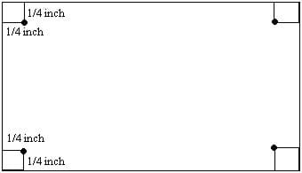
c) Take four toothpicks, and draw a line ½-in (1.3-cm) from the top on each toothpick (see Figure 2).
d) Push each toothpick into each of the four corners of your road where you placed the dots in step b.
e) Push the toothpicks through so that the top of the road is covering the mark you made in step c, as shown in Figure 3.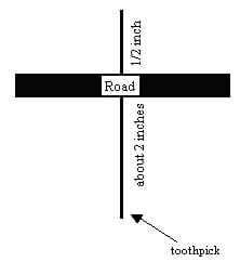
f) Now that you have a freestanding bridge supported in four corners, push the other end of each toothpick into the foam you are using as the ground (see Figure 4). 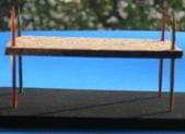
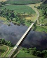
2. Arch Bridge
a) The arch bridge requires another piece of cork to add support. Measure out two pieces of 6 x 2-in (15.2 x 5-cm) cork.
b) Label one piece ROAD. This represents the road, and will be referred to as "road" through the rest of the instructions.
c) Measure a ¼-in (0.6-cm) square in each of the four corners of the road, and place a dot on the inside corner. Connect the dots to form a ¼-in (0.6-cm) border on all four sides of the rectangle, as you did for the beam bridge (see Figure 1).
d) Take four toothpicks, and draw a line ½-in (1.3-cm) from the top on each, once again, as you did for the beam bridge (see Figure 2).
e) Push each toothpick into each of the four corners of your road where you placed the dots in step c.
f) Push the toothpicks through so that the top of the road is covering the mark you made in step c, as shown in Figure 3.
g) Now that you have a freestanding bridge supported in four corners, push the other end of each toothpick into the foam you are using as the ground (see Figure 4).
h) Ending with this step would provide you with a beam bridge, however your goal is an arch bridge. So, insert a second 6 x 2-in (15.2 x 5-cm) cork piece between the four toothpicks and under your road to support it (see Figure 6).
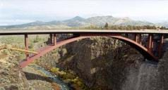
i) Push the road surface down so that it is supported by the newly formed arch. You will have to imagine that the road continues down to this ground on either side of your bridge, as you can see in Figure 7.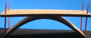
3. Suspension Bridge
a) Measure out a 12 x 2-in (30.5 x 5-cm) piece of cork. This represents the road, and will be referred to as "road" through the rest of the instructioins.
b) Measure a ¼-in (0.6-cm) square in each of the four corners of your road, and place a dot on the inside corner. Connect the dots to form a ¼-in (0.6-cm) border on all four sides of the rectangle as you did on the beam and arch bridges (see Figure 1).
c) Take four toothpicks, and draw a line ½-in (1.3-cm) from the top on each (see Figure 2).
d) Push each toothpick into each of the four corners of your road where you placed the dots in step b.
e) Push the toothpicks through so that the top of the road is touching the mark you made in step c, as shown in Figure 3.
f) Now that you have a freestanding bridge supported in four corners, push the other end of each toothpick into the "ground." You will have to imagine that the road continues down to the ground on either side of your bridge, as can be seen in Figure 5.
g) Gently press in the middle and notice how much weaker this longer structure is.
h) To strengthen the bridge (and make it a suspension bridge), cut four 6-in (15.2-cm) "towers" from your skewers.
i) Measure 2 in (5 cm) from the bottom of each skewer and make a mark, as you did for the toothpicks in step b (see Figure 8).
j) Also measure and place a dot 3 in (7.6 cm) from each end of the cork road.
k) Push the wooden skewers through these dots so that the road is covering the marks you made on them in step i.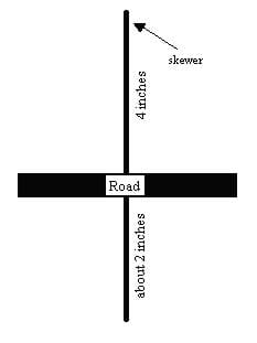
l) Cut two pieces of string long enough to use as cables across your bridge (you can start with more then you need and cut away the excess later; see Figures 11 and 12).
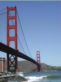
m) Insert the string halfway between the two skewers along the 12-in (30-cm) side and pull it through the other side. Repeat this process on the opposite 12-in (30-cm) side. Tie the string around the stick and then around the toothpick, pulling tight. On a real bridge, these cables would look like those in Figure 11.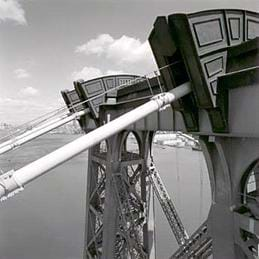
n) Your completed bridge should end up looking like the real bridge in Figure 11, or like the one shown in Figure 12.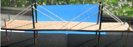
Vocabulary/Definitions
compression: The act of squeezing or pressing together.
prototype: A model of something to be further developed.
tension: The force on a body that produces strain.
torsion: Strain produced by twisting.
Assessment
Rubric: Use the attached Teacher Rubric to evaluate student performance and accomplishment in the bridge activity, including criteria on construction, understanding of the topic, and teamwork.
Investigating Questions
- List the pros and cons of each bridge used in each of the three scenarios (Fill in the attached Chart 1).
- How do changes in length affect tension, compression, torsion, and bending, as the width remains constant?
- Put some light pressure on each of bridge type and evaluate the tension, compression, torsion, and bending.
- Which bridge type would have the most problems - such as torsion or bending - if you did not build it carefully?
- List different examples for the use of each bridge. Which would be most useful for crossing a river? For crossing a channel? Connecting two islands together? Building a highway or a railroad? Creating aqueducts?
- Bonus question: Why do soldiers stop marching in cadence (rhythm) when they cross a bridge?
Subscribe
Get the inside scoop on all things Teach Engineering such as new site features, curriculum updates, video releases, and more by signing up for our newsletter!References
What's a Bridge? Chippewa Valley Museum, WI. Accessed December 19, 2011. (Covers beam, truss, suspension and arch bridges with photo examples) http://www.cvmuseum.com/Museum2/home.htm
Copyright
© 2013 by Regents of the University of Colorado; original © 2005 Worcester Polytechnic InstituteContributors
Joy Trahan-LiptakSupporting Program
K-12 Outreach Office, Worcester Polytechnic InstituteAcknowledgements
Creation of this activity was funded by Pratt & Whitney.
Last modified: August 21, 2018



User Comments & Tips