Quick Look
Grade Level: 9 (9-12)
Time Required: 45 minutes
Expendable Cost/Group: US $15.00 Note: This activity uses a non-expendable (reusable) LEGO MINDSTORMS robot kit, color sensors and software for each group; see the Materials List for details.
Group Size: 4
Activity Dependency: None
Subject Areas: Physical Science

Summary
Students learn about rotary encoders and discover how they operate through hands-on experimentation. Rotary encoders are applied in tools to determine angle measurements and for translations of angular motion. One common rotary encoder application is in a computer's ball-type mouse—the ball itself is a type of rotary encoder. In this activity, students experiment with two rotary encoders, including one from a computer mouse and one created using a LEGO® MINDSTORMS® EV3 kit. They collect data to define and graph the relationship between the motion of the rotary encoder and its output.Engineering Connection
Engineers must understand existing designs in order to select and integrate the most cutting-edge and efficient technologies available to create state-of-the-art machinery, devices, processes and systems. Rotary encoders are a useful technology to measure rotational motion with a relatively simple mechanism. Although simple in design, rotary encoders have been incorporated in a wide range of applications designed by engineers, particularly mechanical and electrical. Specifically, encoders are used to control height in elevators, speeds in escalators, motorized wheelchairs and wind turbines. Also, they are used to determine angular direction in computer mice, and set a target angle in industrial robotic arms. They are a necessary and useful component to many technological creations that improve our lives.
Learning Objectives
After this activity, students should be able to:
- Define rotary encoder and explain how one works.
- Measure and graph the relationship between the angular motion of a rotary encoder and its output based on a linear translation.
- List examples of how rotary encoders are used in devices and mechanisms.
Educational Standards
Each TeachEngineering lesson or activity is correlated to one or more K-12 science,
technology, engineering or math (STEM) educational standards.
All 100,000+ K-12 STEM standards covered in TeachEngineering are collected, maintained and packaged by the Achievement Standards Network (ASN),
a project of D2L (www.achievementstandards.org).
In the ASN, standards are hierarchically structured: first by source; e.g., by state; within source by type; e.g., science or mathematics;
within type by subtype, then by grade, etc.
Each TeachEngineering lesson or activity is correlated to one or more K-12 science, technology, engineering or math (STEM) educational standards.
All 100,000+ K-12 STEM standards covered in TeachEngineering are collected, maintained and packaged by the Achievement Standards Network (ASN), a project of D2L (www.achievementstandards.org).
In the ASN, standards are hierarchically structured: first by source; e.g., by state; within source by type; e.g., science or mathematics; within type by subtype, then by grade, etc.
Common Core State Standards - Math
-
Understand and apply theorems about circles
(Grades
9 -
12)
More Details
Do you agree with this alignment?
-
Visualize relationships between two-dimensional and three-dimensional objects
(Grades
9 -
12)
More Details
Do you agree with this alignment?
-
Solve linear equations and inequalities in one variable, including equations with coefficients represented by letters.
(Grades
9 -
12)
More Details
Do you agree with this alignment?
-
Represent data on two quantitative variables on a scatter plot, and describe how the variables are related.
(Grades
9 -
12)
More Details
Do you agree with this alignment?
International Technology and Engineering Educators Association - Technology
-
A prototype is a working model used to test a design concept by making actual observations and necessary adjustments.
(Grades
9 -
12)
More Details
Do you agree with this alignment?
-
Illustrate principles, elements, and factors of design.
(Grades
9 -
12)
More Details
Do you agree with this alignment?
Materials List
Each group needs:
- 1 computer ball mouse
Note: Computer ball mice can be purchased online at Amazon, Ebay, lessEMF or other resellers for ~$10 each; ball mice, not optical mice, must be used. The mouse should have a USB connection; adapters can be purchased online at Tiger Direct. Tracking mice, with a ball mechanism (not an optical mechanism), will suffice.
- screwdriver
- duct tape
- laptop with an on-screen pixel ruler and drawing program
- ruler
- paper
- calculator
- 1 wide-tipped marker
- Rotary Encoders Pre-Activity Worksheet, one per student
- Encoder Worksheet, one per student
- Results and Analysis Worksheet, one per student
For the LEGO MINDSTORMS EV3 rotary encoder demonstration setup: (Note: In advance of the activity, prepare one LEGO MINDSTORMS EV3 rotary encoder for each group.)
- LEGO MINDSTORMS EV3 robot, such as EV3 Core Set (5003400) at https://education.lego.com/en-us/products/lego-mindstorms-education-ev3-core-set/5003400#lego-mindstorms-education-ev3
- LEGO MINDSTORMS color sensor (in addition to the one provided in the Core Set), available at https://shop.lego.com/en-US/EV3-Color-Sensor-45506
- masking tape
- scissors
- box cutter
- 2-3 sheets of white copy/drawing paper
- manila folder
- Rotary Encoder Building Instructions
- 1 printed copy of Rotary Encoder Cutout
- Rotary Encoder Display Program
Note: This activity can also be conducted with the older (and no longer sold) LEGO MINDSTORMS NXT set instead of EV3; see below for those supplies:
- LEGO MINDSTORMS NXT robot, such as the NXT Base Set
- LEGO MINDSTORMS Light Sensor (in addition to the one provided in the Base Set)
- Rotary Encoder Building NXT Instructions
Worksheets and Attachments
Visit [www.teachengineering.org/activities/view/nyu_encoders_activity1] to print or download.Pre-Req Knowledge
Students should know the definition of an angle, as well as be comfortable measuring angles in degrees. As necessary, teach students how to measure angles with a protractor and provide time to practice this skill before starting the activity. They should also be comfortable graphing data and converting values from one unit to another.
Introduction/Motivation
In today's world, people interact with computers and electronic devices in many of their daily activities. In almost all of these devices, people's physical actions are transmitted through mechanical devices that are interpreted by computers or electrical circuits (see Figure 1). Actions are transmitted through mechanisms via buttons, dials, knobs and punch cards. Then the interpreted information is displayed on the device or fed back to the user so their interactions with the computer can be understood. 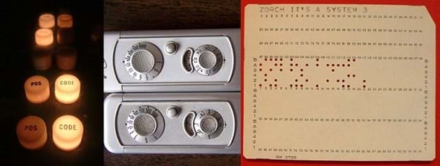
Today, we focus on rotary encoders. A rotary encoder is an electro-mechanical device that converts angular position to a linear translation. This might sound complicated, but you are more familiar with the work of rotary encoders than you realize. In the 1990s, transmitting information from a person's actions into a personal computer using a computer mouse became a common use of rotary encoders. The computer mouse can be used to accomplish a great deal of work on the computer by working in a two-dimensional virtual space. Surprisingly, the mechanism of a computer ball mouse, the type of computer mouse with a rolling ball in the base, is simple, having only two rotary encoders. One rotary encoder is for the up-and-down movements on the computer screen and the second is for left-and-right movements. 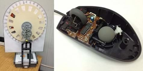
Procedure
Background
In this activity, a LEGO MINDSTORMS robotic mechanism is used to demonstrate the principles of the rotary encoder using two color sensors. The turning motion of the rotary wheel is translated into a command that changes a counter displayed on the computer. Students measure and record target angles and corresponding computer angles for this setup. As necessary, provide students with a quick review of how to measure angles with a protractor.
Then students use computer mice to explore and quantify the relationship between the motion of the computer mouse and the motion of the mouse cursor visible on the monitor.
Through disassembly of the mouse, students see how moving the rotary encoder affects the mouse cursor on the laptop screen. After reassembly of the mouse, students compare the changes in the computer mouse movement and the mouse cursor movement. Students repeat this experiment for up to 10 lengths of motion, graphing their observations of the computer mouse movement and the mouse cursor movement between trials. To test the mouse/cursor movement relationship, students attach a marker to the mouse to draw on paper while using a drawing program to "draw" the mouse on screen.
To conclude the activity, hold a class discussion on the applications of rotary encoders, and other human-computer interactions. For example, rotary encoders are applied in elevators to calibrate the elevator motors to the height of the building floors, and in wind turbines to measure the speed of the rotating blades and report values to the system controls.
Before the Activity
- Build a LEGO MINDSTORMS demonstration rotary encoder for each group following the Rotary Encoder Building Instructions and using the Encoder Cutout. Download the Rotary Encoder Display Program (rotaryencoderdisplay.c) on each LEGO MINDSTORMS EV3 brick. Detailed instructions on how to complete this download are provided on the building instructions.
- Disassemble and reassemble a computer ball mouse to practice identifying the rotary encoder. For help finding the rotary encoders, refer to Figure 4.
- Perform the full activity by following the steps in the With the Students section to develop the relationship between the movement of the computer mouse and the motion of the mouse cursor.
- Gather materials and make copies of the Encoder Worksheet and Results and Analysis Worksheet, one each per student.
With the Students
Class Demonstration
- Introduce the concept of rotary encoders and ask each student group to refer to their LEGO MINDSTORMS rotary encoder.
- Explain to students that by using two encoders, the position of the wheel on the demonstration encoder can be accurately determined.
- Help students turn on the Rotary Encoder Display Program (rotaryencoderdisplay.c) on the LEGO EV3. Go to: LEGO EV3 > My Files > Software Files>rotaryencoderdisplay > Run.
- The program automatically increases in +6 degrees increments; slightly turn the wheel so that the angle increases by +6 degrees for a counterclockwise turn. Direct students to turn the wheel to observe how the program changes the displayed angle, as the wheel turns. Refer to Figure 3 to see how the angle on the rotary encoder wheel (left) and the corresponding "angles" on the LEGO MINDSTORMS brick (right) are displayed, differently, in this case, because of the +6 degrees of change.
- Explain that the +6 degrees of change comes from the resolution of the device. In engineering, measurements can only give a very close approximation of a physical quantity; some measurement error will always exist. For example, engineers can measure distance in several ways, including the use of a ruler. However to get a more accurate measurement, many engineers and scientists use a caliper or laser.
- Explain to students that if they choose a number such as 31, the display might show only 30 or 36 because those numbers are multiples of 6 (again, refer to Figure 3).
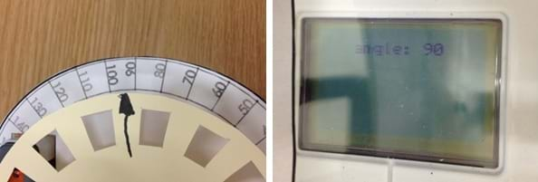
Figure 3. LEGO EV3 rotary encoder angle measurement.
Class Demonstration: Prediction
- Ask students to select an angle at random to be the target on the demonstration encoder, which is the large wheel component made from the paper and the manila folder; have them record this predicted value as the "Predicted Angle" on their Encoder Worksheets.
- Have students turn the encoder (the wheel) to the predicted angle and notice that the MINDSTORMS EV3 Brick displays the computer angle.
Class Demonstration: Data Collection
- Students read and record the "Computer Angle" value displayed on the Brick on their worksheets. (Note: Students later comment on their findings on the Results and Analysis Worksheets.)
Class Demonstration: Discussion
- Students calculate the percent error value following the instructions in the activity sheet. Ask students for their percent error value. Explain that having minimal error is best for engineering designs. For example, if a rotary encoder has a value of 1% for the percent error, and if it was used in an elevator to move people to the 100th floor, it would deliver people to the 99th floor.
Discovery Phase
- Have students disassemble the computer ball mouse to identify the rotary encoder inside.
- Instruct students to sketch on their worksheets diagrams of the computer ball mouse. Draw in the rotary encoder and label it in the diagram. (Note: Refer to Figure 4 for assistance in identifying the rotary encoders.)
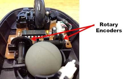
Figure 4. The rotary encoders in a computer ball mouse.
Data Collection Phase
- Have students reassemble the computer ball mouse.
- Direct students to turn on their laptops and plug the computer ball mouse into a USB port. Open a web browser and go to: https://www.rapidtables.com/web/tools/pixel-ruler.html, which provides an onscreen pixel ruler.
- Have students place their worksheet with the six-inch drawn line on top of their mouse pads (or alternatively, use the sheet of paper as their mouse pad). Align the cord of the mouse with the 0 on the line drawn on the worksheet, and move the cursor to point at the 0 position on the onscreen pixel ruler.
- Tell students to move their mouse from 0 to 1 inch, and observe the change in the cursor placement on screen. Have them record the distance their mouse moved on screen (in pixels) on their worksheets. (Note: At this point, advise students not to assume they know what is going to happen; the results are surprising.)
- Instruct students to repeat step #4 of this section for all lengths 1, 2, 3, 4, and 5 inches, and graph the collected data in the space provided on their worksheets.
Qualitative Data Collection Phase
- Direct students to use duct tape to attach a marker to their mouses in such a way that the mouse/marker draws on a paper below the mouse when moved (see Figure 5).
- Have students open a drawing program (such as Windows Paint® or GIMP) on their laptops and set the computer mouse, with the attached marker, on a blank sheet of paper. Using their mouse, instruct one student to draw as they normally would, while the marker simultaneously draws on the paper. Have students take turns drawing something on their laptops. Have students reflect on the results on their Results and Analysis Worksheets.
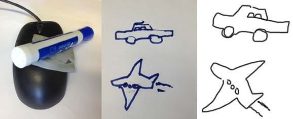
Figure 5. Conversion of hand motions into the computer.
Vocabulary/Definitions
angular position: A point or location that can be described by an angle.
electro-mechanical device: A device that combines electrical and mechanical processes to operate.
linear translation: Constant movement along a single direction; movement along a straight line.
mouse cursor: A pointer visible on the computer monitor that indicates a position.
pixel: The smallest element in a display device or monitor.
pixel-to-length ratio: The amount of pixels measured for a given physical length traveled by the computer mouse.
rotary encoder : An electro-mechanical device that converts the angular motion of an axle to an analog or digital code.
Assessment
Pre-Activity Assessment
Pre-Activity Worksheet: To assess students' prior knowledge of rotary encoders and angle measurements, have them complete the Rotary Encoders Pre-Activity Worksheet.
Question/Answer: To get students to begin thinking about the function of rotary encoders, ask them the following questions:
- What factors might determine how people interact with computers. (Possible answers: Efficiency of an interface to help people perform tasks, ease of use of computer software, and reliability of the hardware device.)
- How would elevators know the exact location to open doors, or how does a computer mouse know where to position the cursor. (Answer: Rotary encoder.)
Activity Embedded Assessment
Activity Worksheet: While students work on the activity, move around the room and observe their progress on the Encoder Worksheet. Ask students what factors might change the pixel-to-length ratio, meaning the amount of pixels in a given length that the mouse moves during the activity. (Example answers: Paper or table surface roughness, computer screen size, computer mouse translation code, speed of the measurement, and steadiness of the human hand.)
Post-Activity Assessment
Results and Analysis Worksheet: To assess students' understanding of rotary encoders, how they function and how they are used, as well as angle measurements, have them complete the Results and Analysis Worksheet. This worksheet also asks students to report their findings from their experiments by explaining the relationships between the motion of the rotary encoders and the corresponding output.
Investigating Questions
Would the rotary encoder work for any other shapes, such as a square? (Answer: No, a square would cause some problems, such as uneven slits, weak encasing cover due to shape, or might not even register on the encoder depending on the slit location.)
How do you think rotary encoders are applied in elevators and fans? (Answer: An elevator regulates the distance of the elevator box as the motor turns. A fan can regulate the speed of the blades with an encoder.)
Activity Extensions
Conduct the Ding! Going Up? Elevators and Engineering activity.
Subscribe
Get the inside scoop on all things Teach Engineering such as new site features, curriculum updates, video releases, and more by signing up for our newsletter!Copyright
© 2013 by Regents of the University of Colorado; original © 2013 Polytechnic Institute of New York UniversityContributors
Paul Phamduy; Chris Leung; Janet YowellSupporting Program
AMPS GK-12 Program, Polytechnic Institute of New York UniversityAcknowledgements
This activity was developed by the Applying Mechatronics to Promote Science (AMPS) Program funded by National Science Foundation GK-12 grant no. 0741714. However, these contents do not necessarily represent the policies of the NSF, and you should not assume endorsement by the federal government.
Last modified: July 21, 2023


User Comments & Tips