
Quick Look
Grade Level: 6 (5-7)
Time Required: 45 minutes
Expendable Cost/Group: US $0.00 This activity uses LEGO parts and software; see the Materials List for details.
Group Size: 3
Activity Dependency: None
Subject Areas: Measurement, Physical Science, Science and Technology
NGSS Performance Expectations:

| MS-PS4-2 |
Quick Look
- Grade Level:
- 6 (5 – 7)
- Time Required:
- 45 minutes
- Group Size:
- 3
- Subject Areas:
-
Measurement Physical Science Science and Technology -
NGSS Performance Expectations:
MS-PS4-2

Summary
Students learn about ultrasound and how it can be used to determine the shapes and contours of unseen objects. Using a one-dimensional ultrasound imaging device (either prepared by the teacher or put together by the students) that incorporates a LEGO® MINDSTORMS® EV3 intelligent brick and ultrasonic sensor, they measure and plot the shape of an unknown object covered by a box. Looking at the plotted data, they make inferences about the shape of the object and guess what it is. Students also learn how engineers use high-frequency waves in the design of medical imaging devices, the analysis of materials and oceanographic exploration. Pre/post quizzes, a worksheet and a LEGO rbt program are provided.Engineering Connection
Scientific diagnosis depends on the acquisition of data. Imaging-based diagnosis is one example of a tool used to gather information for decision making. For this purpose, engineers have developed several devices, including x-rays and sonograms, which are commonly used in medicine; infrared thermo-graphic cameras and video surveillance cameras used in the military; and sonar, which is commonly used to detect underwater objects or defects and fatigue in machinery components. Among these devices, sonogram and sonar both rely on the use of ultrasound-based imagery to map the shapes of objects. Compared to x-rays, ultrasound is less harmful to the human body and thus widely used for diagnosis-based imaging in hospitals, industries and remote exploration.
Learning Objectives
After this activity, students should be able to:
- Write a simple program for the LEGO EV3 intelligent brick.
- Gather and record data using an ultrasonic sensor.
- Scale data and make a plot on graph paper.
- Analyze the plot obtained to make inferences about the geometry of the hidden object.
- Infer the shape of the hidden object based on the one-dimensional projection of its shape.
- Determine the relationship between the grid size and the resolution of the ultrasound image.
Educational Standards
Each Teach Engineering lesson or activity is correlated to one or more K-12 science,
technology, engineering or math (STEM) educational standards.
All 100,000+ K-12 STEM standards covered in Teach Engineering are collected, maintained and packaged by the Achievement Standards Network (ASN),
a project of D2L (www.achievementstandards.org).
In the ASN, standards are hierarchically structured: first by source; e.g., by state; within source by type; e.g., science or mathematics;
within type by subtype, then by grade, etc.
Each Teach Engineering lesson or activity is correlated to one or more K-12 science, technology, engineering or math (STEM) educational standards.
All 100,000+ K-12 STEM standards covered in Teach Engineering are collected, maintained and packaged by the Achievement Standards Network (ASN), a project of D2L (www.achievementstandards.org).
In the ASN, standards are hierarchically structured: first by source; e.g., by state; within source by type; e.g., science or mathematics; within type by subtype, then by grade, etc.
NGSS: Next Generation Science Standards - Science
| NGSS Performance Expectation | ||
|---|---|---|
|
MS-PS4-2. Develop and use a model to describe that waves are reflected, absorbed, or transmitted through various materials. (Grades 6 - 8) Do you agree with this alignment? |
||
| Click to view other curriculum aligned to this Performance Expectation | ||
| This activity focuses on the following Three Dimensional Learning aspects of NGSS: | ||
| Science & Engineering Practices | Disciplinary Core Ideas | Crosscutting Concepts |
| Develop and use a model to describe phenomena. Alignment agreement: | A sound wave needs a medium through which it is transmitted. Alignment agreement: When light shines on an object, it is reflected, absorbed, or transmitted through the object, depending on the object's material and the frequency (color) of the light.Alignment agreement: The path that light travels can be traced as straight lines, except at surfaces between different transparent materials (e.g., air and water, air and glass) where the light path bends.Alignment agreement: A wave model of light is useful for explaining brightness, color, and the frequency-dependent bending of light at a surface between media.Alignment agreement: However, because light can travel through space, it cannot be a matter wave, like sound or water waves.Alignment agreement: | Structures can be designed to serve particular functions by taking into account properties of different materials, and how materials can be shaped and used. Alignment agreement: |
Common Core State Standards - Math
-
Model with mathematics.
(Grades
K -
12)
More Details
Do you agree with this alignment?
-
Represent real world and mathematical problems by graphing points in the first quadrant of the coordinate plane, and interpret coordinate values of points in the context of the situation.
(Grade
5)
More Details
Do you agree with this alignment?
-
Represent and interpret data.
(Grade
5)
More Details
Do you agree with this alignment?
-
Graph points on the coordinate plane to solve real-world and mathematical problems.
(Grade
5)
More Details
Do you agree with this alignment?
-
Reporting the number of observations.
(Grade
6)
More Details
Do you agree with this alignment?
International Technology and Engineering Educators Association - Technology
-
Students will develop an understanding of the relationships among technologies and the connections between technology and other fields of study.
(Grades
K -
12)
More Details
Do you agree with this alignment?
-
Advances and innovations in medical technologies are used to improve healthcare.
(Grades
6 -
8)
More Details
Do you agree with this alignment?
State Standards
New York - Math
-
Represent real world and mathematical problems by graphing points in the first quadrant of the coordinate plane, and interpret coordinate values of points in the context of the situation.
(Grade
5)
More Details
Do you agree with this alignment?
-
Graph points on the coordinate plane to solve real-world and mathematical problems.
(Grade
5)
More Details
Do you agree with this alignment?
-
Represent and interpret data.
(Grade
5)
More Details
Do you agree with this alignment?
-
Reporting the number of observations.
(Grade
6)
More Details
Do you agree with this alignment?
New York - Science
-
Develop and use a model to describe that waves are reflected, absorbed, or transmitted through various materials.
(Grades
6 -
8)
More Details
Do you agree with this alignment?
Materials List
Each group needs:
- graph paper
- ruler
- pencils
- Ultrasound Imaging Worksheet
To share with the entire class:
- small cardboard box
- box cutter (for use by the teacher)
- LEGO MINDSTORMS EV3 robot, such as EV3 Core Set (5003400) at https://education.lego.com/en-us/products/lego-mindstorms-education-ev3-core-set/5003400#lego-mindstorms-education-ev3
- LEGO MINDSTORMS Education EV3 Software 1.2.1, free online, you have to register a LEGO account first. At https://www.lego.com/en-us/mindstorms/downloads/download-software
- computer, loaded with EV3 1.2.1 software
- LEGO ultrasonic sensor (included in LEGO core set, above); at https://shop.lego.com/en-US/EV3-Ultrasonic-Sensor-45504
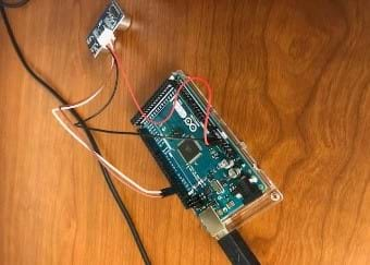
- LEGO parts to build a sensor mount; one method: attach sensor using four long LEGO pins and make a cursor/pointer from 1 long LEGO pin, which are items included in the base set (see Figure 1)
- USB cable (included in LEGO base set)
- ruler and marker, to measure and draw a grid on the top of the box corridor (see Figure 1a); to avoid any confusion, number the grid as shown in the photograph; also, choose two grid sizes, such as ½ inch and 1 or 2 inches.
- an assortment of objects from which one (or more) will be hidden in the box, choose objects with simple yet distinguishable shapes, such as a ball, cube, soda can, coffee cup or bowl, that are not too small and that fit in the box
Alternative: LEGO MINDSTORMS NXT Set:
Note: This activity can also be conducted with the older (and no longer sold) LEGO MINDSTORMS NXT set instead of EV3; see below for those supplies:
- LEGO MINDSTORMS NXT robot, such as the LEGO MINDSTORMS NXT Base Set and NXT 2.1 software
- computer loaded with the NXT 2.1 software
 A photograph shows a palm-sized device that has two round openings. (right) A drawing shows three shapes: red pyramid, yellow sphere, blue cube.")
Worksheets and Attachments
Visit [www.teachengineering.org/activities/view/nyu_ultrasound] to print or download.Pre-Req Knowledge
Students must be familiar with coordinate systems, measurements units (cm, inches) and conversion between units, and plotting using graph paper. They should also be familiar with basic geometric shapes such as triangles, rectangles, circles, cylinders, spheres and cubes.
Introduction/Motivation
Sounds are common in our environment and result from mechanical vibrations that propagate through a medium, typically air. For human beings and other animals, sound is used to transmit information. Sound waves are classified by their frequencies. For example, audible sound waves used in our daily communication include all frequencies between 20 Hz and 20000 Hz. The hertz unit describes the number of cycles per second of a given wave. Sounds emitted over the range of frequency of 20,000 Hz are inaudible to people and are called "ultrasound." Sounds below the audible frequency of 20 Hz are called "infrasound." from a sender/receiver traveling a distance, r, to an object, and returning curved lines (reflected wave) returning from the object to the sender/receiver.")
The properties of these inaudible sounds are used in engineering to transmit data and explore unseen surfaces. Among the technologies using these properties of sound, ultrasound imaging has found wide use in a range of applications. One application of this technology in medicine is the sonograph, which is used to view internal body organs and check on the development of fetuses. In industry, ultrasound imaging is used to detect defects or any signs of fatigue in materials or machine parts. For example, as part of routine maintenance, the wings of aircraft undergo regular ultrasound imaging to determine if they need any repair or parts replacement. This helps to keep us safe when flying aboard commercial jets. In oceanography, sonars are used to detect the presence of everything from schools of fish to underwater coral or unusual objects as well as to map the terrain of the deep and unseen ocean floor. The technology of sonar helps to locate missing boats and sunken planes in deep water before launching rescue operations.
Now consider that you are an ultrasound imaging engineer, and your responsibility is to look into deep water to find a missing object. This might be some long lost treasure or a sunken ship or airplane. Using your eyes is not enough to find these objects, but an ultrasound imaging device can be built to explore deep water terrain by emitting ultrasound waves from a ship down into the deep water. If any unusual objects are detected, the emitted ultrasonic waves bounce against the obstacle, redirecting the waves up, where they are detected by a receiver and analyzed to figure out the shape and type of object detected.
Ultrasound imaging is based on a simple physical principle, that is, the motion of any wave is affected by the medium through which it travels. So, if you send a wave inside water and it encounters an obstacle, such as a rock, the wave bounces against the obstacle and the wave characteristics change. By comparing the properties of the new waves received back to the initial wave emitted, a visual picture of the object can be obtained.
In our experimental setup in the classroom, if no obstacle exists, the waves bounce against the surface of the table and we read a constant value. If an object blocks the waves from reaching the table, the waves bounce against the object and return back, giving us a different reading. Assuming all other factors such as temperature and pressure are constant, sound travels at a constant speed of 331.4 meters per second in air. By measuring the wave's roundtrip time, we can determine the distance between the object and the ultrasonic sensor. By recording the measurements from specific grid points, and then plotting the distance measured on graph paper, we can obtain the shape of the object being detected.
Thanks to advancements in engineering, today this process is entirely done for us by computer programs. In this activity, we only require basic tools to help us read experimental data obtained from an ultrasonic sensor. By plotting the data on graph paper, we have what we need to make a scientific guess of the shape of the hidden object.
The branches of engineering that are related to this activity include mechanical and computer engineering. Mechanical engineers design sensors that are able to produce and detect ultrasound waves. Computer programmers design the programs that read, analyze and display the sensor data on the screen, such as the LEGO intelligent brick we are using today. Like engineers, we also use our math skills to scale and convert the data so it can be plotted on a Cartesian coordinate system.
Procedure
Before the Activity
Gather materials and make copies of the Ultrasound Imaging Worksheet.
Construct the ultrasound imaging experimental setup, which includes a cardboard box, LEGO ultrasonic sensor, EV3 intelligent brick, and a grid drawn on the top of the box, by following the steps below. If more LEGO EV3 parts are available, make several experimental setups and/or have student groups construct their own setups.
- Use a box cutter to cut a corridor (a long, narrow slit) in the middle of one side of the box of about the length of the box. Ideally, set the length of the corridor to ~30 cm (~11.8 inches) to accommodate large objects.
- Draw the grid on the top of the corridor using a ruler, as shown in Figure 1a. To avoid any confusion, number the grid as shown in the photograph. Also, choose two grid sizes, such as ½ inch and 1 or 2 inches.
- Use LEGO parts to build a sensor mount, such as shown in Figure 1c and 1d.
- Mount the EV3 brick on one side of the box by making four holes in the box and affix it using four long LEGO pins (see Figure 1b).
- Mount the ultrasonic sensor so that it can easily slide along the corridor. Make sure the sensor is connected to the appropriate EV3 brick port. To position the sensor as shown in Figure 1a, create a cursor (pointer) from a long LEGO pin.
- Make sure the EV3 brick battery is charged.

Figure 1. a) An external view of the device with a half-inch grid and the cursor/pointer on top; b) the interior of the box with the ultrasonic sensor mounted using a long LEGO pin to the cursor; c) and d) how the cursor and sensor are connected to their mounting mechanisms.
Prepare the computer with the Ultrasound Distance Program (an rbt file). Upload the program into the EV3 brick. If the classroom is equipped with enough computers, prepare one per group.
In advance of the activity, you may want to determine the distance from the sensor to the table under the box with no object in the box; this maximum distance is what students need to know to make calculations. Otherwise, do this during the activity while being careful not to disclose to students the identity of the hidden object.
With the Students
- Introduce the activity using the Introduction/Motivation section, which discusses the topics of the science of ultrasound, engineering applications and ultrasound imaging.
- Introduce the basic experimental setup.
- Divide the class into groups and hand out worksheets and graph paper to each group. Tell students that the goal of the exercise is to use the experimental setup to guess the object hidden inside the box.
- Go over the Ultrasound Distance Program (the rbt file) with students. Explain the role of each component of the program as described in the text guide of the program. If groups have computer access, have students reproduce the code in the order the components appear. Upload the program into the EV3 brick.
- Ideally, ask students to perform the experiment initially with a large grid size (1 or 2 inches), then with a smaller grid size (1/2 inch), and ask them to compare and contrast what they observe and why. Note that a smaller grid size (1/2 inch) gives a better object shape than a larger grid size (1 or 2 inches).
- To operate the ultrasound imaging device, have students first select the ultrasound_distance.rbt program or select the ultrasound program available on the LEGO EV3 brick program, by selecting the view option and navigating with the gray button to find the ultrasonic display measurement program. When using the built-in LEGO EV3 program, either inches or centimeters may be chosen for the ultrasonic display measurement program; choose the one your students are most comfortable with (or choose one and have them convert to the other unit). The Ultrasound Distance Program is in inches and can accommodate centimeters by changing the scale factor in the scale converter block by 2.54.
- Show the class several objects with different shapes that can fit inside the box, such as a small ball, small cube, bar, soda can, coffee cup, etc. Since the experimental setup is basic, the object shape must also be simple.
- In the absence of an object inside the box, the EV3 brick displays the distance from the sensor to the table underneath the box. This measurement is the maximum distance to the table (if the box sits on top of a table). Determine (and record on the classroom board) this distance before inserting any object inside the box. Press the EV3 brick red button twice to display on its screen the distance.
- Without letting students see, choose one of the objects and place it at the bottom of the experimental setup box. Make sure that the object is lined up with the corridor on the top of the box. Hide the other objects out of sight so students do not guess the hidden object's identity by its absence.
- Direct students to position the sensor cursor at a grid location and then press the orange button twice on the EV3 brick to display on the screen the distance from the sensor to the object. Direct them to record this measurement on their worksheets.
- When recording data with an object inside the box, students must first compute the object's height, which is the difference between the distance of the sensor to the table (maximum distance recorded) and the distance recorded from the sensor to the object.
- Students then use grid paper to plot this difference data on an x-y axis. Note: on the x-axis, students plot the grid points, and on the y-axis, students plot the object height computed for each grid point. At the end, they use straight lines to join the plotted points. Require students to label both the x and y axes and give the graph a title. (See Figure 2 for an example x-y plot.)

Figure 2. Example x-y plot of a mystery object's height. - In their groups, have students discuss their results and observations. In particular, direct students to discuss the effect of grid size on the plot.
- Bring the class together and ask students to guess the shape of the hidden object and give their opinions on which grid size gives a better picture of the object.
- Based on the objects presented to the class prior to the experiment, ask them to predict which object likely has that shape and is the hidden object.
- Continuing the class discussion, based on the experiment conducted, ask students to explain how ultrasound imaging works and to describe in their own words how it works to enable us to visualize a fetus or explore the deep surface of the ocean in search of missing objects.
Vocabulary/Definitions
Cartesian coordinate system: A coordinate system comprised of two axes, the x-axis and y-axis, which are perpendicular to each other and have a common origin. A Cartesian coordinate defines the position of a point relative to these two axes.
coordinate: An ordered pair of numbers that uniquely identifies a position in a space.
emitter: The part of a sensor that generates a signal.
frequency: A measure of how often something occurs per unit of time.
grid: A network of horizontal and perpendicular lines, uniformly spaced, that results in regularly spaced points at the line intersections.
hertz: The standard unit of frequency. Abbreviated as Hz. 1 Hz equals one cycle per second.
receiver: The part of a sensor that detects a signal.
sensor: A mechanical device that converts physical measurements into electrical signals.
sonar: A distance measurement instrument that sends out an ultrasound pulse and measures the time for the echo to return.
ultrasound: A sound wave with a frequency between 20,000 Hz and 2 million Hz, which is above human audible sound frequencies.
ultrasound imaging: Use of the reflections of high-frequency sound waves to create images.
Assessment
Pre-Activity Assessment
Pre-Activity Quiz: Assign students to complete the three-question Ultrasound Imaging Pre-Activity Quiz before class. Collect and review students' answers to gauge their baseline understanding of x-rays, sonar and ultrasound and help you to guide the discussion and explanations during the activity.
Informal Discussion: Ask students some questions about the subject matter, covering the questions and the Ultrasound Imaging Pre-Activity Quiz Answers. Ask students:
- What is sonar? Where have you seen sonar used? (Answer: Sonar is a distance measurement instrument that sends an ultrasound pulse and measures the time for the echo to return. Sonar is commonly used for ocean navigation, fishing and deep sea exploration.)
- Have you ever heard of ultrasound? (Students may have not heard of ultrasound, but if they have, encourage them to explain how/where [media, family member, etc.] they have heard about it and what it is.)
- Apart from the x-ray machine, does any other method exist that takes pictures of organs inside our bodies? (Answer: Yes, the sonograph is an example.)
Activity Embedded Assessment
Analysis: While the experiments are being conducted, have students complete the Ultrasound Imaging Worksheet by recording and plotting data, and observing and drawing the pattern. Review students' worksheet answers, plots and inferences to gauge their depth of comprehension.
Post-Activity Assessment
Discussion: Ask students to comment on how they could use ultrasound imaging technology to explore deep underwater terrain, a canyon, a volcano or some other non-accessible locations to find missing items or discover unknown territory. Administer the four-question Ultrasound Imaging Post-Activity Quiz. If problem 4 is too challenging, work through it as a class.
Safety Issues
- To reduce the likelihood of any injuries, permit only the teacher to use the box cutter.
Troubleshooting Tips
Make sure the equipment is set up correctly, the battery is charged, and the ultrasonic sensor is connected to the appropriate LEGO brick port.
Make sure the object inside the box is aligned with the corridor.
Refer to the operating instructions for the LEGO MINDSTORMS EV3 provided with the base set. Refer to the LEGO EV3 website for any other issues: https://www.lego.com/en-us/mindstorms/support/.
The precision of the EV3 ultrasonic sensor is about ±1 cm. Hence, measurements taken on identical objects might differ in that range. For example, the plot of data recorded from a ball might not look smooth. Also, note that the measurements do not include decimal points.
Activity Extensions
Expand the grid to navigate in two dimensions in order to obtain a 3D object shape.
Add unit conversion practice to this activity by having students record measurements in centimeters and then convert them into inches.
Activity Scaling
For lower grades:
- Provide more in-depth explanations of ultrasound, speed, distance and imaging.
- Work through the activity slowly, with more explanations throughout. Focus more on vocabulary and concept review before starting the activity.
For upper grades:
- Have student groups build their own, individual experimental setups.
- Let students decide which unit to use (centimeters or inches) and an appropriate grid size.
- Have students record and plot their data using Microsoft Excel®.
- To adapt this activity for high school students, modify the experimental setup to record the data in two dimensions, so that in addition to moving the sensor along a straight line, also move it in a perpendicular direction.
Subscribe
Get the inside scoop on all things Teach Engineering such as new site features, curriculum updates, video releases, and more by signing up for our newsletter!More Curriculum Like This

Students learn vocabulary necessary for understanding how ultrasonic waves are reflected and refracted. Students also see how ultrasound technology is used in medical devices.
Students learn about sound waves and use them to measure distances between objects. They use ultrasound waves to measure distances and understand how ultrasonic sensors are engineered.

Students learn about echolocation: what it is and how engineers use it to "see" things in the dark, or deep underwater. They also learn how animals use echolocation to catch their meals and travel the ocean waters and skies without running into things.

Students learn about how ultrasonic sensors work, reinforcing the connection between this sensor and how humans, bats and dolphins estimate distance. They learn the echolocation process—sound waves transmitted, bounced back and received, with the time difference used to calculate the distance of obj...

References
Fenster, Aaron, and Donal B. Downey. "3-D Ultrasound Imaging: A Review." Engineering in Medicine and Biology Magazine, IEEE. 15.6 (1996): pp. 41-51.
Kompis, Martin, Hans Pasterkamp, and George R. Wodicka. "Acoustic Imaging of the Human Chest." Chest Journal. 120.4 (2001): pp. 1309-1321.
Simmons, James A., and Roger A. Stein. "Acoustic Imaging in Bat Sonar: Echolocation Signals and the Evolution of Echolocation." Journal of Comparative Physiology. 135.1 (1980): pp. 61-84.
Sutton, Jerry L. "Underwater Acoustic Imaging." Proceedings of the IEEE. 67.4 (1979): pp. 554-566.
Copyright
© 2014 by Regents of the University of Colorado; original © 2013 Polytechnic Institute of New York UniversityContributors
Violet MwaffoSupporting Program
AMPS GK-12 Program, Polytechnic Institute of New York UniversityAcknowledgements
This activity was developed by the Applying Mechatronics to Promote Science (AMPS) Program funded by National Science Foundation GK-12 grant no. 0741714. However, these contents do not necessarily represent the policies of the NSF, and you should not assume endorsement by the federal government.
Last modified: October 25, 2020
User Comments & Tips