Quick Look
Grade Level: 7 (6-8)
Time Required: 3 hours
(can be split into different days; more time can be used for advanced sections)
Expendable Cost/Group: US $0.00 This activity uses non-expendable (reusable) teacher-prepared PFPD kits, ~$600 each; see the Materials List for details.
Group Size: 3
Activity Dependency:
Subject Areas: Science and Technology
NGSS Performance Expectations:

| MS-PS2-2 |

Summary
Working in teams, students learn the basics of fluid power design using the PFPD as their investigative platform. They investigate the similarities and differences between using pneumatic and hydraulic power in the PFPD. With the main components of the PFPD already assembled, student groups determine the correct way to connect the valves to the actuators using colored, plastic tubing. Once connected, they compete in timed challenges to test their abilities to separate material out of containers using the PFPDs. NOTE: No special pre-requisite knowledge is required for students to be successful in this activity.Engineering Connection
Over the years, engineers have applied the many benefits of fluid power to a wide variety of everyday purposes (as discussed in the associated lesson). Many people are familiar with the pneumatics found under office chairs and the hydraulics in heavy machinery at construction sites. In what other ways can fluid power be used to benefit people in our society? Engineers are currently designing and testing the use of fluid power to create powerful and lightweight rescue robots and innovative hydraulic hybrid vehicles.
Learning Objectives
After this activity, students should be able to:
- Identify devices that utilize fluid power.
- Identify and explain basic components and functions of fluid power devices.
- Differentiate between the characteristics of pneumatic and hydraulic systems.
- Create and test a hydraulic and/or pneumatic device using a provided kit.
Educational Standards
Each TeachEngineering lesson or activity is correlated to one or more K-12 science,
technology, engineering or math (STEM) educational standards.
All 100,000+ K-12 STEM standards covered in TeachEngineering are collected, maintained and packaged by the Achievement Standards Network (ASN),
a project of D2L (www.achievementstandards.org).
In the ASN, standards are hierarchically structured: first by source; e.g., by state; within source by type; e.g., science or mathematics;
within type by subtype, then by grade, etc.
Each TeachEngineering lesson or activity is correlated to one or more K-12 science, technology, engineering or math (STEM) educational standards.
All 100,000+ K-12 STEM standards covered in TeachEngineering are collected, maintained and packaged by the Achievement Standards Network (ASN), a project of D2L (www.achievementstandards.org).
In the ASN, standards are hierarchically structured: first by source; e.g., by state; within source by type; e.g., science or mathematics; within type by subtype, then by grade, etc.
NGSS: Next Generation Science Standards - Science
| NGSS Performance Expectation | ||
|---|---|---|
|
MS-PS2-2. Plan an investigation to provide evidence that the change in an object's motion depends on the sum of the forces on the object and the mass of the object. (Grades 6 - 8) Do you agree with this alignment? |
||
| Click to view other curriculum aligned to this Performance Expectation | ||
| This activity focuses on the following Three Dimensional Learning aspects of NGSS: | ||
| Science & Engineering Practices | Disciplinary Core Ideas | Crosscutting Concepts |
| Plan an investigation individually and collaboratively, and in the design: identify independent and dependent variables and controls, what tools are needed to do the gathering, how measurements will be recorded, and how many data are needed to support a claim. Alignment agreement: Science knowledge is based upon logical and conceptual connections between evidence and explanations.Alignment agreement: | The motion of an object is determined by the sum of the forces acting on it; if the total force on the object is not zero, its motion will change. The greater the mass of the object, the greater the force needed to achieve the same change in motion. For any given object, a larger force causes a larger change in motion. Alignment agreement: All positions of objects and the directions of forces and motions must be described in an arbitrarily chosen reference frame and arbitrarily chosen units of size. In order to share information with other people, these choices must also be shared.Alignment agreement: | Explanations of stability and change in natural or designed systems can be constructed by examining the changes over time and forces at different scales. Alignment agreement: |
International Technology and Engineering Educators Association - Technology
-
Students will develop an understanding of the relationships among technologies and the connections between technology and other fields of study.
(Grades
K -
12)
More Details
Do you agree with this alignment?
-
Transportation vehicles are made up of subsystems, such as structural propulsion, suspension, guidance, control, and support, that must function together for a system to work effectively.
(Grades
6 -
8)
More Details
Do you agree with this alignment?
-
Power is the rate at which energy is converted from one form to another or transferred from one place to another, or the rate at which work is done.
(Grades
6 -
8)
More Details
Do you agree with this alignment?
State Standards
Indiana - Science
-
Explain that power is the rate that energy is converted from one form to another.
(Grade
7)
More Details
Do you agree with this alignment?
Materials List
Each group needs:
- 1 PFPD kit (teacher-prepared*)
- laminated handouts of PFPD schematic and fluid power basics
- 2 containers, one filled with mixed "material," one empty; example material: white and colored Styrofoam pieces
*The PFPD kits are not available for sale. They were designed using common parts that can be ordered or found locally and can be put together by teachers or their support organizations. See the PFPD Assembly Manual for a parts list, bill of materials, assembly instructions and safety instructions. The bill of materials includes suggested sources and part numbers. Some teachers have used local grants to secure the funding to purchase parts and then engaged higher ability students to build the kits for use in other classes. For additional questions, refer to the associated lesson and the following CCEFP websites: http://www.ccefp.org/education/teaching-and-learning-resources/, http://www.ccefp.org/get-involved/k-12-teachers/teaching-and-learning-resources and http://ccefp.org/-13.
To share with the entire class:
- access to source of compressed air
- towels and/or mops to clean up any spilled water
Worksheets and Attachments
Visit [www.teachengineering.org/activities/view/pur_fluidpower_act] to print or download.Introduction/Motivation
(Note: During the following question and answer section, make sure every student is involved by either speaking at least once or by assisting the teacher with the demonstration.)
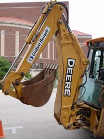
By a show of hands, how many of you have seen a larger version of this (teacher pointing towards the PFPD) before? Now how many of you know what it is called? (Answer: An excavator.) Where have you seen them being used? (Answer: At construction sites for new roads, buildings, etc.) Why do you think we use them? (Answer: They make heavy jobs easier, faster and more safe.) The back of a backhoe is very similar to the arm you will find on an excavator (see Figure 2).
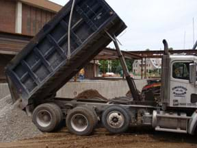
Before we had these machines, did people do these same jobs of lifting heavy objects and moving dirt? (Answer: Yes) How did we do it? (Answer: We used human and animal power, longer hours to do the jobs, unsafe working conditions, etc.) What makes these machines so powerful? (Answer: Fluid power – specifically, hydraulics in heavy machinery.) See Figure 3.
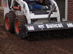
Besides allowing one to utilize very powerful forces, fluid power can also provide the user with precision control along with those forces. A skid steer can be outfitted with a variety of attachments that at times require precise control. Whether it is backfilling dirt up against a building or tilling up the soil (see Figure 4), the hydraulic power in this fluid power system enables a skid steer operator to control the machine with the precision needed to not damage the building. Again the question remains, "what did people do to complete this job before fluid power was invented?" (Answer: Used a garden tiller and many more hours to complete the job. OR used a shovel or spade and worked with their hands.)
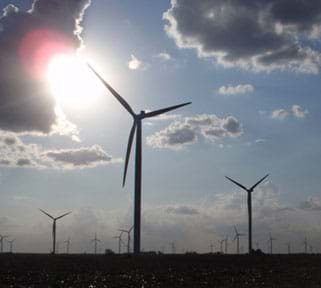
Fluid power, which is a relatively old technology, is being utilized in a variety of new applications. One application is the modern wind turbine generators being built around the country (see Figure 5). These 300-foot tall wind turbines are designed to convert wind energy into electricity. To maximize the turbine efficiency, the blades and the base of the blades must rotate slightly to catch the wind at specific angles. Hydraulic power is often used to rotate the pitch mechanisms of these 60-120-foot long blades. Would we have as many wind turbines today without the use of fluid power? (Answer: Probably not.) Is there another technology that could be used to do the same job? (Answer: Yes, electric motors.) Would it be as efficient? (Answer: Probably not.)
Procedure
Before the Activity
- Divide the class into groups of two or three students per PFPD. If not enough PFPDs for the entire class, have the remaining students work on the associated Fluid Power Basics lesson and rotate students through both as time permits.
- Make sure all plastic hoses that connect the valves to the actuators are detached completely from the PFPD (see Figure 6) and lying off to the side of the demonstrator.
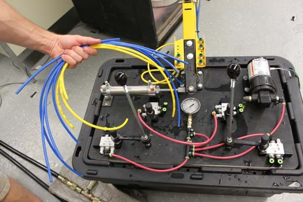
Figure 6. Make sure to detach all the hoses that connect the valves to the cylinders. This should include all the blue and yellow colored hoses. - For the first teacher demonstration, make sure the PFPD is running on pneumatic power.
- For when students do the activity, have PFPDs filled with water in the bottom of the container (reservoir) to make them hydraulic devices.
- SAFETY NOTE: Before allowing student to run PFPD with compressed air (pneumatics), adjust the valves accordingly so arm and linkages do not move too quickly and risk causing injury to someone.
With the Students
- Discuss the basics of fluid power with students. Using the source of compressed air, regulate the air pressure to about 30 psi if possible. On the PFPD, unplug the source air hose to demonstrate how much (or little) 30 psi really is. See Figure 7. Use the example that many passenger car tires are inflated to 35 psi. Place your thumb or finger over the hose so students can hear how it changes the air flow escaping from the hose end. Plug the air hose back into PFPD.
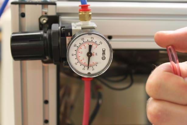
Figure 7. Place a thumb over a hose that is releasing air at 30 psi; listen and feel how much pressure it is. How much work can air at this pressure really do? - Detach one of the smaller actuators from the PFPD, but keep the hoses connected to both the value and actuator being demonstrated. Operate the connected valve to move the actuator to the extended position. Place a 10-lb free weight (or comparable weight you may have) on the end of the actuator and place a threaded nut and washer to keep the weight from slipping off. Hold the cylinder for the actuator up in the air so all students can see the 10-lb weight attached to the bottom of actuator. See Figure 8.
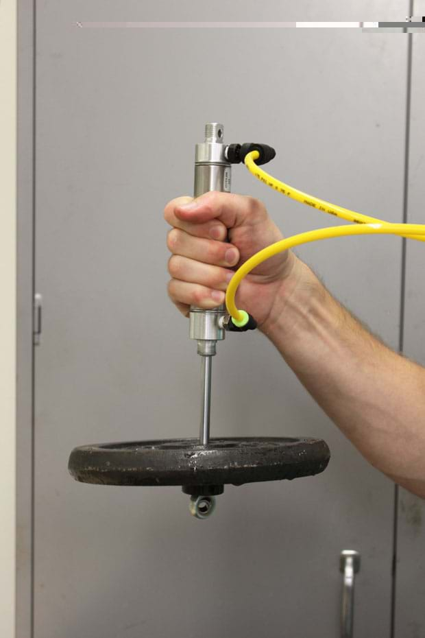
Figure 8. As the valve is activated to allow 30 psi into the cylinder, notice how easily the 10 lb weight is pulled up. - While holding up the actuator, ask students "How many of you think this small actuator, using compressed air at 30 psi, will be able to lift this 10-lb weight EASiLY?" How many of you think it will not be able to do it? How many don't really know? (Have one of the actuators detached from the PFPD, but keep the hoses attached. Place the 10-lb free weight on the end. While holding the actuator and weight in the air, use the valve to control the lifting and lowering of the weight.)
- Discuss how easily the pneumatic powered actuator lifted the weight. Ask students to think of other examples that they have seen or used in their own daily lives in which pneumatics or hydraulics are used for jobs requiring high forces.
- Make sure all PFPDs are running as hydraulic systems using the water and pump, which is not plugged in at this time (no pressure!).
- Before assigning students to the PFPDs, detach all red and blue connection hoses that run from the valves to the actuators (see Figure 6). Place the hoses beside the PFPD from which they came.
- Divide the class into groups of two or three students each, depending on the size of the class and the number of PFPDs available. If not enough PFPDs, rotate the students through the task cards while others are working on the PFPDs.
- Have students connect the appropriate valves to the associated actuators. Have students refer to the handout to determine which valves and actuators are to be connected.
- Once students think they have connected all the hoses correctly, have them plug in pump to pressurize the system. While referring to their handouts, have them operate all the valves on the PFPD to determine if they match the handout.
- Once the PDPD is determined to be connected correctly, have students practice operating it to get familiar and skilled with how to precisely control the excavator arm. Make sure each student gets an opportunity to operate the PFPD at some point during this exercise.
- Challenge students to see how quickly they can move certain pieces of material from one large container to the other. (Note: If too difficult to move certain pieces, have students move all pieces from one container to another.) See Figure 9.
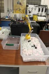
Figure 9. Have students connected the hoses correctly? Does it operate as it states in the handout? How did they go about problem solving if it wasn't connected properly?
Vocabulary/Definitions
absolute pressure: The total pressure exerted on a system, including atmospheric pressure.
atmospheric pressure: The pressure exerted by the weight of the atmosphere above the point of measurement.
Boyle's law: The volume of a gas at constant temperature varies inversely with the pressure exerted on it.
Charles' law: The volume of a confined gas is proportional to its temperature, provided its pressure remains constant.
check valve: A valve that allows flow in one direction but prevents flow in the opposite direction.
compressor: An air pump that compresses air into a receiver tank.
crank: A part of an axle or shaft bent out at right angles, for converting reciprocal to circular motion and vice versa.
cylinder: A device used to convert fluid power into mechanical power in the form of linear motion.
directional-control valve: Used to control which path fluid takes in a circuit.
double-acting cylinder: A cylinder that can act under pressure in both directions (extend and retract) to move a load.
filter: A device used to remove contamination from a fluid.
flow meter: A device used to measure flow rate.
flow rate: The volume of fluid that moves through a system in a given period of time.
flow velocity: The distance the fluid travels through a system in a given period of time.
flow-control valve: Used to start and stop flow in a circuit.
fluid power: The use of a fluid (liquid or gas) to transmit power from one location to another.
Gay-Lussac's law: The absolute pressure of a confined gas is proportional to its temperature, provided its volume stays constant.
hydraulics: The use of a liquid flowing under pressure to transmit power from one location to another.
lubricator: A device used to spray an oil mist into the stream of a pneumatic system.
Pascal's law: Pressure exerted by a confined fluid acts undiminished equally in all directions.
piston: A sliding piece moved by or moving against fluid pressure which usually consists of a short cylindrical body fitting within a cylindrical chamber or vessel along which it moves back and forth.
pneumatics: The use of gas flowing under pressure to transmit power from one location to another.
pressure: The force per unit area exerted by a fluid against a surface.
pressure regulator: A type of pneumatic pressure control valve that controls the maximum pressure in a branch of a circuit.
pressure relief valve: A type of pressure control valve that limits the maximum pressure in a hydraulic or pneumatic circuit.
pump: A device used to create flow in a hydraulic system.
receiver tank: A device that holds the compressed air in a pneumatic system.
reservoir: The tank that holds the fluid in a hydraulic system.
single-acting cylinder: A cylinder that acts under pressure in one direction only and returns automatically when the pressure is released.
solenoid: A switching device that uses the magnetic field generated by an electrical current for actuation.
transmission lines: Used to transport fluid in a circuit.
valve: Any device that controls, either automatically or manually, the flow of a fluid.
viscosity: A measure of a fluid's thickness or resistance to flow.
volume: The amount or quantity of something.
Assessment
Pre-Activity Assessment
Voting & Demo: Ask students to vote by a show of hands their opinions to the following question. Tally the votes and write the numbers on the board.
- How many of you think this small actuator, using compressed air at 5 psi, will be able to lift this 5-lb weight? How many of you think it will not be able to do it? How many don't really know? (Have one of the actuators detached from the PFPD, but keep the hoses attached. Place a 5-lb barbell weight on the end. While holding the actuator and weight in the air, use the valve to control the lifting and lowering of the weight.)
Activity Embedded Assessment
Prediction: Before using PFPD, ask students to guess how long it will take to move one piece of colored Styrofoam (or other material) from one bin to another. Record estimated times on the board.
Problem Solving: Have students prepare short write-ups that describe in detail how they went about problem solving trying to get the PFPD connected to operate as the schematic specified. Require that they provide detail on what contributions they provided to group progress, one thing their groups did well, and one thing their groups could have done better.
Fluid Power Worksheets: Depending on students' ability levels and time availability, eight worksheets associated with using the PFPD are provided for classroom use as attachments in the associated lesson: The worksheets are on the following topics: fluid flow, Pascal's law, moments and mechanical advantage, fluid power capabilities, Bernoulli's equation, energy storage, linkages, and hydraulic symbols.
Post-Activity Assessment
Instruction Rewrite: Write the step-by-step instructions on how to diagnosis PFPDs to determine whether they are operating correctly, and if not, how to fix them so they do operate correctly. Operating correctly means that when the right and left levers are pushed up, down, left and right, the appropriate actuators are being activated. Reference the original PFPD handout for clarification on which valves and actuators should be connected to each other.
Investigating Questions
Now that you can see how much power these small actuators can provide using hydraulic and pneumatic power, how much power do you think is produced by those large actuators you see on heavy machinery? If you know the approximate size of those actuators and the input force, all the needed information is provided.
What forces are involved in the demonstration where we lifted the weigh with the actuator? (Answer: gravity and the force of the actuator.) How would changing the mass of the weight impact the magnitude of the forces in the system, or the force required from the actuator to lift the weight? (Since force = mass x acceleration, the force of gravity acting downwards on the weight increases for weights with more mass. Consequently, the actuator needs to provide more force to be able to lift the weight.
Safety Issues
- Be aware of slippery surfaces due to spilled water from filling or using the PFPD.
- If spilled water is nearby, use caution when plugging in the pumps or compressors for the PFPD.
- Be aware of the "pinch points" on the PFPD, the places where two arms or pieces are connected and can move towards each other. This could pinch anything that obstructs its movement together.
- Be aware that water may spray out from PFPD if hoses are not correctly connected.
- Adjust needle valves to reduce the speed of actuators when using a pneumatic (air) source. Compressed air enables actuators to perform more quickly than liquid (hydraulic) power.
Troubleshooting Tips
If water is spraying out of the connections, be sure the hose is pushed down completely into the quick release connection piece. To release hose from quick release connection, push down on the sleeve surrounding hose to move it approximately 1/8-inch and then pull out the hose . Be sure to push all of the water out of the PFPD system after use by connecting it to a source of compressed air and operating all of the actuators a few times. If water stays in the system for long period of time, the actuators and valves may not perform as designed.
Activity Scaling
- For lower grades, have some hoses attached from the valves to the actuators to give students a visual guide for how to set up the PFPD.
- For upper grades, have students switch the power source of the PFPDs from hydraulic to pneumatic power. To do so, they must detach the hose that runs from the pump to the main connection line and attach an air hose from an air compressor in its place. Have students operate each valve and actuator to push any extra water out of the system. Then challenge students to attempt the same task of moving material from one bin to another. Require them to document the differences between using hydraulic power and pneumatic power. (Does it operate differently? How? Is one easier to use than the other? Why?)
Subscribe
Get the inside scoop on all things Teach Engineering such as new site features, curriculum updates, video releases, and more by signing up for our newsletter!More Curriculum Like This

Students learn about the fundamental concepts important to fluid power, which includes both pneumatic (gas) and hydraulic (liquid) systems.
References
NFPA Careers Menu Page. National Fluid Power Association. Accessed 22 July 2009. http://www.nfpa.com/education/careervideo/index.html
Copyright
© 2013 by Regents of the University of Colorado; original © 2009 Purdue UniversityContributors
Brian Bettag; Jose Garcia; Phong Pham; Nicki Schrank; John H. LumkesSupporting Program
Center for Compact and Efficient Fluid Power, College of Agriculture and Biological Engineering, Purdue UniversityAcknowledgements
The contents of this digital library curriculum were developed under National Science Foundation grant no. EEC 0540834. However, these contents do not necessarily represent the policies of the National Science Foundation, and you should not assume endorsement by the federal government.
Last modified: December 13, 2020


User Comments & Tips