Quick Look
Grade Level: 10 (9-11)
Time Required: 3 hours
The students’ fabrication and measurement time requires multiple 60-minute periods to complete; suggest 60 minutes on 3 different days.
Expendable Cost/Group: US $0.50
Group Size: 3
Activity Dependency: None
Subject Areas: Chemistry, Physical Science, Physics, Science and Technology
NGSS Performance Expectations:

| HS-ETS1-2 |
| HS-PS2-6 |
Summary
This activity focuses on the use of graphene in organic fibers, and their applications in organic electronics, e-textiles and wearable technologies. Students learn about the properties of graphene—a unique form of carbon—and how graphene-based fibers are fabricated, how to measure resistance, how to calculate resistivity, and how a material changes its electrical properties. Students also learn about the importance of defining design parameters, which is an important concept in the engineering design process. Students create graphite-based fibers using sodium alginate as the medium and a calcium coagulation bath, which is similar to the way in which graphene-based fibers are created in engineering research laboratories. Students then determine the factors that contribute to resistivity and vary these parameters to optimize fiber resistivity.
Engineering Connection
In order to design products for commercial use, engineers must be able to identify design parameters that influence the performance of their products. Like engineers, students use knowledge of resistivity and material properties to develop a procedure for producing organic fibers for future applications in organic electronics. Students will optimize their design of conductive fibers for resistivity, within constraints for length and diameter.
Learning Objectives
After this activity, students should be able to:
- Describe how analytical mathematical models like the equation for resistivity are used by engineers to predict the performance of conductive fibers and materials.
- Be able to describe which parameters influence the resistivity of a material.
- Fabricate graphene-based organic conductive fibers.
- Calculate the resistivity of a material.
- Describe how the mechanical and electrical properties of graphene compare to traditional engineering materials like steel and what makes materials like graphene unique.
- List future applications of conductive fibers.
Educational Standards
Each TeachEngineering lesson or activity is correlated to one or more K-12 science,
technology, engineering or math (STEM) educational standards.
All 100,000+ K-12 STEM standards covered in TeachEngineering are collected, maintained and packaged by the Achievement Standards Network (ASN),
a project of D2L (www.achievementstandards.org).
In the ASN, standards are hierarchically structured: first by source; e.g., by state; within source by type; e.g., science or mathematics;
within type by subtype, then by grade, etc.
Each TeachEngineering lesson or activity is correlated to one or more K-12 science, technology, engineering or math (STEM) educational standards.
All 100,000+ K-12 STEM standards covered in TeachEngineering are collected, maintained and packaged by the Achievement Standards Network (ASN), a project of D2L (www.achievementstandards.org).
In the ASN, standards are hierarchically structured: first by source; e.g., by state; within source by type; e.g., science or mathematics; within type by subtype, then by grade, etc.
NGSS: Next Generation Science Standards - Science
| NGSS Performance Expectation | ||
|---|---|---|
|
HS-ETS1-2. Design a solution to a complex real-world problem by breaking it down into smaller, more manageable problems that can be solved through engineering. (Grades 9 - 12) Do you agree with this alignment? |
||
| Click to view other curriculum aligned to this Performance Expectation | ||
| This activity focuses on the following Three Dimensional Learning aspects of NGSS: | ||
| Science & Engineering Practices | Disciplinary Core Ideas | Crosscutting Concepts |
| Design a solution to a complex real-world problem, based on scientific knowledge, student-generated sources of evidence, prioritized criteria, and tradeoff considerations. Alignment agreement: | Criteria may need to be broken down into simpler ones that can be approached systematically, and decisions about the priority of certain criteria over others (trade-offs) may be needed. Alignment agreement: | |
| NGSS Performance Expectation | ||
|---|---|---|
|
HS-PS2-6. Communicate scientific and technical information about why the molecular-level structure is important in the functioning of designed materials. (Grades 9 - 12) Do you agree with this alignment? |
||
| Click to view other curriculum aligned to this Performance Expectation | ||
| This activity focuses on the following Three Dimensional Learning aspects of NGSS: | ||
| Science & Engineering Practices | Disciplinary Core Ideas | Crosscutting Concepts |
| Communicate scientific and technical information (e.g. about the process of development and the design and performance of a proposed process or system) in multiple formats (including orally, graphically, textually, and mathematically). Alignment agreement: | Attraction and repulsion between electric charges at the atomic scale explain the structure, properties, and transformations of matter, as well as the contact forces between material objects. Alignment agreement: | Investigating or designing new systems or structures requires a detailed examination of the properties of different materials, the structures of different components, and connections of components to reveal its function and/or solve a problem. Alignment agreement: |
Common Core State Standards - Math
-
Reason abstractly and quantitatively.
(Grades
K -
12)
More Details
Do you agree with this alignment?
-
Reason quantitatively and use units to solve problems.
(Grades
9 -
12)
More Details
Do you agree with this alignment?
-
Solve equations and inequalities in one variable
(Grades
9 -
12)
More Details
Do you agree with this alignment?
-
Solve linear equations and inequalities in one variable, including equations with coefficients represented by letters.
(Grades
9 -
12)
More Details
Do you agree with this alignment?
International Technology and Engineering Educators Association - Technology
-
Students will develop an understanding of the characteristics and scope of technology.
(Grades
K -
12)
More Details
Do you agree with this alignment?
-
Students will develop an understanding of the attributes of design.
(Grades
K -
12)
More Details
Do you agree with this alignment?
-
Students will develop an understanding of engineering design.
(Grades
K -
12)
More Details
Do you agree with this alignment?
State Standards
New Jersey - Math
-
Reason abstractly and quantitatively.
(Grades
K -
12)
More Details
Do you agree with this alignment?
-
Reason quantitatively and use units to solve problems.
(Grades
9 -
12)
More Details
Do you agree with this alignment?
-
Solve equations and inequalities in one variable
(Grades
9 -
12)
More Details
Do you agree with this alignment?
-
Solve linear equations and inequalities in one variable, including equations with coefficients represented by letters.
(Grades
9 -
12)
More Details
Do you agree with this alignment?
New Jersey - Science
-
Use the periodic table as a model to predict the relative properties of elements based on the patterns of electrons in the outermost energy level of atoms.
(Grades
9 -
12)
More Details
Do you agree with this alignment?
-
Communicate scientific and technical information about why the molecular-level structure is important in the functioning of designed materials.
(Grades
9 -
12)
More Details
Do you agree with this alignment?
-
Design a solution to a complex real-world problem by breaking it down into smaller, more manageable problems that can be solved through engineering.
(Grades
9 -
12)
More Details
Do you agree with this alignment?
Materials List
For the teacher’s introductory presentations:
- What will people wear in the future? – The Economist
- Welcome to Project Jacquard – Google ATAP
- projector and computer to show videos
Each group needs:
- 34 g (~1/4 cup) sodium alginate, food grade
- 10 g calcium chloride (CaCl2) flakes; lab grade preferable (if not available, substitute with road deicing pellets)
- 50 mg graphite
- food coloring (optional)
- 200 ml deionized water
- 2 glass beakers
- 2 plastic spoons or wooden spatulas
- 5 ml pipette or plastic syringe
- glass stirring rod
- paper towels
- Student Handout, one per student
To share with the entire class:
- blender, ruler(s), refrigerator, and multimeter
Worksheets and Attachments
Visit [www.teachengineering.org/activities/view/rut-2487-nanotechnology-action-organic-electronics] to print or download.Pre-Req Knowledge
Ability to manipulate algebraic equations in order to solve for a variable; to handle chemical lab glassware and pipettes safely and competently; to measure dry and wet materials using laboratory scales and graduated cylinders; and to measure voltage using a multimeter.
Introduction/Motivation
The main objective of this activity is to develop a technology for producing organic fibers, for use in the growing field of organic electronics. Organic electronics may someday replace silicon- and metal-based electronics, because they are less costly to manufacture, lighter in weight, flexible, strong, and more environmentally friendly in both manufacturing and recycling and disposal.
Silicon-based electronics require processing in temperatures about 1000 °C; it is an expensive and time-consuming process. In contrast, organic semi-conductors can be mass produced at a much lower cost. Organic semi-conductors can be made into thin, flexible designs; they are soluble and can be turned into ink and printed using an ink-jet printer. Applications for organic semi-conductors include flexible lights, bendable electronic displays, and solar cells printed directly onto windows.
How is this related to nanoscience? The development of conductive alternatives to metallics involves material engineering at the nanoscale level. Sometimes molecularly-precise materials are built atom by atom, or from the “bottom up”, and sometimes they are physically or chemically broken down from larger structures, but most, if not all, of the research and breakthroughs in material science is done at the nanoscale.
Graphene, a one atom-thick sheet of carbon is approximately 1.5 nanometers thick and is one of the most versatile materials known today. Graphene possesses superior electrical conductivity. Not only is graphene 200 times stronger than steel, it is also flexible and transparent. This makes it one of the most sought-after materials for electronics applications.

Graphene-based fibers are currently being created and studied for their potential use in e-textiles and organic electronics. Graphene-based fibers are created by extruding a suspension of graphene sheets into a calcium salt bath. The calcium bonds the sheets together, creating a chain of graphene sheets that make up the fiber.
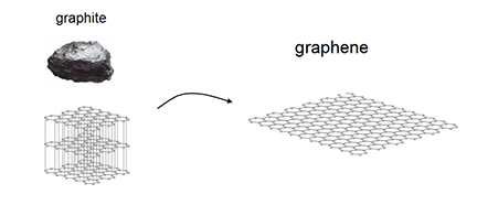
The only problem is, the process of creating graphene is a difficult one. Graphene sheets are grown individually in a chemical vapor deposition (CVD) tube. This is costly, time consuming and produces an extremely small amount of graphene per batch. An alternative approach being studied today is the process of chemical exfoliation of graphite (multi-layers of graphene in a solid, 3D state). In this process, graphite can be converted to graphene-oxide with functional oxygen groups bonded to the layers, enabling them to be exfoliated from the solid with just water. An illustration of the production of graphene from graphite is shown in Figure 1. The graphene-oxide sheets are not electrically conductive in the way that graphene is, however the removal of the oxygen functional groups improves conductivity.
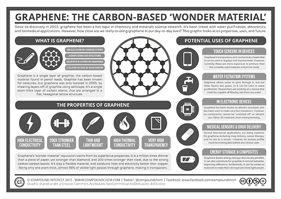
In laboratory environments, engineers and scientists use a high-temperature annealing process to reduce the functional groups on the graphene-oxide sheets and improve conductivity. If it is possible to obtain graphene-like conductivity through this process, this may open the door to commercial manufacturing of graphene-based fibers, which is a major step toward functional organic electronic circuitry. See Figure 2 for a summary of the remarkable properties of graphene.

Procedure
Background
Students will produce multiple layers of graphene in a solid state using the process of chemical exfoliation on graphite. Students will prepare graphite and examine how processing parameters influence the properties of the materials produced. Student groups will pretend to be engineers working for a company, where their job an engineers is to design a process for fabricating graphite fibers that are optimized for conductivity.
- Provide students with the Pre-Assessment questions and Pre-Activity Homework. During the classroom period introduce students to the topic of nanomaterials and semiconductors using the video links provided in the materials list.
- Give students a copy of the Student Handout.
- At the conclusion of the engineering activity students may complete one or both of the post-assessment: Post-Activity Assessment Option 1 and/or Post-Activity Assessment Option 2.
Before the Activity
- Have students prepare in advance (directions provided below and on the Student Handout):
- Pour 2 g powdered sodium alginate should be poured into blender for every 100 ml of warm water. The powder must be poured slowly while blending to yield the best results.
- Food coloring can be added at this stage (optional; adding food color will not affect the properties of the design).
- Refrigerate the mixture overnight to deter bacterial growth.
With the Students
- Present the fundamentals of organic electrically conducting materials and smart materials as described in the Introduction/Motivation Section. In addition, allow students to watch educational videos on the topics of eTextiles and graphene provided in the Materials List website links. For reference, these video links are provided below.
- After introducing the topic of organic materials, provide students with the pre-assessment discussion questions (see Assessment below) and the Pre-Activity Homework. In these pre-laboratory activities, students will be asked to research about the wearables technology industry prior to conducting the laboratory work. These assignments will provide students with the opportunity of working together in teams to gather information to support the activity. The homework assignment requires each group to create a 5-slide presentation that explains, with pictures, the reasons by which traditional electronics are not optimal for eTextile use. Examples include the cost of processing silicon for transistors in electronics, the use of rare earth metals, the difficulties in recycling, the fragility, cost and weight of existing devices, etc. Students will be researching these on their own with some initial guidance from the teacher. Of the 5 slides, first slide can be title slide and the last slide should include references/sources. These slides can be included in the Post-Activity Assessment Option 2.
- Resource web links and assignment details are provided in the attachments to the activity. These web links are also provided below.
- Once students have completed the pre-activity assignments, hand out the Student Handout that introduces them to the laboratory activity. The activity comprises a materials engineering design challenge where students will create a procedure for producing optimized organic fiber. The procedure for fabrication of the organic fibers is provided in the student handout. This handout provides details pertaining to the factors that influence the fiber and guides students through the design process for exploring the influence of the parameters on the conductivity of the fibers. The primary goal of the activity is to refine a procedure for the creation of organic, graphite-based fibers, to minimize resistivity and fiber width.
- Explain to the students that the process that they will use to make the fibers is based on a “snake goo” recipe that comprises sodium alginate and water that is extruded into calcium chloride in order to make snakes or “fibers”. The addition of graphite in varying amounts allows the fibers to be relatively conductive, where the addition of more graphite leads to the more conductive fibers that can have resistance as low as 30 kΩ. Students will document their findings related to the production process via inclusion of measurement data and an analysis of the data to demonstrate how they reached their conclusions regarding the optimal production parameters.
- Prior to conducting the laboratory with the students describe the safety of the working materials:
- Sodium alginate is a food-additive and is harmless if ingested.
- Graphite can be dangerous if inhaled or comes in contact with the eyes, so precautions should be taken in its handling. Ensure graphite is scooped carefully and not poured.
- Food coloring may be used to color the alginate and is safe for ingestion.
- A summary of the student handout material to be presented by the teacher is provided below during steps 8 – 20.
- The goal of the laboratory is to refine a procedure for the creation of organic, graphite-based fibers that minimizes fiber resistivity and width. The design constraints are that the fibers must be a minimum of 3 cm in length and optimized for minimum resistivity and diameter, where they will be measuring the resistance of each fiber they produce and calculating the resistivity using Equation 1, which is provided in step 9.
- Students will be using a sodium-alginate base solution, adding varying amounts of graphite. They will use the resulting mixture in a wet-spinning technique to extrude fibers into a coagulation bath of calcium chloride. Students will vary the amount of graphite and may also vary the thickness of the sodium alginate or the concentration of calcium in the CaCl2 bath. The resistance of the fibers will be measured over a length along the “fiber” using a multimeter set on the 200kΩ setting for resistance. Students will then measure length and diameter of each “fiber”. Length (l), cross-sectional area (A) and resistance (R) will be used to calculate resistivity using the formula:
ρ=RA/l
- To make the fibers:
- Prepare the calcium bath with deionized water and 6 g CaCl2 flakes. If lab grade is not available, road deicing pellets can be used.
- Mix the graphite into the sodium alginate (prepared previously), using a spoon or wooden spatula. Do not pour, and avoid any handling of graphite that will result in airborne particles.
- Draw sodium alginate-graphite mixture into a plastic 5 ml pipette or a plastic syringe.
- Extrude sodium alginate/graphite mixture at a constant rate into the calcium solution (prepared in step 10 a).
- Use a clean spoon, glass stirring rod or other to remove the “fiber” out of the calcium bath solution. Dry fibers on a paper towel.
- Record observations in a laboratory notebook and/or laboratory student handout sheet.
- Testing the fibers:
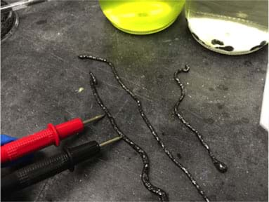
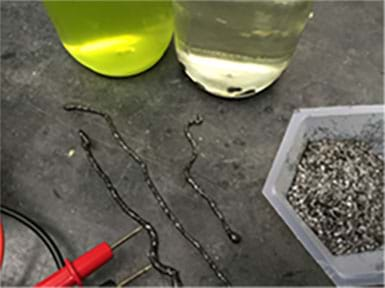
- To test the resistance, use a multimeter set on 200 kΩ and be sure the tips of the leads are inserted into (not on top of) the fiber at a predetermined or measured length. The measurement of the graphite fibers is shown in Figure 3.
- The measured length (l) of the fiber, for use in calculating resistivity (r), will be the distance between the leads when measuring resistance (R).
- To measure the diameter of the fiber, use a millimeter ruler, light microscope set on the lowest setting with a transparent ruler positioned on the stage.

- Analysis and Optimization:
- Complete the table on the worksheet (provided in the Student Handout) and calculate resistivity for each fiber created and measured. Create at least 5 fibers.
- Factors to be varied:
- fiber width
- graphite concentration
- calcium concentration (although the level of calcium ions in the bath will reduce after each fiber is created)
- viscosity as reflected through the amount of water used in producing the sodium alginate solution
- When students review their data, remind them that the goal is to optimize for smallest resistivity. As they create and test fibers, determine what factor(s) are responsible for lowest resistivity and try to optimize them, given the constraints and the availability of their resources.
- The engineering design will be completed when students: 1) Have produced a fiber with lowest resistivity, and 2) explain what factors lead to this optimal state.
Vocabulary/Definitions
anneal: To heat a material (usually metal or glass) and allow it to cool slowly, in order to remove internal stresses and toughen it.
conductivity: The property of a material that conducts electricity; inverse of resistivity.
electrical resistance: The ability of a material to resist the flow of electrons, measured in ohms.
graphene: A layer of carbon atoms in a single sheet that is one atom thick.
graphite: Layers of carbon assembled in a 3D structure; coal is an example of a graphite structure.
nanoscale: A term that refers to objects that are 1 billionth of a meter in size; used to measure scales at the atomic level.
organic: Carbon-based material or molecule.
organic electronics: Field of materials science in which polymers and other small molecules are studied for conductivity and other properties.
resistivity: The property of a material that resists electric current; inverse of conductivity.
Assessment
Pre-Activity Assessment
Discussion Questions: Solicit, integrate and summarize student responses. Have students discuss the following questions together in small groups.
- What is graphene, and what makes graphene different from graphite? (Answer: Graphene is a one-atom-thick (2D) layer of graphite (3D).)
- Why is graphene considered a “wonder material”? (Answer: Because it has remarkable properties in electrical resistance, thermal conductivity, transparency, strength and flexibility)
- Why is calcium used in the graphene coagulation bath? (Answer: Because it has a 2+ charge and can bond with two graphene sheets at a time, effectively connecting them to one another. (In this lab, the calcium will also crosslink the sodium alginate polymer chains together, providing a network that suspends the graphite particles.))
- What is the biggest challenge to using graphene in commercial processing at this time? (Answer: Graphene is extremely difficult to make in large quantities.)
Homework: The Pre-Activity Homework is provided for students to complete prior to conducting the laboratory activity in the classroom.
Post-Activity Assessment
Post-Assessment: Two options for post-activity assessment are provided:
The first option provides instructions for producing a final report: Post-Activity Assessment Option 1. The second option includes instructions for a final presentation: Post-Activity Assessment Option 2.
Safety Issues
Safety of the working materials:
- Sodium alginate is a food-additive and is harmless if ingested.
- Graphite can be dangerous if inhaled or comes in contact with the eyes, so precautions should be taken in its handling. Ensure graphite is scooped carefully and not poured.
- Wear gloves, wipe area down surfaces afterward with a wet cloth.
- Food coloring may be used to color the alginate and is safe for ingestion.
Activity Extensions
Have students complete the both post-activity assessment options.
Subscribe
Get the inside scoop on all things Teach Engineering such as new site features, curriculum updates, video releases, and more by signing up for our newsletter!More Curriculum Like This

Students are introduced to the technology of flexible circuits, some applications and the photolithography fabrication process. They are challenged to determine if the fabrication process results in a change in the circuit dimensions since, as circuits get smaller and smaller (nano-circuits), this c...
References
Chemical Snakes, accessed June 18, 2016, http://www.dynamicscience.com.au/tester/solutions1/chemistry/chemicaldemos/chemicalsnakes.htm
Cute Circuit: Wearable Technology, Vision and History, accessed June 18, 2016,
http://cutecircuit.com/wearable-technology/#after_full_slider_1
Higgins, Stuart. “Three Ways Organic Electronics Is Changing Technology as We Know It.” The Conversation, September 10, 2016, theconversation.com/three-ways-organic-electronics-is-changing-technology-as-we-know-it-63287
Kennemer, Quentyn; Phandroid, May 29th, 2015, http://phandroid.com/2015/05/29/project-jacquard-smart-clothes/
PSFK Innovation Debrief: The Future of Wearable Tech, Jan 8, 2014, LinkedIn Slideshare, accessed June 18, 2016,
http://www.slideshare.net/PSFK/psfk-future-of-wearable-tech-summary-presentation
Welcome to Project Jacquard, Google ATAP. YouTube. May 29, 2015, https://youtu.be/qObSFfdfe7I
Copyright
© 2020 by Regents of the University of Colorado; original © 2019 Rutgers UniversityContributors
Mariel Kolker; Kimberly Cook-Chennault; Jason KupferbergSupporting Program
Rutgers University Research Experience for Teachers in Engineering – Green Energy TechnologyAcknowledgements
This curriculum was based upon work supported by the National Science Foundation under Research Experience for Teachers in Engineering (RU RET-E) for Green Energy and Technology grant no. 1407266. Any opinions, findings, and conclusions or recommendations expressed in this material are those of the authors and do not necessarily reflect the views of the National Science Foundation.
Last modified: September 2, 2020


User Comments & Tips