Quick Look
Grade Level: 10 (9-12)
Time Required: 1 hour
Expendable Cost/Group: US $0.50 This activity uses some non-expendable (reusable) items; see the Materials List for details.
Group Size: 3
Activity Dependency: None
Subject Areas: Computer Science, Science and Technology
Summary
Students work as if they are electrical engineers to program a keyboard to play different audible tones depending on where a sensor is pressed. They construct the keyboard from a soft potentiometer, an Arduino capable board, and a small speaker. The soft potentiometer “keyboard” responds to the pressure of touch on its eight “keys” (C, D, E, F, G, A, B, C) and feeds an input signal to the Arduino-capable board. Each group programs a board to take the input and send an output signal to the speaker to produce a tone that is dependent on the input signal—that is, which “key” is pressed. After the keyboard is working, students play "Twinkle, Twinkle, Little Star" and (if time allows) modify the code so that different keys or a different number of notes can be played.Engineering Connection
Electronics and sensory equipment are ubiquitous across all engineering fields. Electrical and mechanical engineers in particular design buttons and knobs as sensors that give output to users. For example, the “beeps” that microwave buttons make when pressed serve as cues to make the device more user-friendly, which is an important design consideration when creating consumer products.
Learning Objectives
After this activity, students should be able to:
- Describe potentiometers and provide examples of real-world applications for them.
- Connect electrical components and troubleshoot in case of unexpected results.
- Use “for loops” and “if statements” to carry out a program.
Educational Standards
Each TeachEngineering lesson or activity is correlated to one or more K-12 science,
technology, engineering or math (STEM) educational standards.
All 100,000+ K-12 STEM standards covered in TeachEngineering are collected, maintained and packaged by the Achievement Standards Network (ASN),
a project of D2L (www.achievementstandards.org).
In the ASN, standards are hierarchically structured: first by source; e.g., by state; within source by type; e.g., science or mathematics;
within type by subtype, then by grade, etc.
Each TeachEngineering lesson or activity is correlated to one or more K-12 science, technology, engineering or math (STEM) educational standards.
All 100,000+ K-12 STEM standards covered in TeachEngineering are collected, maintained and packaged by the Achievement Standards Network (ASN), a project of D2L (www.achievementstandards.org).
In the ASN, standards are hierarchically structured: first by source; e.g., by state; within source by type; e.g., science or mathematics; within type by subtype, then by grade, etc.
International Technology and Engineering Educators Association - Technology
-
Students will develop an understanding of the core concepts of technology.
(Grades
K -
12)
More Details
Do you agree with this alignment?
-
Students will develop abilities to use and maintain technological products and systems.
(Grades
K -
12)
More Details
Do you agree with this alignment?
-
Apply appropriate methods to diagnose, adjust, and repair systems to ensure precise, safe, and proper functionality.
(Grades
9 -
12)
More Details
Do you agree with this alignment?
-
Analyze the stability of a technological system and how it is influenced by all the components in the system, especially those in the feedback loop.
(Grades
9 -
12)
More Details
Do you agree with this alignment?
Materials List
Each group needs:
- 5 jumper wires; such as 7-inch, M/M, 30AWG from https://www.sparkfun.com/products/11026
- 1 mini speaker; such as PC mount 12 mm 2.048 kHz mini speaker from https://www.sparkfun.com/products/7950
- 1 10-kΩ resistor; such as resistor 10k ohm 1/6th watt PTH from https://www.sparkfun.com/products/8374
- 1 50-mm soft membrane potentiometer; such as SoftPot SEN-08680 ROHS https://www.sparkfun.com/products/8680
- 1 breadboard; such as https://www.sparkfun.com/products/12002
- 1 SparkFun RedBoard programmed with Arduino, for $20 at https://www.sparkfun.com/products/12757
- ruler
- fine-point sharpie or other pen
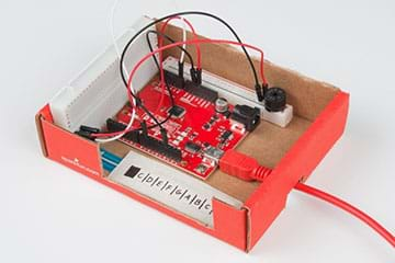
- (optional, but recommended) small cardboard box to house the final project; ~5 x 3.5-inches; see Figures 5 and 6
- (optional) SIK Keyboard Code, one per group
To share with the entire class:
- scissors
- X-Acto® knife
- masking tape, double-stick tape or other adhesive
- (optional) projector to show Visual Aid
Worksheets and Attachments
Visit [www.teachengineering.org/activities/view/spfun_keyboard_activity1] to print or download.Pre-Req Knowledge
It is highly recommended that students are familiar with Arduino and circuitry. If self-coding, students should also have experience with “for loops” and “if statements.”
Introduction/Motivation
Programmable electronics are everywhere—from your phone to cars to entertainment—and even healthcare! Many devices make an audible chime when a component is plugged in or a button is pressed, such as the noise your phone makes when you plug in its charger or the beeps that microwave buttons make when pushed. Can you think of any other examples? (Listen to student responses.)
Today you will work as if you are electrical engineers with the task to program a horn to play different tones depending on where a sensor is pressed. You will use a soft potentiometer that responds to the pressure of touch and feeds an input signal to an Arduino-capable board. Pressing along the soft potentiometer produces different voltages depending on the depression location (that is, where you press). For this activity, we will press just one location at a time. The resulting voltage travels along connecting wires from the potentiometer to a SparkFun RedBoard. The programmable RedBoard then reads the voltage supplied by the potentiometer and responds to the supplied voltage however the board is programmed.
For this activity, the board transforms the read voltage into a tone. Then an electrical impulse is sent from the RedBoard to the speaker; the impulse will vary depending on the potentiometer voltage and RedBoard programming. Then the electrical impulse sent to the speaker causes the electromagnet in the speaker to drive a thin metal sheet, which produces a tone. Let’s get started!
Procedure
Background
The program works by reading an incoming value from the potentiometer. If the read value is in the allowable range, then the program decides to play a note. “If statements” are used to divide the read potentiometer value into different notes. If the potentiometer value is in the range of a certain note assignment, then the speaker for the programmed time value plays that note.
Before the Activity
- Gather materials and organize them by group for easy distribution and to prevent loss/theft of small components.
- Decide whether or not your students have the programming skill to write the code from scratch. If not, make copies of the SIK Keyboard Code, one per group.
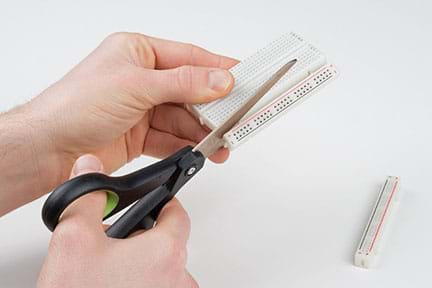
- Decide whether to cut the breadboards (see Figure 1) to better fit in the keyboard-housing boxes you gathered—or leave them intact.
- With the class, review polarized components, which are asymmetrical and can only be placed into the circuit one-way or the component will short and cease to function. The potentiometer is the only polarized component in this build. An arrow on the potentiometer lead indicates the negative or grounded end.
- (optional) Prepare a projector to show the class activity setup images, which are Figures 2 and 3, also provided in the Visual Aid. Alternatively, make a sketch on the classroom board.
With the Students
- Divide the class into groups of three and distribute the materials.
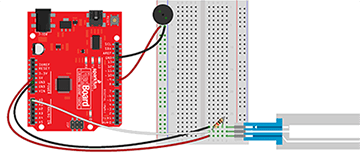
- Direct each group to connect its components to the breadboard and the RedBoard, as shown in Figure 2 (if you chose to leave the breadboards intact) or Figure 3 (if you chose to cut the breadboards). Project the visual aid for students to see; alternatively, sketch it out on the board. Tell students to pay close attention to the potentiometer. This component is polarized and must be connected as shown in order to function correctly.
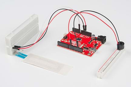
- Have students use rulers to mark 6-mm intervals on the touchable, silver area of the potentiometer, as shown in Figure 4, to make eight “keys.” Have them make a mark or fill in the first 6-mm portion, as it is not encoded to do anything. Next, start measuring from the breadboard end of the potentiometer. Mark each note on the keyboard. It is easiest to start in the key of C and label the eight keys C, D, E, F, G, A, B, C.
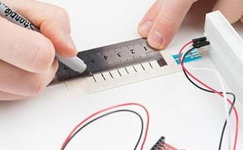
- The keyboard is now complete! Constructing a box to enclose the project is optional, but if doing so, go to the next step. If not using a box, skip to step 7.
- (optional housing box steps 5-6; see Figure 5) Have students use loops of tape (or other adhesive) to secure the breadboard to one side inside the box and the potentiometer to the inside bottom of the box. If using the cut breadboards, attach the smaller breadboard with the speaker opposite the potentiometer. Use a loop of tape on the back of the RedBoard is to secure it between the potentiometer and speaker.
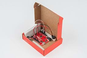
- If the housing boxes have lids, direct students to use scissors to remove them. Cut a notch on the right side of the box for the power cord to feed into the RedBoard. Also cut a larger notch on the sidewall along the potentiometer to give better access to the keys (see Figure 6).
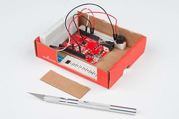
- Depending on the programming skill of your students, either have them write the code from scratch or give them the provided code handout. With the code in the editor, upload it to the RedBoard. After the code is uploaded, have students try pressing along the potentiometer to make the speaker produce a tone. If no sound is produced, suggest that students double-check their wiring to make sure everything is plugged in. Since many of the components are small, this is often required.
- After the keyboard is working, tell students to try playing Twinkle, Twinkle, Little Star (or another simple song of your choice). Then, if time allows, have students modify the code so that different keys, or a different number of notes can be played.
Vocabulary/Definitions
ground (electricity): The reference point in a circuit that voltages are measured against.
key (music): A scale or group of pitches that a musical piece is based on.
microcontroller: A small computer on a single chip.
pin: A physical connection on a microcontroller.
potentiometer: A variable resistor in which the resistance provided changes depending on where along the potentiometer it is pressed.
Assessment
Pre-Activity Assessment
Brainstorming: As a lead-in to the activity and to gauge what students know about the topic, ask the class a few questions to get them to think about what’s happening “behind the scenes” in many of the beeping and buzzing objects in our everyday lives. Ask the students:
- How do electric keyboards and other electrical instruments work?
- How do button-based sounds work? For example, the beeps you hear when pressing microwave buttons.
- Can you think of any other examples?
Activity Embedded Assessment
Play a Song! Once keyboards are assembled and work, have students play songs using their keyboards. Something simple like Twinkle, Twinkle, Little Star is a good choice. Other songs and specific notes can be found online if students cannot figure out the notes by ear.
Post-Activity Assessment
Bigger and More Complicated Things! Have students think about more complex coding projects that they could carry out using Arduino-capable boards. Either make this a creative, hypothetical exercise, or if good and feasible ideas arise, turn this into an in-class project to be completed later. Students’ ideas reveal their depth of comprehension of the activity content.
Troubleshooting Tips
If no sounds are produced, double-check the wiring. Several of the components are small and misplaced wires prevent sound from being produced.
Activity Extensions
The SIK Keyboard Code is for C major and eight keys. To extend the project, have students modify the code or the spacing of the potentiometer. Or have them change the assigned frequency to potentiometer values to produce notes in different scales. See http://www.phy.mtu.edu/~suits/notefreqs.html as a good resource for mapping frequency to notes. Another idea is to have students make finer divisions along the potentiometer, and for example, produce 12 notes instead of eight.
Activity Scaling
- For lower grades, provide the SIK Keyboard Code to students.
- For higher grades, do not give students the code unless they are really struggling. Or give hints about which commands to use, but let students come up with the code on their own. Challenge students to program a different number of keys or program the keyboard in a key other than C major.
Additional Multimedia Support
A good resource for mapping frequency to notes is B.H. Suits’ Frequencies for equal-tempered scale, A4 = 440 Hz website; summer 1998; Physics of Music – Notes, Physics Department, Michigan Technological University; http://www.phy.mtu.edu/~suits/notefreqs.html
Subscribe
Get the inside scoop on all things Teach Engineering such as new site features, curriculum updates, video releases, and more by signing up for our newsletter!References
Introduction to the SparkFun Inventor’s Kit (SIK) Keyboard Instrument. Tutorials, SparkFun Electronics. Accessed January 2017. https://learn.sparkfun.com/tutorials/sik-keyboard-instrument
Copyright
© 2017 by Regents of the University of Colorado; original © 2014 SparkFun EducationContributors
Shawn Hymel, SparkFun; Lauchlin Blue, University of Colorado BoulderSupporting Program
SparkFun EducationLast modified: January 12, 2019


User Comments & Tips