Quick Look
Grade Level: 11 (11-12)
Time Required: 4 hours 15 minutes
(five 50-minute class periods)
Expendable Cost/Group: US $1.00 This activity uses some non-expendable (reusable) items such as Arduino® electronics; see the Materials List for details.
Group Size: 2
Activity Dependency:
Subject Areas: Computer Science, Physics, Problem Solving, Science and Technology
NGSS Performance Expectations:

| HS-ETS1-2 |
Summary
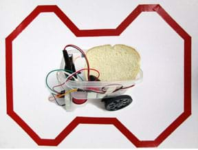
Students are challenged to design and program Arduino-controlled robots that behave like simple versions of the automated guided vehicles engineers design for real-world applications. Using Arduino microcontroller boards, infrared (IR) sensors, servomotors, attachable wheels and plastic containers (for the robot frame), they make "Lunch-Bots." Teams program the robots to meet the project constraints—to follow a line of reflective tape, make turns and stop at a designated spot to deliver a package, such as a sandwich or pizza slice. They read and interpret analog voltages from IR sensors, compare how infrared reflects differently off different materials, and write Arduino programs that use IR sensor inputs to control the servomotors. Through the process, students experience the entire engineering design process. Pre/post-quizzes and coding help documents are provided.Engineering Connection
Engineers design robots that are able to manage inventory within offices and warehouses. Robots can efficiently sort and retrieve parts from warehouse shelves during manufacturing processes, deliver mail in office buildings and automatically deliver medications in hospitals. To accomplish these tasks and avoid obstacles, robots need to detect information about their working environments. This can be accomplished by creating designated paths on the floor using embedded wiring or sensors that guide the robots through a series of turns to predetermined delivery locations.
Learning Objectives
After this activity, students should be able to:
- Use an Arduino to read and interpret analog voltages from IR sensors.
- Compare and contrast how infrared reflects differently off of different types of materials.
- Plan the design of a simple robot and follow the steps of the engineering design process to create a robot that has a compartment for computer hardware, battery and cargo, two servos with wheels that act as drive motors, a front support leg/caster and two IR sensors that can detect reflections.
- Write Arduino programs that use input from IR sensors to control servomotors.
- Write Arduino programs that direct a robot to follow reflective tape along the ground by making decisions based on voltage values from IR sensors.
- Explain how a simple, automated guided vehicle works.
Educational Standards
Each TeachEngineering lesson or activity is correlated to one or more K-12 science,
technology, engineering or math (STEM) educational standards.
All 100,000+ K-12 STEM standards covered in TeachEngineering are collected, maintained and packaged by the Achievement Standards Network (ASN),
a project of D2L (www.achievementstandards.org).
In the ASN, standards are hierarchically structured: first by source; e.g., by state; within source by type; e.g., science or mathematics;
within type by subtype, then by grade, etc.
Each TeachEngineering lesson or activity is correlated to one or more K-12 science, technology, engineering or math (STEM) educational standards.
All 100,000+ K-12 STEM standards covered in TeachEngineering are collected, maintained and packaged by the Achievement Standards Network (ASN), a project of D2L (www.achievementstandards.org).
In the ASN, standards are hierarchically structured: first by source; e.g., by state; within source by type; e.g., science or mathematics; within type by subtype, then by grade, etc.
NGSS: Next Generation Science Standards - Science
| NGSS Performance Expectation | ||
|---|---|---|
|
HS-ETS1-2. Design a solution to a complex real-world problem by breaking it down into smaller, more manageable problems that can be solved through engineering. (Grades 9 - 12) Do you agree with this alignment? |
||
| Click to view other curriculum aligned to this Performance Expectation | ||
| This activity focuses on the following Three Dimensional Learning aspects of NGSS: | ||
| Science & Engineering Practices | Disciplinary Core Ideas | Crosscutting Concepts |
| Design a solution to a complex real-world problem, based on scientific knowledge, student-generated sources of evidence, prioritized criteria, and tradeoff considerations. Alignment agreement: Analyze data using tools, technologies, and/or models (e.g., computational, mathematical) in order to make valid and reliable scientific claims or determine an optimal design solution.Alignment agreement: Create a computational model or simulation of a phenomenon, designed device, process, or system.Alignment agreement: | Criteria may need to be broken down into simpler ones that can be approached systematically, and decisions about the priority of certain criteria over others (trade-offs) may be needed. Alignment agreement: | Models (e.g., physical, mathematical, computer models) can be used to simulate systems and interactions—including energy, matter, and information flows—within and between systems at different scales. Alignment agreement: |
International Technology and Engineering Educators Association - Technology
-
Students will develop an understanding of the attributes of design.
(Grades
K -
12)
More Details
Do you agree with this alignment?
-
Students will develop an understanding of engineering design.
(Grades
K -
12)
More Details
Do you agree with this alignment?
-
Students will develop an understanding of the role of troubleshooting, research and development, invention and innovation, and experimentation in problem solving.
(Grades
K -
12)
More Details
Do you agree with this alignment?
-
Students will develop abilities to apply the design process.
(Grades
K -
12)
More Details
Do you agree with this alignment?
State Standards
Michigan - Science
-
Design a solution to a complex real-world problem by breaking it down into smaller, more manageable problems that can be solved through engineering.
(Grades
9 -
12)
More Details
Do you agree with this alignment?
Michigan - Technology
-
use digital resources (e.g., educational software, simulations, models) for problem solving and independent learning
(Grades
9 -
12)
More Details
Do you agree with this alignment?
-
assess and solve hardware and software problems by using online help or other user documentation
(Grades
9 -
12)
More Details
Do you agree with this alignment?
-
participate in experiences associated with technology-related careers
(Grades
9 -
12)
More Details
Do you agree with this alignment?
Materials List
Each group needs:
- Arduino Uno – R3® (a microcontroller board), part # DEV-1121 at Sparkfun.com
- computer with Internet access, loaded with Microsoft Excel® and Arduino open source IDE software, free at https://www.arduino.cc/en/Main/Software
- 2 line-follower sensors, such as the SparkFun RedBot Sensor Line Follower, part # SEN-11769 at Sparkfun.com
- breadboard, part # PRT 12002 (self-adhesive, white) at Sparkfun.com
- 6 jumper wires, 6-inches (~15-cm) long, with male and female end connections, such as part # PRT-12794 at Sparkfun.com
- 6 jumper wires, 6-inches (~15-cm) long, with male end connections, such as part # PRT-12795 at Sparkfun.com
- 2 Parallax Continuous Rotation Servos, part # 900-00008 at Parallax.com
- 2 wheels that connect to the servomotors, SumoBot Wheel & Tire, part # 28109 at Parallax.com; this wheel fits directly on the spline of the servo
- 2 sheets white copy paper, 8.5 x 11 inches (22 x 28 cm)
- reflective tape, 1 x 12-inch (~2.5 x 30-cm) piece
- black electrical tape, .75 x 12-inch (~2 x 30-cm) piece
- USB A to B 6-foot cable; part # CAB-00512 at Sparkfun.com
- 9 volt to barrel jack adapter; part # PRT-09518 at Sparkfun.com
- 9 volt battery
- 1 (or more) plastic storage food containers or rectangular sandwich storage boxes no smaller than 3 cups (710 ml) in size; ask students to each bring a container from home; one container serves as the robot frame; use any additional containers to store project components as the robots are being constructed
- 1 robot support leg, an object to attach to the robot frame to serve as the third leg (in addition to the two wheels; see Figure 2); have students bring from home items such as small cups like a 3-ounce plastic Dixie®-type cup (~2.25-inches or ~6-cm tall; plastic cups are stronger and slide better than paper ones), plastic balls or ping pong balls (~1.5-inch or 4-cm diameter); upgrade alternative; a ball caster, such as the Omni-Directional Metal Ball Caster, part # ROB-00320
- double-sided tape or duct tape, 1.8 x 12-inches (~4.6 x 30-cm), to fasten components to the plastic container (robot frame)
- Remember Your Arduino Pre-Quiz and Lunch Is Served! Post-Quiz, one each per student
- Introduction to Arduino Handout, one per group
To share with the entire class:
- projector and computer with Internet access to show students an online video and other resources
- 1 white poster board, 24 x 36-inches (61 x 91-cm), on which to tape a test course (see Figure 4)
- reflective tape, for making the final test course on the poster board and to make each team's test sheets; such as 3M Scotchlite Reflective Striping Tape, Red, 1 x 50-foot roll at Amazon.com
- black electrical tape, for the teacher and students to mark stopping points on tape paths, such as 3M 88 Black Electrical Tape, 0.75 inches x 66 foot roll
- lunch food for Day 5, for the Lunch-Bots to carry and deliver on the final test day, such as bread slices, small sandwiches or small pizza slices
Worksheets and Attachments
Visit [www.teachengineering.org/activities/view/mis_sensor_lesson01_activity1] to print or download.Pre-Req Knowledge
Before beginning this activity, expect students to:
- Be familiar with infrared light and some of the various ways it is used in engineering (such as presented in the associated lesson).
- Be familiar with the Arduino microcontroller, know how to use software to write Arduino code and know how to download software onto the Arduino microcontroller.
- Be able to program a servomotor with various pulse widths to go clockwise, counter-clockwise and stop.
- Know how to use and mount electronic components onto an electronic breadboard and connect electronic components from a breadboard to an Arduino microcontroller.
Introduction/Motivation
(Be ready to show the class a short video, Automated Guided Vehicles at the Cleveland Clinic [1:47 minutes] at: https://www.youtube.com/watch?v=-c1n9dn7_iQ.)
What is the purpose of the AGV (automated guided vehicle)? (Answer: At the Cleveland Clinic, AGVs move supplies throughout the hospital campus.) What important feature of the AGV guides it to its destination? (Wait for student responses and if necessary, relate the AGV to a person following a sidewalk or a trail in a park and then stopping at a bench to rest. Answer: A magnetic grid placed under the flooring.) In order to deliver items, the AGV reacts to information provided from sensors buried in the floor.
AGVs are used for many different applications. Some are designed for use in industrial environments to move materials around a manufacturing facility or warehouse. Others are designed to deliver mail and supplies in hospital and office environments. They are mobile robots that follow markers, wires or magnets in a floor, or use vision or lasers to move materials around a large facility or campus.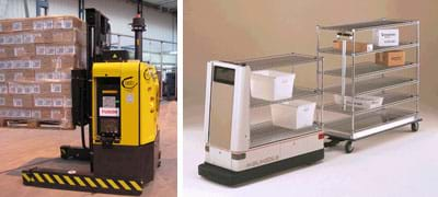
Over the course of the next couple of days you are going to design a robot similar to an AGV that uses an IR sensor to follow a line of tape on the floor. Your "Lunch-Bot" robot will carry a package and stop at a specified location—just like the AGVs in the video. For this activity, the package is food and if your robot does not stop correctly to deliver it to you, you will miss out on eating your lunch!
Procedure
Before the Activity
- Gather materials and make copies of the Remember Your Arduino Pre-Quiz and Lunch Is Served! Post-Quiz, one each per student, and the Introduction to Arduino Handout, one per group.
- Decide how to divide the class into groups. Groups of two are best if you have enough equipment to support that many teams.
- Ask students to each bring in a small plastic rectangular sandwich storage box or small plastic food storage containers (see Figures 2 and 3 for examples). Any extra containers can be used to store components as the robots are constructed.
- Also, ask students to bring from home small plastic cups or balls to serve as the third support legs (in addition to the two wheels) for the plastic container robot frames (see Figures 2 and 3)—to prevent the nose of the robot from dragging on the floor.
- Familiarize yourself with Arduino by reviewing the Introduction to Arduino Handout, the Arduino Tutorial at http://www.ladyada.net/learn/arduino/lesson1.html and the information on servos at https://www.jameco.com/Jameco/Products/ProdDS/283039%20Manual.pdf.
- Become familiar with the IR sensor and learn how to read values from it with the Arduino serial monitor. Realize that the 5 volt analog values from the IR sensor span a range from 0 to 1023 due to the 8 bit conversion of analog values to digital values on the Arduino and due to the design of the IR circuit; smaller numbers imply more surface reflection.
- Construct your own Lunch-Bot and program it to follow a taped line with 45° turns in order to understand the challenges students may face in keeping the robot on track. If you have trouble programming the robot, consult the IR Sensor Calibration Code, Stopped Motor Code and Tape Follower Code. Also decide whether you want to make these three code documents available to your students in digital or hardcopy.
- Prepare the computers by installing the Arduino software on them.
- Prepare for each group two pieces of paper with black electrical tape and red reflective tape as shown in Figure 1. Sheet 1 (left) has two one-inch pieces of tape adhered to it—one red reflective tape and the other black electrical tape. Sheet 2 (right) has two six-inch pieces of red tape touching end-to-end with one piece angled at 45° to the other, and a one-inch piece of black tape over a spot on the red tape. Student groups use these test sheets to (left sheet) study the IR sensor output above different surfaces, and then (right sheet) develop and test software to guide the robot along a path and stop the robot at a predetermined location (where the short black tape crosses the red line). Note: The hardware used in this activity makes it too difficult to turn a robot at a sharp 90° angle.
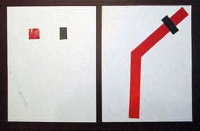
Figure 1. Example test sheets to make in advance. - For Day 1, be ready to show the class a short video, Automated Guided Vehicles at the Cleveland Clinic (1:47 minutes) at: https://www.youtube.com/watch?v=-c1n9dn7_iQ.
- For Day 4, prepare a robot challenge course using red reflective tape on a 2 x 3-foot piece of white poster board, such as the example shown in Figure 4. For the course route, make a continuous loop path consisting of left and right turns, each no greater than 45°, along with straight sections, each at least 6 inches long so the robot has a chance to straighten out before the next turn.
- For Day 5, arrange to have some sort of food, such as bread slices, for the Lunch-Bots to carry and deliver as the concluding test. For fun, consider ordering pizza for the class and cutting it into extra small slices; give each team a slice to carry on its robot for the test.
With the Students—Day 1: Introduction, Pre-Quiz and Research
- Present the Introduction/Motivation content to the class, showing them a short video about AGVs.
- Divide the class into groups of two students each. Have groups sit at their computers.
- Direct the groups to review the Introduction to Arduino Handout, the Arduino tutorial at http://www.ladyada.net/learn/arduino/lesson1.html and the servos information and specs at https://www.jameco.com/Jameco/Products/ProdDS/283039%20Manual.pdf.
- Hand out the pre-quiz. Direct students work with their partners to answer the questions as best as they can. Tell them you will collect the quiz in five minutes.
- Remind students that they previously learned how infrared (IR) sensors work. Project the following online document so that the class can see: What Is an IR Sensor? Principles of Operation at http://www.education.rec.ri.cmu.edu/content/electronics/boe/ir_sensor/1.html. Tell students: Remember, when no object is present, no IR is detected by the sensor. When an object is present, an amount of IR is reflected back to the sensor; the amount reflected depends on how reflective the surface is.
- Project the following circuit schematic found at https://cdn.sparkfun.com/datasheets/Sensors/Infrared/RedBot_Line_Sensor.pdf. Tell students: Today I will give you a circuit that has both the IR LED emitter and a detector packaged together on one circuit. Take a look: The circuit power of 5 V is on pin 2, ground is pin 1 and the sensor output is pin 3. This circuit will be used to guide the Lunch-Bots.
- Tell the students: Today's goal is for you to study how well IR reflects off of red reflective tape and black electric tape, compared to plain white paper. Keep in mind that what you learn will guide you in placing your sensors correctly on the robots you design. You are acting as engineers by testing and gathering data about how well IR is detected at different heights, which you will use later to program your robot to follow the tape path or stop. In your study, collect data that relates the output values of the sensor to the height of the sensor from the surface below it.
- Hand out the line-follower sensors, two sensors per Lunch-Bot. Direct the groups to interface the IR sensors to their Arduinos.
- Pass out the first test sheets (the left sheet in Figure 1). Tell students: You will need to complete a study to help you understand how to detect the red tape edge so that your robot stays on course and how to detect the black tape to stop the robot.
- Give students time to explore the output of the IR circuit at different heights above the red and black tape, compared to white paper. Tell students: Use the serial monitor in the Arduino software to continuously view the output of your sensor as a function of height. Record at least five data points for each type of tape and for plain white paper. As needed, make use of the IR Sensor Calibration Code. Create an Excel® data table that shows the output of the sensor at different heights for the red tape, black tape and white paper. Then turn in to me the results of your study.
With the Students—Day 2: Design Challenge, Brainstorming, Design and Construction
- Introduce the engineering design challenge: Today you are going to act as robotics engineers who are in charge of designing a robot to deliver material to a specific location in a manufacturing plant. Your "package" is your lunch and the robot must follow a path of red reflective tape and stop in front of you over a black piece of tape. Your goal for today is to assemble your Lunch-Bot so that it is ready to be programmed tomorrow.
- Remind students: In yesterday's activity, you learned how the output of the IR sensor circuit changes based on the reflection off of a surface. Now, your goal is to use the plastic lunch container and the cup or ball you brought in, two servos with wheels, two IR sensors, a breadboard and the Arduino and battery to construct a Lunch-Bot. Design the Lunch-Bot to follow a piece of reflective tape along the floor and stop in front of you.
- Tell students: Draw sketches of your robots that detail the component locations and show it to me before you begin construction. Then give groups ~10 minutes to complete a simple sketch and show and explain it to you before they any assembly. Mention some considerations:
- Decide where to place the servos with their attached wheels (see Figure 2).
- Think about how you are going to use the cup or ball you brought in from home to prevent the nose of the robot from dragging on the floor.
- Based on what you learned yesterday, decide where and how to mount the infrared sensor onto the breadboard in order to detect and follow a piece of reflective tape on the floor under the robot. It takes two sensors to steer the robot left and right.
- Think about where to place the Arduino and all of the components to maximize carrying capacity.
- Before students begin mounting any components, direct them to wire their two servos to the Arduino and calibrate them to stop. Make available the Stopped Motor Code and have students in each group show you that they can put each servo in a stopped mode; to do this, they may need to adjust the potentiometer screw on the servo so that it does not turn or vibrate when the servo receives a 1.5 ms pulse. Give them ~25 minutes to complete this task and practice writing software to rotate the servo clockwise and counter-clockwise. For additional information, refer to the servos information and specs at https://www.jameco.com/Jameco/Products/ProdDS/283039%20Manual.pdf.
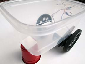
Figure 2. A partially constructed Lunch-Bot. In this design, a plastic cup serves as a front support leg. - After students calibrate their servos, have them assemble their Lunch-Bots, which includes using tape to fasten components to the robot frames (the plastic food containers). See Figure 3 for an example completed Lunch-Bot.
- Mention the deadline: Today, you need to finish assembling your Lunch-Bots so that they can be programmed tomorrow.
- Give students the balance of the class period to assemble their robots.
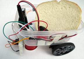
Figure 3. An example completed Lunch-Bot.
With the Students—Day 3: Programming and Movement Test Sheets
- Give each group a second test sheet (the right sheet in Figure 1).
- Tell students: Today's goal is to program your Lunch-Bot to follow the tape and turn along the test path.
- Tell students: Go to the following website to review how to program the servos to go clockwise or counter-clockwise: https://www.jameco.com/Jameco/Products/ProdDS/283039%20Manual.pdf.
- To check student understanding, ask:
- How should I run the servo speeds and directions so that the robot moves forward as straight as possible? (Answer: Run both motors at the same speed, but in opposite directions since they are on opposite sides of the platform.)
- Which wheel do I have to stop in order for the robot to turn left? (Answer: The wheel on the left side.)
- How can I get the robot to turn right? (Answer: Stop the right wheel.)
- When you are confident in student answers, direct them to start programming. Remind students that they have experience reading sensor values from the IR circuit from the first day, and they (ideally) have prior experience in programming the Arduino to control servomotors to rotate clockwise, counter-clockwise and stop. Encourage students to be sensible when developing their software and make decisions based on sensor values to ensure that their robots steer left or right, or move straight ahead following the tape.
- Give students the remainder of the class to program their robots. If students have trouble developing code for the robot, consider giving them hints from the Tape Follower Code.
With the Students—Day 4: Programming and Challenge Course
- Tell students: The robot challenge course consists of straight paths and 45° turns (making a sharp 90° turn is difficult since both sensor outputs change simultaneously, stopping the robot). Remember, you need to figure out how to stop your robots at a predetermined spot along the course! To accomplish the task, use a 2-inch piece of black electrical tape placed over the reflective tape path (this changes the sensor outputs and stops the robot).
- Show students the challenge course, the red tape route on white poster board (such as the example shown in Figure 4), and place it at a designated location in the classroom.
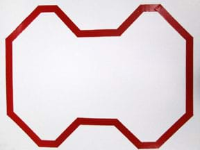
Figure 4. An example robot test course. - At their desks, have groups test their software using the test sheets that only have 45° turns. Have teams confirm that their robots can move, turn (without veering off-course) and stop.
- Then have teams test their final robot designs on the classroom challenge course (see Figure 4) to make sure the robots stop where intended.
With the Students—Day 5: Lunch is Served Final Test and Post-Quiz
Give students ~30 minutes to perfect their robot designs, watch other robots on the course, run their own robots on the course, and complete the post-quiz. Each group's robot is tested on the challenge course while other students observe, paying attention to the various robot designs and how successful they are at completing the course and stopping at predetermined locations.
- Say to the class: By now, every team should have a working robot. Today your objective is to get your robot to successfully complete the test course at least twice while carrying and delivering an object—your lunch! For the test, I will give you food that your Lunch-Bot must carry and deliver to a point on the course that I select.
- For each team's final Lunch-Bot test:
- The teacher places a 6-inch piece of black electrical tape (the stopping mechanism) across the reflective tape and perpendicular to it at a point of his/her choosing.
- Call up a team to demonstrate its robot.
- Lay a slice of bread or pizza onto the robot cargo hold.
- Have the team start its robot as the rest of the class watches.
- Prompt students to pay attention to note the robot features that make each robot successful or unsuccessful in meeting the challenge.
- Move on to test the next robot.
- As necessary, assist students with their hardware and software so that teams are successful in delivering the food.
- Administer and collect the post-quiz.
Vocabulary/Definitions
Arduino: An open-source platform used for building electronics projects. Arduino consists of both a physical programmable circuit board (a microcontroller) and a piece of software (integrated development environment, IDE) that runs on a computer to write and upload computer code to the physical board. Source: Sparkfun
Arduino serial monitor: An Arduino software tool that enables continuous data (such as output values from sensors) display on a computer monitor.
automated guided vehicle: A mobile robot that follows markers, wires or magnets in a floor, or uses vision or lasers to move materials around a facility or campus.
circuit ground: The negative side of a circuit. The return path for electric current.
circuit power: The voltage necessary to power a circuit.
electrical circuit: A collection of electronic components that performs a specific function.
infrared sensor: An electronic device that emits and detects infrared radiation in order to sense the surrounding environment. Also called IR sensor.
light-emitting diode: An electronic device (semiconductor) that gives off light of specific wavelengths. Abbreviated as LED.
sensor output: An output pin on a circuit from where sensor values are measured.
servomotor: A rotary actuator to control angular position of a shaft. It can rotate any number of degrees in the clockwise and counter-clockwise directions.
SparkFun line-follower circuit: A circuit that combines an infrared (IR) LED and a photo light sensor; used to measure surface reflection.
Assessment
Pre-Activity Assessment
Pre-Quiz: On Day 1, when mentioned in the Procedure section, have student pairs complete the four-question Remember Your Arduino Pre-Quiz as best as they can. Review students' answers to assess their level of understanding about Arduinos, IR sensors and servomotors.
Post-Activity Assessment
Post-Quiz: After the activity, administer the four-question Lunch is Served! Post-Quiz. Review students' answers to gauge their depth of understanding about AGVs, how they programmed their robots to follow a line and stop, and their observations of successful Lunch-Bot features.
Investigating Questions
- (Ask at the beginning of the activity.) Who can tell me some of the steps of the engineering design process? And in what order they usually happen to guide engineers as they create new products and systems. (Introduce or review the basic steps: Ask: identify the need and constraints; research the problem; imagine: develop possible solutions; plan: select a promising solution; create: build a prototype; test and evaluate prototype; improve: redesign as needed. These are the steps students experience though the course of the activity.)
- (Reflection at activity end.) Tell me what you did through the course of this activity that followed the steps of the engineering design process? (Possible answers: Made sure we knew the objectives and available resources, including what we wanted the Lunch-Bot to be able to do [constraints]; researched and experimented to learn about infrared [including in the associated lesson], IR sensors, servomotors, programming; thought of and discussed different ideas for how to create a robot frame and a programming approach; picked the most promising idea to construct and program; tested our prototype Lunch-Bot on test sheets to see if it could move forward, turn and stop; when the robot did not work as we wanted, we thought about what we did and brainstormed what could be changed to make improvements; we made modifications, re-tested and re-designed as necessary to meet the challenge requirements to achieve a successful Lunch-Bot.)
Troubleshooting Tips
In order to detect a good reflection, mount the IR sensor no more than one inch away from the surface.
It is necessary to use two line-follower sensors on each Lunch-Bot. If you use just one sensor, the Lunch-Bot oscillates side to side, with hardly any forward progression.
Make sure the final course route is a simple course with no turning angles greater than 45°—otherwise the robots may go off course (refer to the Figure 4 example).
Activity Scaling
- For younger grades, have students work in groups of four instead of two, and consider teaming them up with senior students at the school. Provide additional help to younger students during the robot construction phase and consider doing the pre- and post-quiz assessments as a class.
- For higher grades, if enough equipment is available, have students work individually. Expect more elaborate answers on the quizzes and raise the requirements by challenging students to have their Lunch-Bots stop at a designated spot and then proceed on after a certain amount of time.
Additional Multimedia Support
Kick-off the activity by showing the class the Automated Guided Vehicles at the Cleveland Clinic video (1:47 minutes) at: https://www.youtube.com/watch?v=-c1n9dn7_iQ.
At various points during the Procedures section, show students the following online resources:
- The ladyada.net Arduino Tutorial at: http://www.ladyada.net/learn/arduino/lesson1.html.
- The servos information provided on the spec sheet and documentation for the Parallax continuous rotation servo (#900-00008) at: https://www.jameco.com/Jameco/Products/ProdDS/283039%20Manual.pdf
- What Is an IR Sensor? Principles of Operation at: http://www.education.rec.ri.cmu.edu/content/electronics/boe/ir_sensor/1.html
- The RedBot Line Sensor circuit schematic at: https://cdn.sparkfun.com/datasheets/Sensors/Infrared/RedBot_Line_Sensor.pdf
View an additional short video on Toyota's Automated Guided Vehicles (AGVs) (2:30 minutes) at: https://www.youtube.com/watch?v=7xvP645fVnI.
Learn more about the steps of the engineering design process at: https://www.teachengineering.org/engrdesignprocess.php.
Subscribe
Get the inside scoop on all things Teach Engineering such as new site features, curriculum updates, video releases, and more by signing up for our newsletter!More Curriculum Like This

Students learn about infrared energy and how it is used to sense the surrounding environment. They review where infrared falls on the electromagnetic spectrum and learn how infrared sensors work, as well as various ways engineers and scientists create and apply infrared technology to study science a...
References
Hord, M. RedBot_Line_sensor data sheet circuit drawing. Created 6/12/2013. Accessed July 21, 2015. Released under the Creative Commons Attribution Share-Alike 3.0 license. https://cdn.sparkfun.com/datasheets/Sensors/Infrared/RedBot_Line_Sensor.pdf
What is an IR sensor? Principles of Operation. Electronics, BOE Shield-Bot, IR Sensor, Robotics Academy, Carnegie Mellon University. Accessed July 21, 2015. URL updated February 25, 2016. http://education.rec.ri.cmu.edu/content/electronics/boe/ir_sensor/1.html
Copyright
© 2016 by Regents of the University of Colorado; original © 2015 Michigan State UniversityContributors
Mark SupalSupporting Program
Robotics Engineering for Better Life and Sustainable Future RET, College of Engineering, Michigan State UniversityAcknowledgements
The contents of this digital library curriculum were developed through the Robotics Engineering for Better Life and Sustainable Future research experience for teachers under National Science Foundation RET grant number CNS 1300794. However, these contents do not necessarily represent the policies of the NSF and you should not assume endorsement by the federal government.
Last modified: August 8, 2025




User Comments & Tips