Quick Look
Grade Level: 10 (9-12)
Time Required: 45 minutes
Expendable Cost/Group: US $1.00
Group Size: 1
Activity Dependency:
Subject Areas: Geometry, Science and Technology
Summary
Students practice creating rudimentary detail drawings. They learn how engineers communicate the technical information about their designs using the basic components of detail drawings. They practice creating their own drawings of a three-dimensional block and a special LEGO piece, and then make 3D sketches of an unknown object using only the information provided in its detail drawing.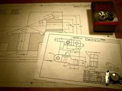
Engineering Connection
For engineers to imagine, create and design the products, devices, and systems that have lasting impact on society, they must know how to present and archive their designs in a manner that is understood by all engineers across cultural and geographical boundaries. To facilitate the sharing of design information, engineers have created uniform standards, protocols, and tools. One of these standards is ANSI Y14.5, which describes how to create a detail drawing. A detail drawing is two-dimensional representation of the engineer's design that contains all the information needed to precisely reproduce it.
Learning Objectives
The objective of this activity is to give students practice drawing 2D sketches of 3D objects using standardized engineering drawing practices.
Educational Standards
Each TeachEngineering lesson or activity is correlated to one or more K-12 science,
technology, engineering or math (STEM) educational standards.
All 100,000+ K-12 STEM standards covered in TeachEngineering are collected, maintained and packaged by the Achievement Standards Network (ASN),
a project of D2L (www.achievementstandards.org).
In the ASN, standards are hierarchically structured: first by source; e.g., by state; within source by type; e.g., science or mathematics;
within type by subtype, then by grade, etc.
Each TeachEngineering lesson or activity is correlated to one or more K-12 science, technology, engineering or math (STEM) educational standards.
All 100,000+ K-12 STEM standards covered in TeachEngineering are collected, maintained and packaged by the Achievement Standards Network (ASN), a project of D2L (www.achievementstandards.org).
In the ASN, standards are hierarchically structured: first by source; e.g., by state; within source by type; e.g., science or mathematics; within type by subtype, then by grade, etc.
Common Core State Standards - Math
-
Identify the shapes of two-dimensional cross-sections of three-dimensional objects, and identify three-dimensional objects generated by rotations of two-dimensional objects.
(Grades
9 -
12)
More Details
Do you agree with this alignment?
-
Visualize relationships between two-dimensional and three-dimensional objects
(Grades
9 -
12)
More Details
Do you agree with this alignment?
International Technology and Engineering Educators Association - Technology
-
Use various approaches to communicate processes and procedures for using, maintaining, and assessing technological products and systems.
(Grades
9 -
12)
More Details
Do you agree with this alignment?
State Standards
Michigan - Math
-
Visualize relationships between two-dimensional and three-dimensional objects
(Grades
9 -
12)
More Details
Do you agree with this alignment?
-
Identify the shapes of two-dimensional cross-sections of three-dimensional objects, and identify three-dimensional objects generated by rotations of two-dimensional objects.
(Grades
9 -
12)
More Details
Do you agree with this alignment?
Oregon - Math
-
Visualize relationships between two-dimensional and three-dimensional objects
(Grades
9 -
12)
More Details
Do you agree with this alignment?
-
Identify the shapes of two-dimensional cross-sections of three-dimensional objects, and identify three-dimensional objects generated by rotations of two-dimensional objects.
(Grades
9 -
12)
More Details
Do you agree with this alignment?
Materials List
Each student needs:
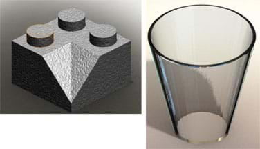
- LEGO brick, corner brick 2 x 2 / 45° inside, Element ID: 4218890 (see Figure 1); order from https://shop.lego.com/en-US/, $1 each; allow at least four weeks for delivery
- 8½ x 11-inch unlined paper (such as blank copier or printer paper)
- pencil
- ruler (metric with mm resolution)
- Hex Cylinder Drawing Handout
For the entire class to share:
- wooden block, with approximate dimensions of 4 x 2 x 1-inch (10 x 5 x 2.5-cm)
- simple-shaped drinking glass, such as one with sloped sides so the top rim diameter is wider than the base diameter (see Figure 1)
- cardboard box; must have a lid, or a top of some sort to conceal the inside of the box, and be large enough to hold a typical drinking glass
- Example Block Detail Drawing
- Example Brick Detail Drawing
- Hex Cylinder 3D Answer
- (optional) computer and (free) eDrawing viewer software from SolidWords (see Additional Multimedia Support and Assessment sections)
Worksheets and Attachments
Visit [www.teachengineering.org/activities/view/cub_detdrawings_lesson01_activity1] to print or download.Pre-Req Knowledge
The associated lesson is a pre-requisite for this activity.
Introduction/Motivation
A "detail drawing" is a drawing of one or more components or parts. Detail drawings have complete and precise descriptions of a part's dimensions, shape and how it is manufactured.
Detail drawings must be concise, in that they convey only the information needed to create the part, such as the size, type of material, finish, tolerance and any special shop instructions. In other words, all information needed to produce the part should be on the detail drawing. The complete standard (agreed-upon rules) for producing detail drawings is controlled by the American National Standards Institute (ANSI) and is titled, "ASME Y14.5 and ASME Y14.100 Dimensioning Tolerancing and Engineering Drawing Practices Package."
Engineers do not typically manufacture their own creative work, but communicate their ideas to highly trained machinists and manufacturers. Engineers also leave a legacy of creative thought through their designs. To preserve this technology, it must be well-documented. A detail drawing is a tool used by engineers to communicate their designs to manufacturers and to preserve their work for future generations.
Procedure
Before the Activity
- At least four weeks before conducting the activity, procure enough of the specific LEGO bricks by placing a special order through Lego.com.
- Gather materials (wooden block, cardboard box, drinking glass, etc.).
- Print out a copy or overhead transparency of the Example Block Detail Drawing, Example Brick Detail Drawing and Hex Cylinder 3D Answer.
- Make copies of the Hex Cylinder Drawing Handout, one per student.
- (optional) Prepare a computer to show an EPRT drawing file.
With the Students
- Conduct the "Mystery Box" pre-activity assessment activity, as described in the Assessment section.
- Review and demonstrate how to picture the seven standard views using third angle projection (see the associated lesson).
- Review pertinent information that should be included on a detail drawing (see the associated lesson).
- Show students the wooden block and tell them the dimensions of each side. Have students create detail drawings of the block. After they have completed their drawings discuss how many views are necessary to fully describe the block. Help them understand that only two views are needed. One of the necessary views is the front view. The other can be any view except the back view, which is identical to the front view (left side, right side, top, or bottom are acceptable). The reason only two views are necessary is that all dimensions are shown with only two views. See the attached Example Block Detail Drawing for a correct drawing of the block.
- Hand out the LEGO bricks and the rulers (one each per student). Have students create detail drawings of the brick. After they have completed their drawings, discuss how many views are necessary to fully describe the brick. Help them understand that four views are needed. Show the attached Example Brick Detail Drawing as the correct drawing of the brick. Have students identify differences between their drawings and the example drawing. Even though the choice of views may be different, a correct drawing has all the information indicated in the example drawing and nothing more. Too much is redundant and missing information is incomplete for someone who needs to make it.
- Ensure that students have created title blocks with the required information in the lower right-hand corners of their pages. Refer to the associated lesson for this information.
- Test students' understanding of communicating via detailed drawings by handing out the Hex Cylinder Drawing Handout, a five-view detail drawing of an arbitrary shape, and giving them time to sketch the 3D object from the 2D drawing. Tell them that the detail drawing of a "hex cylinder" has all the views necessary to reconstruct its three-dimensional shape. See more information in the Assessment section, including an option for showing students the drawing rotated in a software application. Conclude by comparing student sketches to the correct 3D drawing.
Vocabulary/Definitions
ANSI: Acronym for American National Standards Institute.
CAD: Acronym for computer aided design.
CNC: Acronym for computer numeric control.
drawing view: A two-dimensional line drawing of an object as seen from a particular angle. The seven standard views are: front, back, top, bottom, left side, right side, and isometric.
Assessment
Pre-Activity Assessment
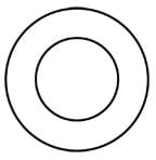
Mystery Box: Before class, place a simple drinking glass (see Figure 1) upright inside a cardboard box, and close the lid. To start the activity, show students the cardboard box and ask them to guess what mystery item might be concealed inside the box. After they make random guesses for a minute, tell them you will give them all the necessary information to know what is in the box, but nothing more. Then, draw Figure 2 on the chalkboard. Explain to students this is what they would see if they could look through the top lid of the box and stare straight down on the mystery object. With these clues, have the students continue to guess what is inside the box.
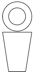
Next, draw another figure on the chalkboard (the drinking glass profile), immediately below the first image, so that your drawing now looks like Figure 3. Explain to the students that this is what they would see if they could look through the front of the box. Tell them that the material of the mystery item is glass. Allow a few more guesses and reveal that it is a drinking glass. Show them the drinking glass and show which of its edges correspond to the sketch edges.
Activity Embedded Assessment
Detail Drawing: Once everyone has finished creating detail drawings of the LEGO brick, display the correct detail drawing by showing the Example Brick Detail Drawing and having students identify differences between their drawings and the example drawing. Note that the choice of views may be different, but regardless, a correct drawing has all the information indicated in the example drawing and nothing more. Too much information is redundant, whereas lack of information insufficient to recreate the part.
Post-Activity Assessment
2D to 3D: Distribute to students the Hex Cylinder Drawing Handout, which is a five-view detail drawing of an arbitrary shape (see Figure 4; don't show students what it looks like yet). Explain that the detail drawing of the "hex cylinder" has all the views necessary to reconstruct its three-dimensional shape. Direct students to look at the given views and sketch the 3D model on a clean sheets of paper (or in lab notebooks). After students have finished, compare drawings and also show them the Hex Cylinder 3D Answer PNG image file, which is a digital rendering of the 3D model. (In addition to showing the PNG image, open the Hex Cylinder 3D Answer EPRT file, which is a 3D model that can be rotated and examined in 3D space in real time. To view the EPRT file, download the free eDrawings viewer from SolidWorks [see Additional Multimedia Support].)

Investigating Questions
Why have standards been created to control drawings made by engineers? (Answer: Standards were created to facilitate communication regarding technical concepts.)
What are examples of a mechanical design that could be difficult to convey in an engineering detail drawing? (Possible answers: An mechanical component with complex surfaces is difficult to fully describe with a detail drawing. Examples: Toys of human figures (like Barbie dolls), automobiles, fighter aircraft, etc.)
How else might design intent be preserved and conveyed if not as a detail drawing? (Possible answers: Digital models using CAD, or scale models.)
A fabrication technique called "rapid prototyping" is often used by engineers. With rapid prototyping, a design goes directly from CAD software to a machine that automatically (or nearly automatically) creates the part. Examples of such machines are computer numeric controlled (CNC) mills, stereo lithographers, laser cutters, etc. Why is it still important to create a detail drawing of a part created by a rapid prototyper, even if the drawing will not be used to manufacture it? (Answer: Detail drawings also contain tolerances, finishes, and other material specifications that are not understood by a rapid prototype machine.)
Activity Scaling
- Sketching and drawing are skills that can be developed early in an engineer's career. Any K-12 grade level student can benefit from this activity with the following possible modifications to make it easier: Disregard the associated lesson and focus on giving students practice sketching real-life objects. Pick (or let the students choose) random classroom objects. Have them sketch objects from a particular viewpoint, then create another sketch of the same object from a different viewpoint (perhaps at 90° from the first viewpoint).
- For younger students (grades 3-5), conduct the The Universal Language of Engineering Drawings activity to practice detailed design drawings through an engineering design challenge. Teams prepare sketches with dimensions and instructions for their model car designs, then trade drawings with other groups and attempt to construct the other teams' models—a test of whether or not the original design intentions were successfully communicated.
Additional Multimedia Support
To view the EPRT file, download SolidWorks' free eDrawings solid model viewer software at: http://www.edrawingsviewer.com/pages/programs/download/
Subscribe
Get the inside scoop on all things Teach Engineering such as new site features, curriculum updates, video releases, and more by signing up for our newsletter!More Curriculum Like This

Students are introduced to detail drawings and the importance of clearly documenting and communicating their designs. They are introduced to the American National Standards Institute (ANSI) Y14.5 standard, which controls how engineers communicate and archive design information.

During this lesson, students discover the journey that a Mars rover embarks upon after being designed by engineers and before being prepared for launch. Students investigate the fabrication techniques, tolerance concepts, assembly and field-testing associated with a Mars exploratory rover.
References
ASME Y14.5 and ASME Y14.100 Dimensioning Tolerancing and Engineering Drawing Practices Package. American National Standards Institute. Accessed May 28, 2011. (The complete standard for producing detail drawings) Available for purchase at: https://webstore.ansi.org/RecordDetail.aspx?sku=ASME+Y14.5+and+ASME+Y14.100+Dimensioning+Tolerancing+and+Engineering+Drawing+Practices+Package&source=package_landing_page
Copyright
© 2010 by Regents of the University of Colorado.Contributors
Benjamin S. Terry, Brandi Briggs, Stephanie Rivale, Denise W. CarlsonSupporting Program
Integrated Teaching and Learning Program, College of Engineering, University of Colorado BoulderAcknowledgements
The contents of these digital library curricula were developed by the Integrated Teaching and Learning Program under National Science Foundation GK-12 grant no. 0338326. However, these contents do not necessarily represent the policies of the National Science Foundation, and you should not assume endorsement by the federal government.
Last modified: September 3, 2021


User Comments & Tips