
Quick Look
Grade Level: 8 (6-8)
Time Required: 1 hour
Expendable Cost/Group: US $0.05 This activity mainly uses non-expendable (reusable) supplies; see the Materials List for details.
Group Size: 2
Activity Dependency: None
Subject Areas: Computer Science, Science and Technology
NGSS Performance Expectations:

| HS-ETS1-2 |
| HS-PS3-2 |
Quick Look
- Grade Level:
- 8 (6 – 8)
- Time Required:
- 1 hour
- Group Size:
- 2
- Subject Areas:
-
Computer Science Science and Technology -
NGSS Performance Expectations:
HS-ETS1-2 HS-PS3-2
 mounted on its top surface. A red wire connects the box to a nearby laptop that has a video game interface on its monitor.")
Summary
What is inside a video game controller? Students learn about simple circuits and switches as they build arcade controllers using a cardboard box and a MaKey MaKey—an electronic tool and toy that enables users to connect everyday objects to computer programs. Each group uses a joystick and two big push button arcade buttons to make the controller. They follow provided schematics to wire, test and use their controllers—exploring the functionality of the controllers by playing simple computer games like Tetris and Pac-Man. Many instructional photos, a cutting diagram and a wiring schematic are included. This activity also introduces students to basic computer science principles. They explore how the MaKey MaKey communicates with a computer via simple algorithms that interpret button presses and joystick movements as inputs.Engineering Connection
Having an understanding of electronics, circuitry, and programming is essential for engineers, especially those involved in software and hardware integration. Electrical engineers design circuits that control devices, while computer engineers write software that interprets user inputs, such as button presses or joystick movements. This combination of electrical systems and programming is fundamental to many technologies, from video games to embedded systems in everyday objects, showcasing how engineers must understand both physical and digital systems to design functional, interactive products.
Learning Objectives
After this activity, students should be able to:
- Identify circuit components and explain their importance.
- Explain the role of engineers in designing video game controllers.
- Assemble a system based on simple circuits.
Educational Standards
Each Teach Engineering lesson or activity is correlated to one or more K-12 science,
technology, engineering or math (STEM) educational standards.
All 100,000+ K-12 STEM standards covered in Teach Engineering are collected, maintained and packaged by the Achievement Standards Network (ASN),
a project of D2L (www.achievementstandards.org).
In the ASN, standards are hierarchically structured: first by source; e.g., by state; within source by type; e.g., science or mathematics;
within type by subtype, then by grade, etc.
Each Teach Engineering lesson or activity is correlated to one or more K-12 science, technology, engineering or math (STEM) educational standards.
All 100,000+ K-12 STEM standards covered in Teach Engineering are collected, maintained and packaged by the Achievement Standards Network (ASN), a project of D2L (www.achievementstandards.org).
In the ASN, standards are hierarchically structured: first by source; e.g., by state; within source by type; e.g., science or mathematics; within type by subtype, then by grade, etc.
NGSS: Next Generation Science Standards - Science
| NGSS Performance Expectation | ||
|---|---|---|
|
HS-ETS1-2. Design a solution to a complex real-world problem by breaking it down into smaller, more manageable problems that can be solved through engineering. (Grades 9 - 12) Do you agree with this alignment? |
||
| Click to view other curriculum aligned to this Performance Expectation | ||
| This activity focuses on the following Three Dimensional Learning aspects of NGSS: | ||
| Science & Engineering Practices | Disciplinary Core Ideas | Crosscutting Concepts |
| Design a solution to a complex real-world problem, based on scientific knowledge, student-generated sources of evidence, prioritized criteria, and tradeoff considerations. Alignment agreement: | Criteria may need to be broken down into simpler ones that can be approached systematically, and decisions about the priority of certain criteria over others (trade-offs) may be needed. Alignment agreement: | |
| NGSS Performance Expectation | ||
|---|---|---|
|
HS-PS3-2. Develop and use models to illustrate that energy at the macroscopic scale can be accounted for as either motions of particles or energy stored in fields. (Grades 9 - 12) Do you agree with this alignment? |
||
| Click to view other curriculum aligned to this Performance Expectation | ||
| This activity focuses on the following Three Dimensional Learning aspects of NGSS: | ||
| Science & Engineering Practices | Disciplinary Core Ideas | Crosscutting Concepts |
| Develop and use a model based on evidence to illustrate the relationships between systems or between components of a system. Alignment agreement: | Energy is a quantitative property of a system that depends on the motion and interactions of matter and radiation within that system. That there is a single quantity called energy is due to the fact that a system's total energy is conserved, even as, within the system, energy is continually transferred from one object to another and between its various possible forms. Alignment agreement: At the macroscopic scale, energy manifests itself in multiple ways, such as in motion, sound, light, and thermal energy.Alignment agreement: These relationships are better understood at the microscopic scale, at which all of the different manifestations of energy can be modeled as a combination of energy associated with the motion of particles and energy associated with the configuration (relative position of the particles). In some cases the relative position energy can be thought of as stored in fields (which mediate interactions between particles). This last concept includes radiation, a phenomenon in which energy stored in fields moves across space.Alignment agreement: | Energy cannot be created or destroyed—it only moves between one place and another place, between objects and/or fields, or between systems. Alignment agreement: |
International Technology and Engineering Educators Association - Technology
-
Follow directions to complete a technological task.
(Grades
3 -
5)
More Details
Do you agree with this alignment?
-
Explain how technology and engineering are closely linked to creativity, which can result in both intended and unintended innovations.
(Grades
6 -
8)
More Details
Do you agree with this alignment?
-
Create an open-loop system that has no feedback path and requires human intervention.
(Grades
6 -
8)
More Details
Do you agree with this alignment?
-
Create a closed-loop system that has a feedback path and requires no human intervention.
(Grades
6 -
8)
More Details
Do you agree with this alignment?
State Standards
Massachusetts - Science
-
Evaluate simple series and parallel circuits to predict changes to voltage, current, or resistance when simple changes are made to a circuit.
(Grades
9 -
10)
More Details
Do you agree with this alignment?
Materials List
Note: The expendable cost for this activity is very low because the main items—MaKey MaKeys, cables, alligator clips, joysticks, arcade buttons, craft knives (~$73 per project/group)—are expensive, yet fully reusable by taking apart the finished products.
Each group needs:
- MaKey MaKey, such as the standard/classic kit for $50 at SparkFun
- USB cable, such as a 6-foot USB mini-B cable for $4 at SparkFun; note that 1 USB cable comes with the above MaKey MaKey kit
- 12 alligator clip wires; such as a 10-pack for $3 from SparkFun; note that 8 alligator clips are included in the above MaKey MaKey kit
- 2 arcade buttons, 1 red, 1 green; such the 35 mm red and green concave momentary push buttons for $2 each at SparkFun
- joystick, such as a short handle arcade joystick for $15 at Sparkfun
- cardboard box; shoebox size is ideal
- X-Acto or craft knife
- strong tape, such as duct tape, packing tape or masking tape
- metal-edged ruler, for cutting and measuring
- pencil or marker
- laptop or computer with USB connection
- Arcade Controller Diagram (same as Figure 1)
- Wiring Schematics Handout
To share with the entire class:
- capability to show students a short video about how to take the buttons apart: Arcade Button Setup
Worksheets and Attachments
Visit [www.teachengineering.org/activities/view/spfun-1851-shoebox-arcade-game-controller-makey-circuit] to print or download.Pre-Req Knowledge
A basic knowledge of circuitry.
Introduction/Motivation
Who has played a video game? What kind of gaming console did you use? Was it handheld and portable or stationary and connected to a monitor like a computer or television? All of these games share a common interface: a controller. A video game controller controls the game effects based on the input we provide.
Think about an “old school” joystick. (Show students a completed controller and demonstrate how a game reacts to your input by manipulating the controller in various directions.) When we move the joystick forward, the video game responds by moving in that direction. Likewise, when we press the buttons, the game reacts according to how the buttons are coded. The controls can be programmed to perform different tasks based on the needs of the game.
Today, we will make our own vintage arcade controllers. First, we will construct and assemble the mechanics of the controller. Then, we will dive into the electrical portion of the procedure. Like electrical engineers, we are going to wire a circuit to enable an electrical flow through the joystick. When we manipulate the controller in a certain direction, a switch (like a gate or a door) opens the “flow” of electricity through the corresponding section of the circuit while the other directions stay closed.
Now, you and your partner are going to build a shoebox arcade controller. When you are done, the controller can be used to play online games. If you want an additional challenge, visit scratch.mit.edu and make your own game. Let’s get started!
Procedure
Background
The circuit components used in this activity are push buttons and a joystick. These components each open and close a circuit to create the desired movement/action in a video game. Pressing a button closes the circuit so electricity can flow freely along that path. When the button is released, the circuit is open, so the path is broken and electricity cannot flow. The joystick works much in the same way as the buttons. Instead of pressing a button directly, the joystick moves in all directions; four button-like components on the bottom of the joystick open when the joystick points in those directions.
Notice the three metal tabs on the small black switch at the bottom of each arcade button. The tab on the bottom of the button is called “ground”; students need to connect an alligator clip wire between the “ground” tab and “earth.” Note: ground and Earth mean the same thing in electronics, sometimes they are also called “-” or negative.
The other two metal tabs on the small black switch are both positive (+) connections. One is hooked to a button pad on the MaKey MaKey (like the “space” pad). The difference between these two tabs is that one is only connected when the button is up (un-pressed) and the other is only connected when the button is down (pressed). Students wire the circuit so that pushing down the button closes the circuit. The Figure 8 wiring schematic shows which tabs to attach the wires to.
Before the Activity
- Gather materials and make copies of Arcade Controller Diagram (same as Figure 1) and Wiring Schematics Handout.
- It is helpful if the teacher builds a controller him/herself prior to guiding the activity.
- Download a simple game such as Tetris in order to visually show how a video game reacts to controller inputs.
With the Students
- Begin by presenting the Introduction/Motivation section. Lead a discussion using the pre-activity assessment questions.
- Organize the class into teams of two students each. Distribute materials to each group.
- Draw the holes to cut: Direct students to draw on the box the location of the joystick and buttons by following the diagram (same as Figure 1). Give students some freedom in the exact placement of the joystick and buttons, but ensure that the holes are the right size (as indicated on the diagram). Point out the four cuts that stick out from the square joystick hole; these cuts are to accommodate the tabs that stick out from the joystick’s buttons.
 and provides dimensions (in blue). A dashed middle line halves the top of the box horizontally to help in placement of a nearly square hole for the joystick (on the left; 2 x 2.7 inches) and two arcade buttons (on the right; two round 1-inch diameter holes)—all placed along the middle line. The joystick’s square cutout also includes four half-inch slots positioned one-quarter-inch away from the edge of each of the rectangle’s sides, sticking out perpendicular to the joystick cutout.")
- Cut the holes: Have students use craft knives to cut the three holes in the box; make the cutouts look like those shown in Figure 2. Provide assistance as necessary. Tips:
- Use a steel ruler to help make straight cuts.
- To cut holes in the cardboard box, use the knife point to poke small cuts through the cardboard around the circle. It’s much easier (and safer) to poke a series of holes around a small circle than to try to drag the knife around the edge of a circle.
- Buttons may be a tight fit into the cut-out circles. If the buttons seem like they won’t fit, advise students to cut around the outside of their drawn circles.

- Mount the joystick onto the box. Tell students: To mount the joystick, slide it through the square hole in the top of your box, making sure that the metal tabs that stick out slide through the short slots cut around the square hole. Since the metal plate on top of the joystick is bigger than the hole, the joystick rests on the top of the box. Use tape to secure the metal plate onto the box.

- Take apart the arcade buttons: Next, students take apart the arcade buttons before using the plastic screw to clamp them onto the tops of their boxes. Tell students: To take apart the buttons, pull back on the plastic clip that holds the small black rectangular switch on the bottom of the button and rotate the small black switch until it comes free. With the switch removed, unscrew the plastic ring (nut) on the bottom of the threaded button shaft (screw). Refer to Figures 3-6 for the process of taking apart the buttons. It may help to show students the short video, Arcade Button Setup, shown below.

 with a black rectangular switch removed from it.")
 tilted slightly to show the thumb moving the black plastic nut (looks like a ring) to unscrew it from the button.")
 and switch (rectangular-shaped with two prongs). Same for the green arcade button.")
- Mount the buttons: Have students mount the arcade buttons to their controllers following these steps.
- Slide the colored body of the button through one of the cardboard holes.
- Inside the box, screw the black plastic screw onto the bottom of the button until it pinches the cardboard and holds the button in place.
- Replace the square black switch on the bottom of the button by rotating it into the plastic clip on the bottom of the button (see Figure 7).


- Wire the buttons: At this point, students have completed the mechanical part of their arcade controller builds! Next, have students starting wiring up their buttons to the MaKey MaKey, according to the wiring handout (same as Figures 8 and 9).
.")

- Wire the joystick: Direct students to examine the joystick and move it around; notice that a metal post swings around and presses four buttons—for up, left, down and right. Referring to the wiring handout again, direct students to wire each of the four joystick buttons to one of the arrow pads on the Makey Makey (also shown in Figure 9).
.")

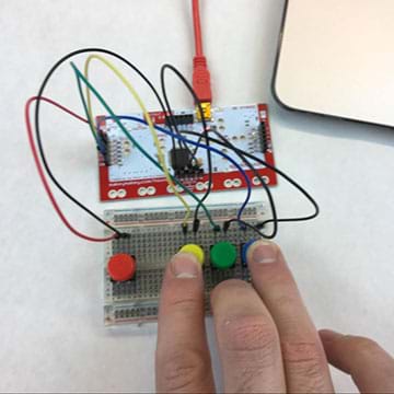
- Testing: Tell students: Once you have the joystick and arcade buttons wired, test all of the buttons using the MaKey MaKey lights. To do this, use a USB cable to plug the MaKey MaKey into a laptop; expect the green lights on the front of the MaKey MaKey to flash for a moment. Then try pressing each button and moving the joystick. What do you see? (Expect students to see a different green light when each button is pressed or when the joystick is moved in each direction.) What happens if you move the joystick diagonally? (That triggers two buttons at the same time.)
- Have students discuss in their groups what input—button pushes, joystick movements—causes what result. Then, discuss as a class. Make sure that the lights work like this:
- Button 1: space
- Button 2: click
- Up on joystick: up arrow
- Left on joystick: left arrow
- Down on joystick: down arrow
- Right on joystick: right arrow

- Use the shoebox arcade controllers: Tell students: Congratulations! You have made your own arcade controller. You can use it to play all kinds of retro arcade games. Search online or specifically at scratch.mit.edu for titles like Super Mario, Pac-Man, Flappy Bird and Tetris, and then use your arcade controller to play the games.
- Give students time to try out a few different games. Then discuss how their arcade controllers work for each one. Refer to the post-activity assessment for guiding questions.
Vocabulary/Definitions
electric current: The flow of electrons in a circuit.
electrical circuit: A path that facilitates electrical flow.
ground: A common return path for current in a circuit. Also called “earth.”
MaKey MaKey: An electronic invention tool and toy that enables users to connect everyday objects to computer programs. Using a circuit board, alligator clips, and a USB cable, the device uses closed loop electrical signals to send the computer a keyboard stroke or mouse click signal. (Source: Wikipedia)
switch: A device that opens or closes the flow of electricity in a circuit.
Assessment
Pre-Activity Assessment
Question/Answer: Ask students the following questions to gauge their understanding of circuits. Write their responses on the board. Discuss their answers as a class. Clarify any misconceptions.
- What is a closed circuit? (Answer: A closed circuit is a circuit with a complete path, which permits charge to flow [current].)
- What would happen if the circuit was not closed (that is, open)? (Answer: An open circuit would not facilitate current flow, and ultimately would prevent the controller from working.)
Activity Embedded Assessment
Design Considerations: While students are wiring their controllers, ask them the following questions:
- Have students disconnect one or two alligator clip wires from the controller. Does the controller work? Why not? (Answer: Disconnecting just one wire can open the circuit, preventing current from flowing through the circuit.)
- On the wiring schematic, can you trace the path that the current takes when you articulate the joystick forward?
Post-Activity Assessment
Controller Use: Have students download simple video games that utilize clear up, down, left, and right controls, such as Tetris. Suggest that students find games by searching for “tetris” or “pac-man” at scatrach.mit.edu. In a discussion format, ask students the following questions to gauge their depth of comprehension:
- How might you wire the joystick and MaKey MaKey to reverse the directions on the controller? (Answer: Switch the wiring on the MaKey MaKey; “up” joystick button to “down” MaKey MaKey pad and “down” joystick button to “up” MaKey MaKey pad. Or, switch the joystick wiring.)
- How might you wire the buttons and MaKey MaKey so that the first button performed the “click” task and the second button performed the “space” task? (Answer: Switch the wires connected to the buttons or switch the wiring on the MaKey MaKey pad.)
Safety Issues
Never force the X-Acto knife if it gets stuck. Instead, use the point to make several cuts along the same line until the knife cuts through and along your line without so much force.
Troubleshooting Tips
Alligator clips need to be tiny. The alligator clips that come with the MaKey MaKey kit and those listed/linked in the Materials List are the appropriate size.
If the joystick or a button seems to be pressed when no one is touching it, the circuit may be closed due to touching alligator clips. Ensure that the rubber covers completely cover the clips to prevent accidental circuit mishaps and short circuits.
Activity Extensions
Use Scratch to make your own game. Go to scratch.mit.edu to learn more.
Additional Multimedia Support
Watch a fun two-minute introduction to MaKey MaKey at https://www.youtube.com/watch?v=rfQqh7iCcOU.
As needed, show students a short (50-second) video, Arcade Button Setup.
Subscribe
Get the inside scoop on all things Teach Engineering such as new site features, curriculum updates, video releases, and more by signing up for our newsletter!More Curriculum Like This

Students wire up digital trumpets using a MaKey MaKey, learning breadboard wiring basics and using the digital trumpets to count in the binary number system. Teams play songs in a class concert.
Students explore the composition and practical application of parallel circuitry, compared to series circuitry. Students design and build parallel circuits and investigate their characteristics, and apply Ohm's law.

References
Activity adapted from SparkFun’s Shoebox Arcade Controller activity at https://invent.sparkfun.com/cwists/preview/1500x
Copyright
© 2017 by Regents of the University of Colorado; original © 2016 SparkFun EducationContributors
Angela Sheehan; Morgan UlrichSupporting Program
SparkFun EducationLast modified: November 12, 2024
User Comments & Tips