Quick Look
Grade Level: 10 (9-12)
Time Required: 1 hours 30 minutes
(can be split into two sessions)
Expendable Cost/Group: US $0.00 This activity uses some non-expendable materials; see the Materials List for details.
Group Size: 2
Activity Dependency: None
Subject Areas: Computer Science, Science and Technology
Summary
Students create projects that introduce them to Arduino—a small device that can be easily programmed to control and monitor a variety of external devices like LEDs and sensors. First they learn a few simple programming structures and commands to blink LEDs. Then they are given three challenges—to modify an LED blinking rate until it cannot be seen, to replicate a heartbeat pattern and to send Morse code messages. This activity prepares students to create more involved multiple-LED patterns in the Part 2 companion activity.Engineering Connection
In the 21st century, acquiring the basics of programming and computer science, as well as a basic comfort level with electromechanical devices, are foundational knowledge for all engineers, and required components of engineering education. In these projects, students apply an understanding of sequence and control to create a variety of specified LED blinking patterns.
Learning Objectives
After this activity, students should be able to:
- Blink an LED on an Arduino at a given rate.
- Create a specific blinking pattern such as mimicking a heartbeat or representing a message encoded in Morse code.
Educational Standards
Each TeachEngineering lesson or activity is correlated to one or more K-12 science,
technology, engineering or math (STEM) educational standards.
All 100,000+ K-12 STEM standards covered in TeachEngineering are collected, maintained and packaged by the Achievement Standards Network (ASN),
a project of D2L (www.achievementstandards.org).
In the ASN, standards are hierarchically structured: first by source; e.g., by state; within source by type; e.g., science or mathematics;
within type by subtype, then by grade, etc.
Each TeachEngineering lesson or activity is correlated to one or more K-12 science, technology, engineering or math (STEM) educational standards.
All 100,000+ K-12 STEM standards covered in TeachEngineering are collected, maintained and packaged by the Achievement Standards Network (ASN), a project of D2L (www.achievementstandards.org).
In the ASN, standards are hierarchically structured: first by source; e.g., by state; within source by type; e.g., science or mathematics; within type by subtype, then by grade, etc.
Common Core State Standards - Math
-
Interpret functions that arise in applications in terms of the context
(Grades
9 -
12)
More Details
Do you agree with this alignment?
International Technology and Engineering Educators Association - Technology
-
Students will develop an understanding of the characteristics and scope of technology.
(Grades
K -
12)
More Details
Do you agree with this alignment?
-
Students will develop an understanding of the attributes of design.
(Grades
K -
12)
More Details
Do you agree with this alignment?
Materials List
Each group needs:
- Arduino Uno microcontroller board, such as the SparkFun RedBoard (see Figure 1) for $20 at https://www.sparkfun.com/products/12757
- USB cable for connecting the Arduino board to a computer; such as this USB mini-B 6-foot cable for $4 at https://www.sparkfun.com/products/11301
- 1 LED (see Figure 1); such as this basic red 5-mm LED for 35¢ at https://www.sparkfun.com/products/9590 or 20-packs at https://www.sparkfun.com/products/12062; if planning to complete the companion activity, Build Your Own Arduino Light Sculpture! Part 2, it is recommended that you purchase the packs
- computer with Arduino IDE (free to download) and FTDI drivers
Introduction/Motivation
Using a programmable microcontroller, let’s see how you can combine color, shape, form and space to create your own works of art!
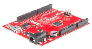
At the heart of this project is the Arduino Uno (or the SparkFun RedBoard; shown in Figure 1; hold up the circuit board to show the class). This small device can be easily programmed to control and monitor a variety of external devices like LEDs and sensors to accomplish a wide range of purposes. Let’s get started!
Procedure
Background
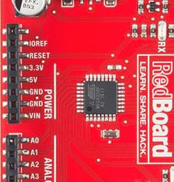
Pins: Look closely at the Arduino board; notice a small black square chip near the center of the board (see Figure 2). Tilt the board and notice lines, or what are called traces, connecting this chip to the sides of the board. These are called pins.
An Arduino has two main types of pins: power pins and GPIO pins (see Figure 2). Power pins are used to supply power to the board as well as supply power to any external circuits you build; these are labeled 5V, 3.3V, GND and Vin. All of the other pins are general purpose input\output (GPIO) pins. As the name indicates, these pins can be used as either inputs or outputs.
Let’s get coding! Arduino is an open-source hardware and software platform developed in 2005. We’ll be using Arduino software [IDE]. Programs written using IDE are called sketches. These sketches are written in the text editor and are saved with the file extension, ino.
Comments: Programmers use comments to leave notes about what’s going on. Arduino ignores comments. You can write comments in two ways. A single-line comment is any text that has two forward slashes, //, in front of it. Sometimes programmers have multiple lines of text that are comments; these are surrounded by the following two character pair: /* and */.
Program Flow and Control: Every Arduino sketch must have a minimum of two functions: setup() and loop(). The setup() function runs once at the beginning, and the loop() repeats over and over at a rate of about a million times per second! Because it runs so fast, we often use the delay([time_ms]) function to slow things down. This function pauses the program for a certain number of milliseconds before executing the next line of code.
Input vs. Output: All of the pins on the Arduino (20 total) are generic. Before we use a pin as an output to drive current to an LED, we must configure Arduino using the pinMode([pin], OUTPUT) command where [pin] is the identifying number of the pin on the Arduino.
Digital vs. Analog: The term “digital” means that an object can have two states. In the case of a digital pin, the state can be either high or low. We set this by using the digitalWrite([pin], [HIGH/LOW]) command.
Before the Activity
Gather materials and prepare the computers for student pairs. As necessary, refer to “How to Install FTDI Drivers” at https://learn.sparkfun.com/tutorials/how-to-install-ftdi-drivers.
With the Students
Divide the class into groups of two students each. Then direct the groups to each complete the following procedure:
- Test the Device: After any necessary drivers are installed, use a USB cable to connect your Arduino Uno device (such as the SparkFun RedBoard) to your computer. Wait for the drivers to initialize, and then select the appropriate port. Mac users will see something resembling /dev/tty.usbserial. Windows users will see a COM#. Select the one pertaining to the device you just plugged in and then click Run on Arduino. If all is well, you will see the LED labeled 13 blink (on for one second and off for one second).
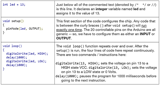
- Play with the Code: Click on the Give it a try! button to see the code and play around (see Figure 3). Note: Two functions are required in every Arduino sketch: void setup() and void loop() (see Table 1). A function is a way to group several instructions together. The instructions are grouped together using two curly brackets (aka braces) { }.
- Adding an LED: While the little blue LED on the board is fun, let’s see if we can learn a little about how circuits work and wire an LED circuit onto our board.
- We mentioned that the pins on the Arduino are for hooking up inputs and outputs to the microcontroller. We can use an LED to simply demonstrate that fact.
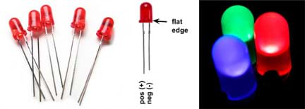
- Grab an LED and look closely at it (see Figure 4). Notice that one wire leg is shorter than the other; the shorter one is the LED’s negative or cathode leg. Always make sure this leg is connected and pointed in the direction of ground (GND)—also known as the negative side of the power circuit.
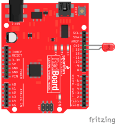
- Now, simply stick the LED directly into the pin 13 and GND headers on the right side of the board, making sure that the shorter leg is connected to GND, as in Figure 5.
- Challenge 1: Flash! Modify the code example so that the LED blinks at a rate of 100 times per second. What do you see? Is the LED still blinking? Adjust the blink rate until you can just barely see it blinking. What is time period for the blink? How would you describe the frequency or rate of this blink? (Teacher points to make: Frequency is defined as 1/T where T is the total time period of the cycle. T is the sum of the two delays, the first one being how long the LED is on and the second being how long the LED is off. Frequency is measured in units called hertz or 1/second. As an example, if students set the delay to 10 ms ON and 10 ms OFF, the total period is 20 ms, which is equal to a frequency of 50 hz or 50 times per second. While it varies per person, at this rate, most people will no longer be able to see the LED blink. But by physically moving the board back and forth, students can see the LED “paint dots” in the air, and they’ll see the blinking. This phenomena is known as persistence of vision (POV) and is related to the refresh rate of the human eye. Students may have seen “internet message clocks” for sale that use this technology—moving a row of flashing LEDs back and forth to display patterns—so that the time or incoming messages appear to be floating in mid-air.)
- Challenge 2: Sweet Heart: Now, adjust the sequence and timing of the on (high) and off (low) cycle to replicate a heartbeat pattern. Hint: A heartbeat has two distinct beats.
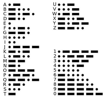
- Challenge 3: Morse Code: Morse code is a method for transmitting text using a sequence of short (dot) and long (dash) beeps, blips or flashes. With the invention of the electric telegraph system in the early 1830s, Morse code was used to transmit text across long distances.
Encode a short word, your name or a message. See if you can communicate a message across the room to another student. In emergencies, the code SOS is internationally recognized as a distress signal. Hint: It helps to leave noticeable pauses between letters and words.
Vocabulary/Definitions
Arduino: A general term used to describe a type of open-source microcontroller board and programming language/environment.
circuit: A complete electrical loop that connects a power source, through a device, and back to the power source.
compile: Converting human-readable code into 1s and 0s that instruct a microcontroller how to behave and perform.
digital: Refers to values that exist in only one of two states. Generally this is “on” or “off.”
ground: The return for current flow in a circuit. Ground refers to the negative terminal of the power supply on the Arduino. Abbreviated as GND.
light-emitting diode: A device that converts electrical energy into light energy. LEDs are polarized; they only work when they are connected in the correct direction. The long leg of a standard LED is usually the positive side. LEDs have very low resistance. LEDs have a maximum current of about 20 mA.
microcontroller: A small computer on a single integrated circuit (chip) containing a processor core, memory and programmable input/output peripherals. It is the “brain” of the system. Sometimes abbreviated µC, uC or MCU (microcontroller unit).
pin: A physical connection on the outside of a microcontroller. Pins are general purpose and can be either inputs or outputs to the microcontroller.
upload: Sending the program to the microcontroller.
Assessment
Pre-Activity Assessment
Warm-Up Task: Ask students to each write a simple program in Arduino that repeatedly turns an LED on for one second and then off for one second—to check their understanding of basic Arduino coding.
Activity Embedded Assessment
Discovery: During the activity, ask students to see what happens when they remove the pinMode() command. Demonstrate a simple way to “remove” code by making it into a comment using two forward slashes //.
Post-Activity Assessment
Exit Ticket: At activity end, ask students the following questions:
- Describe the difference between the setup() and the loop() parts of the code. (Answer: Both setup() and loop() are known as functions. The setup() part of the code runs just once at the beginning when the Arduino starts up, and the loop() part of the code repeats over and over.)
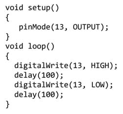
- Write a short sketch (program) that blinks continuously at a rate of five blinks per second. (Answer: The frequency of the blink is 5 blinks per second, so f = 5 Hz. This means that the total time, T, needs to be T=1/f or T = 1 / 5, which is 0.200 seconds. Figure 7 shows a quick example sketch that works. As long as the total time delay adds up to 0.200 seconds or 200 ms, this will work. Other examples may include a delay of 190 and 10 or 150 and 50. So long as the sum of the two delay times is equal to 200 ms.)
Safety Issues
Make sure that students do not plug the LED directly between 5V and GND without a current limiting resistor, or else the LED will burn out and may even pop and crack the LED’s plastic lens.
Troubleshooting Tips
- Make sure the board is plugged in.
- Double check that the board setting and the port settings are set appropriately.
Activity Extensions
Continue the fun by having students complete the second part of this activity, Build Your Own Arduino Light Sculpture! Part 2.
Subscribe
Get the inside scoop on all things Teach Engineering such as new site features, curriculum updates, video releases, and more by signing up for our newsletter!More Curriculum Like This

Students learn how to connect Arduino microcontroller boards to computers and write basic code to blink LEDs. Provided steps guide students through the connection process, troubleshooting common pitfalls and writing their first Arduino programs. Then they independently write their own code to blink ...

In the companion activity, students experimented with Arduino programming to blink a single LED. During this activity, students build on that experience as they learn about breadboards and how to hook up multiple LEDs and control them individually so that they can complete a variety of challenges to...

Students gain practice in Arduino fundamentals as they design their own small-sized prototype light sculptures to light up a hypothetical courtyard. They program Arduino microcontrollers to control the lighting behavior of at least three light-emitting diodes (LEDs) to create imaginative light displ...

Students write Arduino code and use a “digital sandbox” to create new colors out of the three programming primary colors: green, red and blue. They develop their own functions, use them to make disco light shows, and vary the pattern and colors of their shows.
Copyright
© 2016 by Regents of the University of Colorado; original © 2014 SparkFun EducationContributors
Brian HuangSupporting Program
SparkFun EducationLast modified: August 17, 2018


User Comments & Tips