
Quick Look
Grade Level: 10 (9-12)
Time Required: 1 hours 30 minutes
(can be split into two sessions)
Expendable Cost/Group: US $0.00 The activity uses some non-expendable materials; see the Materials List for details.
Group Size: 2
Activity Dependency:
Subject Areas: Computer Science, Science and Technology

Summary
In the companion activity, students experimented with Arduino programming to blink a single LED. During this activity, students build on that experience as they learn about breadboards and how to hook up multiple LEDs and control them individually so that they can complete a variety of challenges to create fun patterns! To conclude, students apply the knowledge they have gained to create LED-based light sculptures.Engineering Connection
In the 21st century, acquiring the basics of programming and computer science, as well as a basic comfort level with electromechanical devices, are foundational knowledge for all engineers, and required components of engineering education. During these projects, students apply an understanding of sequence and control to create a variety of LED blinking patterns.
Learning Objectives
After this activity, students should be able to:
- Control multiple outputs (LEDs) and sequence patterns using code.
- Describe how a solderless breadboard is used for rapid prototyping of circuits.
Educational Standards
Each Teach Engineering lesson or activity is correlated to one or more K-12 science,
technology, engineering or math (STEM) educational standards.
All 100,000+ K-12 STEM standards covered in Teach Engineering are collected, maintained and packaged by the Achievement Standards Network (ASN),
a project of D2L (www.achievementstandards.org).
In the ASN, standards are hierarchically structured: first by source; e.g., by state; within source by type; e.g., science or mathematics;
within type by subtype, then by grade, etc.
Each Teach Engineering lesson or activity is correlated to one or more K-12 science, technology, engineering or math (STEM) educational standards.
All 100,000+ K-12 STEM standards covered in Teach Engineering are collected, maintained and packaged by the Achievement Standards Network (ASN), a project of D2L (www.achievementstandards.org).
In the ASN, standards are hierarchically structured: first by source; e.g., by state; within source by type; e.g., science or mathematics; within type by subtype, then by grade, etc.
Common Core State Standards - Math
-
Interpret functions that arise in applications in terms of the context
(Grades
9 -
12)
More Details
Do you agree with this alignment?
International Technology and Engineering Educators Association - Technology
-
Students will develop an understanding of the characteristics and scope of technology.
(Grades
K -
12)
More Details
Do you agree with this alignment?
-
Students will develop an understanding of the attributes of design.
(Grades
K -
12)
More Details
Do you agree with this alignment?
Materials List
Each group needs:
- Arduino Uno microcontroller board, such as the SparkFun RedBoard for $20 at https://www.sparkfun.com/products/12757
- USB cable for connecting the Arduino board to a computer; such as this USB mini-B 6-foot cable for $4 at https://www.sparkfun.com/products/11301
- solderless breadboard, such as this one for $5 at https://www.sparkfun.com/products/12002
- 4 (or more) LEDs; up to 20 per team; such as this assorted color 20-pack for $3 at https://www.sparkfun.com/products/12062
- 4 (or more) 330-ohm resistors
- 4 (or more) short jumper wires
- computer with Arduino IDE (free to download) and FTDI drivers
- Student Wiring Diagram Handout

Worksheets and Attachments
Visit [www.teachengineering.org/activities/view/spfun_lightsculpt_activity2] to print or download.Pre-Req Knowledge
Students should have completed the companion activity, Build Your Own Arduino Light Sculpture! Part 1. Additionally, students should be familiar with parallel and series circuits.
Introduction/Motivation
LEDs are everywhere! They are wonderful and amazing semiconductor devices that emit light without heating a filament or a gas. They are a very cool engineering invention that use the properties of elements, electrons and something called band gaps. LEDs come in a variety of colors and are very small. In the last activity, we learned that one leg of the LED is longer than the other. Do you remember which side is positive and which side is negative? That’s right, the shorter lead is the LED’s negative or cathode leg.
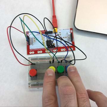
In our last activity (Build Your Own Arduino Light Sculpture! Part 1), we simply built our circuits right on top of the Arduino boards. That was kind of a short-cut. Doing it that way does not give us many options for adding any more LEDs. In order to do that, we need to use solderless breadboards to build our circuits (shown in Figure 1; hold up a breadboard to show the class or pass around a few for students to examine).

Let’s take a closer look at the breadboard. Do you see the repeating rows of five holes? Each row of five holes are connected internally by a metal clip. So, rather than twisting wires together or soldering them, we can simply plug wires into the same row to connect them together!
Notice the two columns on the right and left sides of the breadboard. These are called power rails. These holes are connected vertically, which enables us to connect many devices to the power and ground pins of our circuit.
If connected side-by-side or in a parallel circuit on the Arduino, multiple LEDs can be controlled by a single pin. A parallel circuit is when two elements share the same two connection points to the circuit. Series circuits, on the other hand, are when two elements are wired up sequentially, one after another.
Procedure
Before the Activity
- Gather materials and make copies of the Student Wiring Diagram Handout.
- Prepare the computers for student pairs. As necessary, refer to “How to Install FTDI Drivers” at https://learn.sparkfun.com/tutorials/how-to-install-ftdi-drivers.
With the Students: Wiring and Coding
- Divide the class into groups of two students each.
- Have students refer to the wiring diagram handout (same as Figure 2) to guide them through the wiring. Make sure that if they intend to connect two wires that they insert the wires in the same row. Have each student group complete the following:
- Start by first running a wire from the GND pin on the Arduino to the (-) power rail on the left side of the breadboard. Doing this ensures that anything further that is plugged into the (-) power rail will also be connected to GND.
- Add four LEDs, starting from the top. Remember that each LED has a long leg and a short leg. Plug the longer leg into the first row and the shorter leg into the second row.
- Next, use a 330-ohm resistor to connect the second row (and the short leg of the LED) to GND.
- Finally, connect pin 13 to the long leg of the LED using a short jumper wire to the first row. Repeat this for the remaining three LEDs.
 connected to a solderless breadboard with four LED lights wired in. The wiring diagram shows the placement of the four LEDs each in a pin (13, 12, 11, 10), which are, in turn, each connected through a 330-ohm resistor to the GND.")
- Have students create a new sketch and modify it so that it looks like the code shown in Figure 3. This is a quick and simple code example to get all four LEDs blinking. Expect this code to look familiar to the first example; in this case, we have just added code to control the other three pins. (Remember: The code uses special punctuation marks and is case-sensitive.)
 and void loop() commands, as well as pinMode, digitalWrite and delay. The comments say: Set the LED pins to HIGH. Turn LEDs on! Wait for ½ a second. Set the LED pins to LOW. This turns them off. Wait for ½ a second.")
- Have students upload the code by clicking Run on Arduino. If any syntax errors appear, suggest that students double-check their typing. Once students get a message that says “Done uploading,” have them take a look at their circuits—all four LEDs should be blinking!
- Review with students what the code is doing by explaining each section of the code (see Figure 4).
 will run exactly one time. Since all of the pins are GPIOs, we need to define how the pin is going to be used. We define these each to be OUTPUTs and we do this with the pinMode([pin,OUTPUT); command inside the setup() part of the code. For example: The void loop() function repeats over and over. After the setup() is run, the four lines of code here repeat continuously. There are two commands / instructions here: etc.")
With the Students: Challenges
- LED Chaser: Modify the code so that the LEDs turn on one at a time, one after another from left to right, with at least 1/10 of a second before the next LED turns on, and then all turn off. Bonus: Now, modify it so that the LEDs also turn off one at a time.
- Ping Pong: Modify the code so that just one LED turns on and moves from left to right and then back—so it looks like the LED is bouncing back and forth. Bonus: Now modify the code so that it speeds up and slows down gradually.
- Mo’ LEDs: Modify the code to create a sequence of eight or more LEDs. Hint: Remember to add a pinMode() in the setup() for each new pin you use!
- Cylon / Knight Rider / Larson Scanner: Don’t know what these patterns are? Research them and replicate these patterns using your LEDs and your coding skills.
- Maker’s Choice: Design your own pattern and then code it up. Plan out a sequence of LEDs that does something unique. Perhaps choreograph blinking LED to 15 seconds of music. Make a video recording to capture your creation. Teacher note: For this challenge, encourage students to spend time designing and not just randomly throwing things together. Suggest that they draw, explain and/or jot down their design ideas on paper before writing any code.
- Grand Challenge—Light Sculpture: Have students create light sculptures using glue sticks, plastic cups, construction paper or any other found materials. Challenge students to think about how they might re-position the LEDs and modify their code to create a cool effect. Use extension wires to move the LEDs from the breadboard. After students construct their sculptures, direct them back to programming them. Suggest that they create a minimum of two different “modes” or programs that run on their sculptures with a two- or three-second “off” period between the two modes. For example, make the first mode a simple, soft, slow changing pattern, and the second a disco/dance party light.
Vocabulary/Definitions
circuit: A complete electrical loop that connects a power source, through a device, and back to the power source.
parallel circuit: Two elements that share the same two connection points to the circuit. A circuit that has two (or more) branches for separate currents from one voltage source.
series circuit: A circuit composed solely of components connected in series, meaning they are wired up sequentially, one after another.
solderless breadboard: A device that consists of metal clips that enable a maker to quickly connect wires together without solder or twisting wires together. The metal clips are hidden beneath a plastic case that is divided into groups of five holes. Each row of five holes are connected electrically by the metal clip. Some breadboards have power rails on the sides. These “rails” are like a power strip and are connected vertically; one column is for power (5V) connections and another is for ground (-) connections.
Assessment
Pre-Activity Assessment
Warm-Up Task: Ask students to each sketch a simple circuit using two LEDs in parallel—to check their understanding of the concept.
Activity Embedded Assessment
Tasks: Use a check-sheet to mark when students have completed the challenge tasks. Left-to-right chaser, ping-pong, sequence of eight or more, cylon/Knight rider/Larson scanner, maker’s choice, and light sculpture.
Post-Activity Assessment
Exit Ticket: At activity end, ask students: What is the difference between a parallel and a series circuit?
Safety Issues
Make sure that students do not plug the LED directly between 5V and GND without a current limiting resistor, or else the LED will burn out and may even pop and crack its plastic lens.
Troubleshooting Tips
- Make sure the board is plugged in.
- Double check that the board setting and the port settings are set appropriately.
Subscribe
Get the inside scoop on all things Teach Engineering such as new site features, curriculum updates, video releases, and more by signing up for our newsletter!More Curriculum Like This

Students wire up digital trumpets using a MaKey MaKey, learning breadboard wiring basics and using the digital trumpets to count in the binary number system. Teams play songs in a class concert.
Copyright
© 2016 by Regents of the University of Colorado; original © 2014 SparkFun ElectronicsContributors
Brian HuangSupporting Program
SparkFun EducationLast modified: August 17, 2018
User Comments & Tips