Quick Look
Grade Level: 6 (5-7)
Time Required: 15 minutes
Lesson Dependency: None
Subject Areas: Physical Science

Summary
Students learn about the underlying engineering principals in the inner workings of a simple household object – the faucet. Students use the basic concepts of simple machines, force and fluid flow to describe the path of water through a simple faucet. Lastly, they translate this knowledge into thinking about how different designs of faucets also use these same concepts.Engineering Connection
Engineers use the principles of mechanical systems and fluid systems to design many everyday objects, such as the faucet. Engineers use mathematical equations to figure out the associated pressure, force and flow of a fluid in such objects. Another good example of engineering, mechanical and fluid systems used together is a dam and the gates of the dam that hold the water back. As the gates open, the water starts to drain out from the associated reservoir. To prevent disaster, the water pressure on the gate has to be directly proportional to the area of the water that is flowing past the gate. Engineers must know how everything relates in order for all systems to work together.
Learning Objectives
After this lesson, students should be able to:
- List two engineering concepts used in designing a faucet: simple machines and fluid flow.
- Describe at least one simple machine used in a basic faucet.
- Describe the flow of water in a faucet.
Educational Standards
Each TeachEngineering lesson or activity is correlated to one or more K-12 science,
technology, engineering or math (STEM) educational standards.
All 100,000+ K-12 STEM standards covered in TeachEngineering are collected, maintained and packaged by the Achievement Standards Network (ASN),
a project of D2L (www.achievementstandards.org).
In the ASN, standards are hierarchically structured: first by source; e.g., by state; within source by type; e.g., science or mathematics;
within type by subtype, then by grade, etc.
Each TeachEngineering lesson or activity is correlated to one or more K-12 science, technology, engineering or math (STEM) educational standards.
All 100,000+ K-12 STEM standards covered in TeachEngineering are collected, maintained and packaged by the Achievement Standards Network (ASN), a project of D2L (www.achievementstandards.org).
In the ASN, standards are hierarchically structured: first by source; e.g., by state; within source by type; e.g., science or mathematics; within type by subtype, then by grade, etc.
Common Core State Standards - Math
-
Fluently divide multi-digit numbers using the standard algorithm.
(Grade
6)
More Details
Do you agree with this alignment?
-
Fluently add, subtract, multiply, and divide multi-digit decimals using the standard algorithm for each operation.
(Grade
6)
More Details
Do you agree with this alignment?
-
Write, read, and evaluate expressions in which letters stand for numbers.
(Grade
6)
More Details
Do you agree with this alignment?
International Technology and Engineering Educators Association - Technology
-
Explain how knowledge gained from other content areas affects the development of technological products and systems.
(Grades
6 -
8)
More Details
Do you agree with this alignment?
State Standards
Colorado - Math
-
Add, subtract, multiply, and divide decimals to hundredths.
(Grade
5)
More Details
Do you agree with this alignment?
Worksheets and Attachments
Visit [www.teachengineering.org/lessons/view/cub_faucets_lesson01] to print or download.Pre-Req Knowledge
Students should have some basic knowledge of simple machines and be able to understand the concept of pressure.
Introduction/Motivation
There is so much cool engineering in our houses. Today, we are going to learn about a common object that everyone comes in contact with often. We are going to learn about faucets.
Think about all the different kinds of faucets you have seen. There are faucets that you screw a knob to turn on; there are faucets that you pull a lever to turn on; there are faucets that you push a button to turn on and there are some faucets that you do not even have to touch to turn on. At some point, an engineer had to design all of these faucets.
Several important engineering concepts are used in each and every faucet. The first one is simple machines. Most faucets use a common simple machine such as a screw or a lever in order to produce the force necessary to stop water from continuously flowing. Another engineering concept that a faucet uses is fluid flow. Faucets must hold back water flow when turned off, and regulate water flow when turned on. For our lesson today, we will focus on a common faucet with just one knob, similar to an outdoor faucet to which you might attach a garden hose.
We will start with the water and work our way from the pipes in your house, through the faucet, and out into your sink. Water in the pipes in your house is held at a pressure higher then the pressure of the air around you. This pressure difference is what causes the water to come up from the ground-level pipes coming into your house, and out through the faucet. If, for some reason, the pressure of the air around you rose to that of the water pressure in the pipe, the water would no longer flow out of the pipe. So, due to the pressure in the pipe, the water is ready for motion. All a faucet has to do is hold the water back until we want to use it.
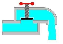
If you were a water molecule flowing through this faucet, the first thing you would come in contact with is a small circular opening: about a quarter of an inch in diameter. On the other side of this opening would be a small rubber stopper. If the faucet were off, that stopper would be pressed up against the opening from the other side. This is what holds the water back. The rubber stopper is held in place by a simple machine, the screw. Who knows to which simple machine the screw is related? The wedge. A screw is a wedge wrapped around a cylinder.
Now let's add some fluid flow. As the faucet is turned on, the screw makes the rubber stopper back away from the opening, creating a small crack through which you — the water molecule — and a few thousand of your friends can pass. The pressure inside the pipe drops as you go through the opening. Remember, without this pressure drop, you would not be able to go through the opening. When the faucet is turned off, the screw works in the other direction and closes the opening, stopping the water flow — thus prohibiting you from passing through the opening.
That is basically how the water gets from the pipes in the ground, through the faucet in your house, and out into your sink. Remember, engineers design simple faucets with two important engineering concepts in mind – simple machines and fluid (water) flow. Following the lesson, conduct the associated activity Too Much Pressure! Modeling Force-Pressure-Area Relationships to help illustrate the relationsip betwen force, pressure and area, by creating a simple system that holds back water from pipes of varying diameters.
Lesson Background and Concepts for Teachers
The Role of Pressure
Water in the pipes in our house is held at a pressure higher than the pressure of the air around us. This pressure difference is what causes water to come up through ground-level pipes, into your house, and eventually spill out of the faucet. Usually, that pressure is created due to the hydrostatic pressure gradient. The best way to think of hydrostatic pressure is to think about swimming pools. When you dive deep under water in a swimming pool, you ears usually hurt — this is because of the increase in pressure. The deeper you go, the more pressure there is and the more your ears hurt. This holds true so long as the water is not moving much — which is where the "static" part comes into play. In fact, the relationship between pressure and depth is accurately modeled by the following equation:
P = ρgh
where P is the pressure, ρ is the density of the liquid (water), g is gravity, and h is the height of water above the point in question.
Sample Calculation: Water has a density of 999 kilograms per cubic meter; gravity on Earth is about 9.81 meters per second squared. If a cylinder of water if filled five meters high, the pressure can be calculated by:
999 kg/m3 × 9.81 m/s2 × 5 m = 49.0 kPa.
So the pressure is 49 kilopascals, which is equal to 1000 Newtons per square meter. Therefore, it is important to know that pressure can be measured in kilopascals or newtons.
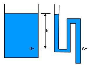
One can find the pressure of a fluid at any given point, knowing no more than the density of fluid, gravity, and the height up to the top of the water. So, because the density of water and gravity are always equal, pressure is really just dependant on height. Therefore, as illustrated in Figure 1, point A and B are at the same height, h, and so the pressure starts out equal at both points.

However, the pressure drops as the water goes through the narrow opening (in the vessel on the right of Figure 1). Without this pressure drop, the water would not go through the opening. And because the hole is rather small, it offers resistance to the flow. The rate that water goes through the faucet, then, is equal to the difference in pressure divided by the resistance of the opening, or:
PInside - POutside = (Rate of Flow)*(Resistance)
You can see, in the above equation, that if the pressure outside equals the pressure inside, then the left side of the equation must equal zero. Thus, either the rate of flow or the resistance must be equal to zero. We can conclude that the rate of flow must equal zero, since all pipes have at least some small amount of resistance. Additionally, if the pressure difference becomes very large, and the resistance is relatively small, the rate of flow will become rather large. Finally, if the pressure difference stays the same, but the resistance drops, the rate of flow will increase. This resistance drop is exactly what happens when the faucet is opened, and the rubber stopper is moved away from the opening.
How Much Force?
So how much force does it take to hold back all that water? Luckily, it is easy enough to calculate: the force needed is equal to the pressure of the water multiplied by the area of the opening. This is expressed by the common equation:
F=P*A
Where F is the force of the water on the stopper, P is the pressure of the water, and A is the area of the opening. Because the stopper is not moving, the force of the water on the stopper must equal the force of the stopper on the water.

Sample Calculation: Let's say that the water in the pipe (shown in Figure 2) is at about 30 psi (pounds per square inch; this will become important later). Secondly, the area of the opening is 0.049 square inches (obtained by taking the radius of the opening squared, multiplied by pi). So the force of the water on the rubber stopper is equal to 30 psi multiplied by 0.049 square inches or:
(30 psi)*(0.049 in^2) = 1.47 lb
We know that the answer should be some unit of force. Pounds per square inch multiplied by square inches is indeed equal to pounds, so the units work out.
How is a Faucet a Machine?
Now let's move on to the mechanical system in the common faucet. The rubber stopper is moved into place by a screw (see Figure 2). This screw serves to reduce the force needed to hold back the water. A screw converts a torque (a twisting force) into a linear force. It also provides mechanical advantage that converts a small input force into a potentially large output force. To illustrate the concept of mechanical advantage, we can look at an example of a simple wedge lifting a box in Figure 3.

Sample Calculation: Let's say that the box in Figure 3 weighs 100 pounds, and that we need 50 pounds of force to lift the box. If we use a wedge such as the one in Figure 3, we can use less force to lift the box. That would mean that about 50 pounds would rest on the wedge, and the other 50 pounds rests on the floor at the opposite corner of the box. This approximation works just fine while the box is not tilted much. Therefore, if our wedge is five inches long and one inch tall, we can approximate the amount of force needed.
The first step is to calculate the slope of the hypotenuse of the triangle that forms the wedge. Slope is calculated by the height divided by the length.
Height ÷ Length = Slope
1 in ÷ 5 in = 1/5
So the slope of the wedge is one fifth. This is a unitless quantity because inches divided by inches has no units. Next, the force needed can be calculated using the following equation.
Force to lift the box × Slope = Force to push the Wedge
50 lb × 1/5 = 10 lb
Again, the same operation performed on the numbers is also performed on the units (pounds), multiplied by a unitless quantity, is again pounds. The equation yields a necessary applied force of ten pounds. So, it would only take ten pounds applied to the wedge to lift the box. This estimation ignores friction between the wedge and the box, as well as between the wedge and the floor.
However, this reduction of force comes at a cost. In order for the corner of the box to be lifted one inch, the wedge must slide five inches horizontally. More specifically, the distance that you need to push the wedge is equal to the distance that you want to lift the box divided by the slope of the wedge:
1 in ÷ 1/5 = 5 in
In the case above, work is the force necessary to lift the box multiplied by the distance over which that force is applied. The important concept here is that regardless of how the box is lifted, it will take an equal amount of work to lift the box one inch. In the example above, we pushed with a force of ten pounds, for a distance of five inches. The work needed is then equal to 50 inch pounds. If we chose to not use the wedge, we would need to apply fifty pounds instead of ten. However, we would only need to apply that force for one inch.
Associated Activities
- Too Much Pressure! Modeling Force-Pressure-Area Relationships - Students experiment with the relationship between force, pressure and area, by creating a simple system that holds back water from pipes of varying diameters.
Lesson Closure
Today, we talked about how a faucet works. We learned that engineers design different types of faucets. There are many engineering concepts that go into the design of a faucet. Who can name one? The first one is simple machines. The faucet we talked about today used the simple machine, a screw, to help stop water from always flowing. Another engineering concept that a faucet is designed on is fluid flow. Engineers need to think about how water flows in order to regulate turning the water on and off.
How does the water flow through our faucet? Well, the first thing the water comes in contact with is a small circular opening. On the other side of this opening is a small rubber stopper. When the faucet is off, the stopper is pressed up against the opening from the other side. This is what holds the water back. The rubber stopper is held in place by a screw. When we turn the screw, it releases the rubber stopper and water flows. Can you think of other ways to stop water from flowing fast or slow through a pipe? That is what engineers work on when designing new faucets.
Vocabulary/Definitions
Force: Something that acts from the outside to push or pull and object.
Pressure: The quantity of a force distributed over an area; measured as force per unit area, such as psi.
psi: Pounds per square inch; a unit of pressure commonly used in the U.S. system.
Resistance: The opposition of a body or object to something passing through it, such as a pipe (object) with water passing through it.
Simple Machine: A category of devices including the wedge, lever and screw that have the ability to provide mechanical advantage and transmit a force.
Assessment
Pre-Lesson Assessment
Brainstorming: At the very start of the lesson, give pairs or groups of students a few minutes to come up with a solution to a simple challenge. Remind students that in brainstorming, no idea or suggestion is "silly." All ideas should be respectfully heard. Encourage wild ideas and discourage criticism of ideas. Ask the students:
- How could they lift a 100 lb crate a few inches off the ground? Do students come up with ways that incorporate simple machines, such as a wedge or a screw? If so, point out which of the student ideas use the concepts and principles of simple machines.
Post-Introduction Assessment
Group Discussion: Display an image of the inner workings of a faucet (or use the attached overhead of Figure 2). Point to the screw mechanism of the faucet and ask the students what kind of mechanism it is. (Answer: a simple machine) Point to the rubber stopper and ask the students what function this part performs. (Answer: It holds back water flow.) Ask the students what would happen if the rubber stopper is moved to various heights. (Answer: The water flow is faster or slower.) Ask the students what must be done to move the stopper to various locations. (Answer: You have to turn the screw.)
Lesson Summary Assessment
Engineer it Better!: Engineers have used a screw to control water in a simple faucet. Have the students think about other simple machines that may be able to use to hold back fluid flow for a new design of a faucet. Have them draw a picture of their new faucet design. They should label the simple machines they used as well as other parts to help explain their design.
Lesson Extension Activities
The lesson can then be scaled in explanation depending on the knowledge the students already have about simple machines. If students know what a simple machine is, then the teacher can go into more depth about the math used to calculate force reduction and work done. Or perhaps just a lesson on what simple machines are, what they can do, and what they cannot do is appropriate.
Ask the students, "What happens when you dive down deep under water." The mathematical answer is: the pressure increases linearly according to the equation: P = ρgh, where ρ is equal to the density of the fluid, g is gravity, and h is the height of water above the person. Of course, you will not get this exact response, but most girls and boys are familiar with how pressure increases as a swimmer goes deeper. This leads to the question, "What is water pressure?" Finally, "how much do you have to push to hold water pressure back?"
Math Extension 1: (upper-level students) Using the equation for the pressure in a water column, have students calculate how much pressure there is at the deepest point in the ocean, the Mariana Trench. First, find the depth of the trench and use the hydrostatic pressure gradient equation to calculate the pressure. Research the answer on http://www.marianatrench.com/
Math Extension 2: (upper-level students) If students need more of a math challenge, they can calculate the necessary force and displacement needed to lift a 2 pound book, one inch for different wedges. Then, the work for each wedge can be calculated. (Answer: The work should be the same.)
Subscribe
Get the inside scoop on all things Teach Engineering such as new site features, curriculum updates, video releases, and more by signing up for our newsletter!More Curriculum Like This

Students learn about the fundamental concepts important to fluid power, which includes both pneumatic (gas) and hydraulic (liquid) systems.

Students explore building a pyramid, learning about the simple machine called an inclined plane. They also learn about another simple machine, the screw, and how it is used as a lifting or fastening device.

Learn the basics of the analysis of forces engineers perform at the truss joints to calculate the strength of a truss bridge known as the “method of joints.” Find the tensions and compressions to solve systems of linear equations where the size depends on the number of elements and nodes in the trus...
References
U.S. Environmental Protection Agency, Ground Water and Drinking Water, Drinking Water Academy, Satellite Training, February 21, 2006. water.epa.gov/drink/index.cfm Accessed January 2, 2007.
Copyright
© 2006 by Regents of the University of Colorado.Contributors
Chris Sheridan, Tod Sullivan, Jackie Sullivan, Malinda Schaefer Zarske, Janet YowellSupporting Program
Integrated Teaching and Learning Program, College of Engineering, University of Colorado BoulderAcknowledgements
The contents of this digital library curriculum were developed under a grant from the Fund for the Improvement of Postsecondary Education (FIPSE), U.S. Department of Education and National Science Foundation GK-12 grant no. 0338326. However, these contents do not necessarily represent the policies of the Department of Education or National Science Foundation, and you should not assume endorsement by the federal government.
Last modified: April 24, 2020


User Comments & Tips