
Quick Look
- Grade Level:
- 11 (11 – 12)
- Time Required:
- 3 hours
- Subject Areas:
-
Algebra Computer Science Geometry Number and Operations Physics Problem Solving -
NGSS Performance Expectations:

HS-ETS1-2 HS-ETS1-3 HS-ETS1-4
Summary
In this lesson, students learn the basics of the analysis of forces engineers perform at the truss joints to calculate the strength of a truss bridge. This method is known as the “method of joints.” Finding the tensions and compressions using this method will be necessary to solve systems of linear equations where the size depends on the number of elements and nodes in the truss. The method of joints is the core of a graphic interface created by the author in Google Sheets that students can use to estimate the tensions-compressions on the truss elements under given loads, as well as the maximum load a wood truss structure may hold (depending on the specific wood the truss is made of) and the thickness of its elements.
Engineering Connection
Determining the strength of structures is extremely important in civil and mechanical engineering. Engineers use sophisticated computer programs that solve all the equations resulting from a given problem solution. Engineers have to solve a wide variety of problems that requires finding the solution of one or many systems of linear equations. Because these systems may contain hundreds, if not thousands of equations, computers and software are used to solve them.
Learning Objectives
After this lesson, students should be able to:
- Identify the components of a truss bridge.
- Identify different type of trusses.
- Perform the analysis of forces at a truss’ nodes using free body diagrams.
- Use trigonometric ratios to find force magnitudes at a truss’ nodes.
- Use the method of joints to set up a system of linear equations to calculate the tensions and compressions on the truss elements.
- Use the substitution method to solve systems of linear equations larger than 3 x 3.
Educational Standards
Each Teach Engineering lesson or activity is correlated to one or more K-12 science,
technology, engineering or math (STEM) educational standards.
All 100,000+ K-12 STEM standards covered in Teach Engineering are collected, maintained and packaged by the Achievement Standards Network (ASN),
a project of D2L (www.achievementstandards.org).
In the ASN, standards are hierarchically structured: first by source; e.g., by state; within source by type; e.g., science or mathematics;
within type by subtype, then by grade, etc.
Each Teach Engineering lesson or activity is correlated to one or more K-12 science, technology, engineering or math (STEM) educational standards.
All 100,000+ K-12 STEM standards covered in Teach Engineering are collected, maintained and packaged by the Achievement Standards Network (ASN), a project of D2L (www.achievementstandards.org).
In the ASN, standards are hierarchically structured: first by source; e.g., by state; within source by type; e.g., science or mathematics; within type by subtype, then by grade, etc.
NGSS: Next Generation Science Standards - Science
| NGSS Performance Expectation | ||
|---|---|---|
|
HS-ETS1-2. Design a solution to a complex real-world problem by breaking it down into smaller, more manageable problems that can be solved through engineering. (Grades 9 - 12) Do you agree with this alignment? |
||
| Click to view other curriculum aligned to this Performance Expectation | ||
| This lesson focuses on the following Three Dimensional Learning aspects of NGSS: | ||
| Science & Engineering Practices | Disciplinary Core Ideas | Crosscutting Concepts |
| Design a solution to a complex real-world problem, based on scientific knowledge, student-generated sources of evidence, prioritized criteria, and tradeoff considerations. Alignment agreement: | Criteria may need to be broken down into simpler ones that can be approached systematically, and decisions about the priority of certain criteria over others (trade-offs) may be needed. Alignment agreement: | |
| NGSS Performance Expectation | ||
|---|---|---|
|
HS-ETS1-3. Evaluate a solution to a complex real-world problem based on prioritized criteria and trade-offs that account for a range of constraints, including cost, safety, reliability, and aesthetics, as well as possible social, cultural, and environmental impacts. (Grades 9 - 12) Do you agree with this alignment? |
||
| Click to view other curriculum aligned to this Performance Expectation | ||
| This lesson focuses on the following Three Dimensional Learning aspects of NGSS: | ||
| Science & Engineering Practices | Disciplinary Core Ideas | Crosscutting Concepts |
| Evaluate a solution to a complex real-world problem, based on scientific knowledge, student-generated sources of evidence, prioritized criteria, and tradeoff considerations. Alignment agreement: | When evaluating solutions it is important to take into account a range of constraints including cost, safety, reliability and aesthetics and to consider social, cultural and environmental impacts. Alignment agreement: | New technologies can have deep impacts on society and the environment, including some that were not anticipated. Analysis of costs and benefits is a critical aspect of decisions about technology. Alignment agreement: |
| NGSS Performance Expectation | ||
|---|---|---|
|
HS-ETS1-4. Use a computer simulation to model the impact of proposed solutions to a complex real-world problem with numerous criteria and constraints on interactions within and between systems relevant to the problem. (Grades 9 - 12) Do you agree with this alignment? |
||
| Click to view other curriculum aligned to this Performance Expectation | ||
| This lesson focuses on the following Three Dimensional Learning aspects of NGSS: | ||
| Science & Engineering Practices | Disciplinary Core Ideas | Crosscutting Concepts |
| Use mathematical models and/or computer simulations to predict the effects of a design solution on systems and/or the interactions between systems. Alignment agreement: | Both physical models and computers can be used in various ways to aid in the engineering design process. Computers are useful for a variety of purposes, such as running simulations to test different ways of solving a problem or to see which one is most efficient or economical; and in making a persuasive presentation to a client about how a given design will meet his or her needs. Alignment agreement: | Models (e.g., physical, mathematical, computer models) can be used to simulate systems and interactions—including energy, matter, and information flows—within and between systems at different scales. Alignment agreement: |
Common Core State Standards - Math
-
(+) Recognize vector quantities as having both magnitude and direction. Represent vector quantities by directed line segments, and use appropriate symbols for vectors and their magnitudes (e.g., v, |v|, ||v||, v).
(Grades
9 -
12)
More Details
Do you agree with this alignment?
-
(+) Use matrices to represent and manipulate data, e.g., to represent payoffs or incidence relationships in a network.
(Grades
9 -
12)
More Details
Do you agree with this alignment?
-
Solve systems of linear equations exactly and approximately (e.g., with graphs), focusing on pairs of linear equations in two variables.
(Grades
9 -
12)
More Details
Do you agree with this alignment?
-
(+) Represent a system of linear equations as a single matrix equation in a vector variable.
(Grades
9 -
12)
More Details
Do you agree with this alignment?
-
(+) Find the inverse of a matrix if it exists and use it to solve systems of linear equations (using technology for matrices of dimension 3 × 3 or greater).
(Grades
9 -
12)
More Details
Do you agree with this alignment?
International Technology and Engineering Educators Association - Technology
-
Students will develop abilities to apply the design process.
(Grades
K -
12)
More Details
Do you agree with this alignment?
-
Students will develop abilities to use and maintain technological products and systems.
(Grades
K -
12)
More Details
Do you agree with this alignment?
-
Students will develop an understanding of and be able to select and use construction technologies.
(Grades
K -
12)
More Details
Do you agree with this alignment?
-
Identify the design problem to solve and decide whether or not to address it.
(Grades
9 -
12)
More Details
Do you agree with this alignment?
-
Evaluate the design solution using conceptual, physical, and mathematical models at various intervals of the design process in order to check for proper design and to note areas where improvements are needed.
(Grades
9 -
12)
More Details
Do you agree with this alignment?
-
Evaluate final solutions and communicate observation, processes, and results of the entire design process, using verbal, graphic, quantitative, virtual, and written means, in addition to three-dimensional models.
(Grades
9 -
12)
More Details
Do you agree with this alignment?
-
Use computers and calculators to access, retrieve, organize, process, maintain, interpret, and evaluate data and information in order to communicate.
(Grades
9 -
12)
More Details
Do you agree with this alignment?
-
Infrastructure is the underlying base or basic framework of a system.
(Grades
9 -
12)
More Details
Do you agree with this alignment?
-
Structures are constructed using a variety of processes and procedures.
(Grades
9 -
12)
More Details
Do you agree with this alignment?
-
The design of structures includes a number of requirements.
(Grades
9 -
12)
More Details
Do you agree with this alignment?
-
Structures can include prefabricated materials.
(Grades
9 -
12)
More Details
Do you agree with this alignment?
-
Optimize a design by addressing desired qualities within criteria and constraints.
(Grades
9 -
12)
More Details
Do you agree with this alignment?
-
Apply a broad range of making skills to their design process.
(Grades
9 -
12)
More Details
Do you agree with this alignment?
-
Use various approaches to communicate processes and procedures for using, maintaining, and assessing technological products and systems.
(Grades
9 -
12)
More Details
Do you agree with this alignment?
-
Develop a plan that incorporates knowledge from science, mathematics, and other disciplines to design or improve a technological product or system.
(Grades
9 -
12)
More Details
Do you agree with this alignment?
-
Apply appropriate methods to diagnose, adjust, and repair systems to ensure precise, safe, and proper functionality.
(Grades
9 -
12)
More Details
Do you agree with this alignment?
State Standards
Texas - Career Education
-
calculate a resultant force;
(Grades
11 -
12)
More Details
Do you agree with this alignment?
-
apply the concept of equilibrium to force calculations;
(Grades
11 -
12)
More Details
Do you agree with this alignment?
-
calculate a force using a free-body diagram;
(Grades
11 -
12)
More Details
Do you agree with this alignment?
-
calculate the magnitude of force applied to a rotational system;
(Grades
11 -
12)
More Details
Do you agree with this alignment?
-
apply the moment equilibrium equation to force calculations;
(Grades
11 -
12)
More Details
Do you agree with this alignment?
-
calculate forces in truss using a six-step problem-solving method;
(Grades
11 -
12)
More Details
Do you agree with this alignment?
-
apply trigonometric ratios, including sine, cosine, and tangent, to spatial problems; and
(Grades
11 -
12)
More Details
Do you agree with this alignment?
-
illustrate and calculate all forces acting upon a given body;
(Grades
11 -
12)
More Details
Do you agree with this alignment?
-
define and calculate static equilibrium;
(Grades
11 -
12)
More Details
Do you agree with this alignment?
-
differentiate between scalar and vector quantities;
(Grades
11 -
12)
More Details
Do you agree with this alignment?
-
identify magnitude, direction, and sense of a vector;
(Grades
11 -
12)
More Details
Do you agree with this alignment?
-
calculate the X and Y components given a vector;
(Grades
11 -
12)
More Details
Do you agree with this alignment?
-
calculate moment forces given a specified axis;
(Grades
11 -
12)
More Details
Do you agree with this alignment?
-
calculate unknown forces using equations of equilibrium; and
(Grades
11 -
12)
More Details
Do you agree with this alignment?
-
calculate external and internal forces in a statically determinate truss using translational and rotational equilibrium equations.
(Grades
11 -
12)
More Details
Do you agree with this alignment?
Texas - Math
-
apply mathematics to problems arising in everyday life, society, and the workplace;
(Grades
9 -
12)
More Details
Do you agree with this alignment?
-
use a problem-solving model that incorporates analyzing given information, formulating a plan or strategy, determining a solution, justifying the solution, and evaluating the problem-solving process and the reasonableness of the solution;
(Grades
9 -
12)
More Details
Do you agree with this alignment?
-
select tools, including real objects, manipulatives, paper and pencil, and technology as appropriate, and techniques, including mental math, estimation, and number sense as appropriate, to solve problems;
(Grades
9 -
12)
More Details
Do you agree with this alignment?
-
communicate mathematical ideas, reasoning, and their implications using multiple representations, including symbols, diagrams, graphs, and language as appropriate;
(Grades
9 -
12)
More Details
Do you agree with this alignment?
-
solve systems of three linear equations in three variables by using Gaussian elimination, technology with matrices, and substitution;
(Grades
9 -
12)
More Details
Do you agree with this alignment?
-
determine the values of the trigonometric functions at the special angles and relate them in mathematical and real-world problems.
(Grades
9 -
12)
More Details
Do you agree with this alignment?
-
determine the value of trigonometric ratios of angles and solve problems involving trigonometric ratios in mathematical and real-world problems;
(Grades
9 -
12)
More Details
Do you agree with this alignment?
-
use trigonometry in mathematical and real-world problems, including directional bearing;
(Grades
9 -
12)
More Details
Do you agree with this alignment?
-
use vectors to model situations involving magnitude and direction;
(Grades
9 -
12)
More Details
Do you agree with this alignment?
-
apply mathematics to problems arising in everyday life, society, and the workplace;
(Grades
9 -
12)
More Details
Do you agree with this alignment?
-
use a problem-solving model that incorporates analyzing given information, formulating a plan or strategy, determining a solution, justifying the solution, and evaluating the problem-solving process and the reasonableness of the solution;
(Grades
9 -
12)
More Details
Do you agree with this alignment?
-
create and use representations to organize, record, and communicate mathematical ideas;
(Grades
9 -
12)
More Details
Do you agree with this alignment?
-
analyze mathematical relationships to connect and communicate mathematical ideas; and
(Grades
9 -
12)
More Details
Do you agree with this alignment?
-
display, explain, or justify mathematical ideas and arguments using precise mathematical language in written or oral communication.
(Grades
9 -
12)
More Details
Do you agree with this alignment?
Texas - Science
-
express and manipulate relationships among physical variables quantitatively, including the use of graphs, charts, and equations.
(Grades
9 -
12)
More Details
Do you agree with this alignment?
-
express and interpret relationships symbolically in accordance with accepted theories to make predictions and solve problems mathematically, including problems requiring proportional reasoning and graphical vector addition.
(Grades
9 -
12)
More Details
Do you agree with this alignment?
-
calculate the effect of forces on objects, including the law of inertia, the relationship between force and acceleration, and the nature of force pairs between objects;
(Grades
9 -
12)
More Details
Do you agree with this alignment?
Worksheets and Attachments
Visit [www.teachengineering.org/lessons/view/ind-2472-analysis-forces-truss-bridge-lesson] to print or download.Pre-Req Knowledge
Students should have an understanding of the following mathematical concepts: systems of linear equations; solving systems of linear equations using the substitution method; writing a system of linear equations in matrix form; solving systems of linear equations in matrix form using the matrix inverse. right triangle trigonometry; sine and cosine ratios, the Pythagorean theorem, concept of force, and analysis of forces using free body diagrams. Students should also understand the basics of Google Sheets.
Introduction/Motivation
Start class with this question: What is the most efficient path to move to one point to another point, and why? (Expected answer: a straight line, because it is the shortest, the fastest, or easiest distance).


One critical step in a bridge design process of is to determine if the proposed structure will be strong enough to withstand heavy traffic, strong winds or earthquakes. Civil engineers must perform precise calculations and select the proper materials and sizes for every bridge part. A mistake in these estimations may lead to fatal accidents (Figure 4).
You will work like civil engineers performing the basic calculations for a very simple bridge structure. But even though you will solve for a very simple structure, the same procedure is used for more complex structures. Therefore, by understanding the simple cases you will be able to understand and solve more complex cases.
This lesson will give you the background for your next job: the design, construction, and test of a wooden truss bridge (see the associated activity Trust in the Truss: Design a Wooden Truss Bridge). You will also use math and technology to estimate the tensions-compressions on the truss’ elements, as well as the maximum strength of this bridge based on the wood and the thickness selected to build it. You will finish up by performing a strength test of your bridge. Your bridge must be able to support at least 90% of the estimated maximum strength.

Lesson Background and Concepts for Teachers
This challenging lesson is originally designed as an application of right triangle trigonometry and is directed to pre-calculus or trigonometry students. This section is divided into three parts. Parts 1 and 3 are core of this lesson, and the see the associated activity Trust in the Truss: Design a Wooden Truss Bridge and have to be taught during class. Teacher may or may not teach Part 2, depending on the students’ background. The Notetaking Sheet will help students follow along and easily annotate all of the explanations. There are also some video tutorials available (see Additional Multimedia Support below) that the teacher can assign to students to provide background or to reinforce the concepts in the lesson.
1. Truss Bridges
We are going to focus on a specific class of bridges: truss bridges. In civil engineering, a truss is a regular structure built with straight members with end point connections. No member is continuous through a joint. The straight elements usually form triangular units, because this is the most stable structure in this type of bridge.
Truss bridges were widely used in the 19th century, because of their relative low cost and efficient use of materials. The truss design uses only tension and compression elements, which makes this structure strong and allows for simple analysis of forces on its structure.
Engineers have designed different kinds of truss bridges while searching for the optimal combination of strength, weight, span, and cost. (See Figure 5.)

This lesson and its associated activity will focus on four truss bridges: the Warren, the Warren with verticals, the Pratt, and the Howe (Figure 6).
Warren Truss. A design distinguished by equal-sized components and the ability of some of the diagonals to act in both tension and compression. The type is generally characterized by thick, prominent, diagonal members, although verticals could be added for increased stiffness. This design was patented by the British engineer James Warren in 1848.
Warren truss bridges gained popularity in the United States after 1900 as American engineers began to see the structural advantages of riveted or bolted connections over those that were pinned. The design was well suited to a variety of highway bridge applications and was very popular from about 1900 to 1930.
Pratt Truss. In this truss, its elements are arranged in right triangles. The United States railroad expansion in the 19th century required strong, dependable bridges to carry trains over ravines and rivers. In 1844, Caleb and Thomas Pratt developed a bridge that was built initially with wood and diagonal iron rods. Later, the bridge was built entirely of iron. This bridge had the advantage of low-cost construction, and could also be quickly erected by semi-skilled labor. This design became the standard American truss bridge for moderate spans from 7.62 meters (~25 feet) to 45.72 meters (~150 feet), well into the 20th century.
Howe Truss. Similar to the Pratt truss, elements of the Howe truss are also arranged in right triangles, but with different orientation. Designed by William Howe in 1840, it used mostly wood in construction and was suitable for longer spans than the Pratt truss. Therefore, it became very popular and was considered one of the best designs for railroad bridges back in the day. The diagonal structural beams slope toward the bridge center, while Pratt truss utilizes diagonal beams that slope outward from the center of the bridge. This approach makes diagonal members of Howe truss bridge in compression, while vertical web members are in tension.

2. Analysis of Forces. Basic Concepts
In physics, a force is any action that tends to maintain or alter the motion of a body or to distort it. When a bridge is loaded it is expected to be still, so all the forces applied on the bridge have to be absorbed by its structure. In other words, all forces are in equilibrium.
In a truss, it is assumed that the forces along the elements converge at the nodes of the structure. This fact allows us to use a free body diagram to find the acting forces values.
By definition, a free body diagram (FBD) is a representation of an object with all the forces that act on it. The external environment, as well as the forces that the object exerts on other objects, are omitted in a FBD. This allow us to analyze an object in isolation.
A FBD can be constructed in three simple steps: first, sketch what is happening on the body; second, identify the forces that act on the object; and third, represent the object as a point with the forces as arrows pointing in their acting direction: with an origin at the point representing the object, with a size proportional to their magnitude and a label indicating the force type. Figure 7 shows the FBD for a spherical object rolling on an incline.

When all the forces that act upon an object are balanced, then the object is said to be in state of equilibrium. This does not mean that the forces are equal, but that the sum of all forces add up to zero. FBD’s are used to decompose forces into their vertical (x) and horizontal (y) components; then the state of equilibrium can be stated as the sum of all these vertical and horizontal components equal to zero.
Using the sigma notation to represent sum, the equilibrium conditions can be mathematically written as:
ƩFx = 0 ƩFy = 0 (1)
where Fx represents all the forces’ components along the x-axis (horizontal), and Fy all the components along the y-axis (vertical). These components are determined using the magnitude of the force, and the value of the sine or cosine of the angle the force make with the horizontal. These components will have a (+) sign when pointing in the positive direction of the axis, or (-) sign when pointing in the negative direction of the axis.
Next is an example (included in the Notetaking Sheet) you can use with students about how set up a FBD to obtain equilibrium equations. Some forces T and S and W are acting on a weight suspended from the ceiling by two ropes (Figure 8(a)). The FBD for this situation is shown in Figure 8(b).
Forces T and S make horizontal angles of 60° and 40° respectively. Force W works along the vertical axis. What should be the values for forces T and S to keep the systems static when W = 10 N?
Tx = T·cos60° Ty = T·sin60° (2)
The equilibrium conditions (1) requires that all the forces’ x-components and y-components add up to zero. The T-force components (Tx, Ty) can be found using the trigonometric ratios sine and cosine of the 60° angle, because the force makes a right triangle with these axes (Figure 8(c)):
Sx = S·cos40° Sy = S·sin40° (3)
The S-force components (Sx, Sy) can be found in a similar way (Figure 8(d)):
The W-force only has a y-component: Wx = 0 , Wy = W. Adding up the x-components and the y-components of the forces in equations (2) and (3), and making these additions equal to zero, we obtain the equilibrium equations for this problem:
ƩFx = Tx + Sx = T·cos60° - S·cos40° = 0 (4)
ƩFy = Ty + Sy + W = T·sin60° + S·sin40° - Wy = 0 (5)
where the minus signs in equations (4) and (5) are assigned because these components are pointing to the negative direction of the axis. Using now the given value for W = 10 N, and taking cos60° = 0.5, sin60° = 0.866, cos40° =0.766, and sin40° = 0.643, equations (4) and (5) can be used to determine the values for T and S to keep the system in equilibrium:
0.5 T - 0.766 S = 0 (6)
0.866 T + 0.643 S - 10 = 0 (7)
The system of linear equations (6)-(7) can be easily solved. Using the substitution method, we can solve for T in equation (6)
T = 1.532 S
and substituting this expression for T in equation (7), is possible to find a value for S:
0.866 (1.532 S) + 0.643 S - 10 = 0
S = 5.077 N
Using the found value for S, is now possible top find the value for T:
T = 1.532 (5.77) = 7.778 N
3. The Joints Method
Note to Teacher: In this section, a step-by-step example of the simplest method used in civil engineering to solve for the unknown forces acting on members of a truss is presented. The bridge structure will be the smallest and simplest possible: The Warren truss with three equilateral triangles (Figure 9). Larger structures, or different like Pratt or Howe, are solved in the same way. Use the Notetaking Sheet to help students to follow you during this long process.

The joints method determine forces at the truss joints or nodes using FBD’s. The general assumptions to apply this method are:
(a). All truss elements are considered rigid, they never bend.
(b). A force applied to the truss structure will only produce compression or tension on the elements.
(c). Tension - compression forces’ directions are parallel to the elements.
(d). Any force on a truss element is transmitted to its ends.
(e). A truss structure in equilibrium means that every joint or node is at equilibrium.
(f). Once determined the value of a tension or compression force at one of the ends of an element, the complementary force at the other end of the element will be equal but in opposite direction. (equilibrium condition).
In this specific example (Figure 9) it is assumed that:
(g). Vertical and equal downward forces of 10 lbf are applied on the top nodes (nodes 2 and 4), and at the central node (node 3).
(h). The bridge stands only at its end bottom nodes (nodes 1 and 5).
(i). The equilateral triangles are 4 inches side.
Step 1. Identify the corresponding forces acting on each of the truss elements.
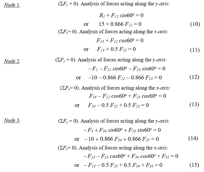
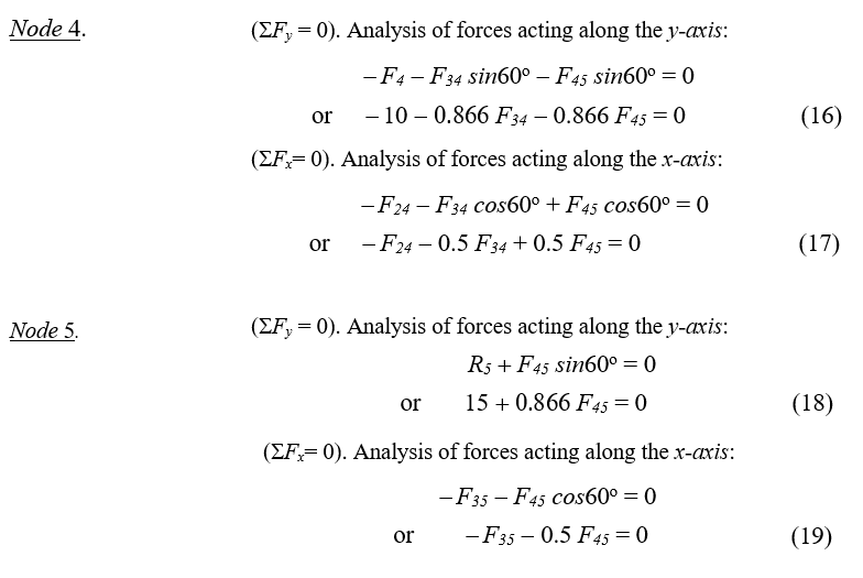
It is convenient to identify the forces on the truss elements making reference to the corresponding end nodes. For example, the force acting on the element joining nodes 1 and 2, is denoted F12, (Figure 10), and the force acting on element between nodes 4 and 3 is denoted F43. The vertical forces acting on nodes 2, 3, and 4, are denoted as F2, F3, and F4.


Step 2. Find the value of reaction forces on the end bottom of the truss (nodes 1 and 5)
Reactions are forces developed at the supports of a structure, to keep the structure in equilibrium. To find the reaction forces on the truss it is required to calculate the moments all the forces applied on the truss can produce, respect to every of the end bottom nodes.
By definition, the moment of a force is the product of the distance from the point to the point of application of the force and the component of the force perpendicular to the line of the distance:
M = F·d
The moment of a force M quantifies the turning effect or rotation the force can produce. In the case of a structure in equilibrium, the moment of all the forces applied has to be zero.
In this example (Figure 12), forces F1, F2 and F3, tend to rotate the truss clockwise respect to node 1, but the reaction force R5 on node 5 cancels this effect (Figure 12a), keeping the truss in equilibrium. This equilibrium condition is expressed mathematically as the sum of the moments of all forces and reactions equal to zero:
M1 = ƩF1· x1 = 0 (8)
= R1 · 0 – F2 · 2 - F3 · 4 - F4 · 6 + R5 · 8 = 0
where the minus signs indicate that the forces point in the negative direction.

These forces also tend to rotate the truss counter clockwise respect node 5, but the reaction force R1 on node 1 cancels this effect (Figure 12b). This equilibrium condition can be also expressed as:
M5 = ƩF1· x1 = 0 (9)
= R1 · 8 – F2 · 6 - F3 · 4 - F4 · 2 + R5 · 0 = 0
For this example, given F1 = F2 = F3 = 10 lbf, the value of reaction R5 can be found solving equation (8):
= R1 · 0 – 10 · 2 - 10 · 4 - 10 · 6 + R5 · 8 = 0
-120 + R5 · 8 = 0
R5 = 15 lbf
and the value of reaction R1 can be found solving equation (9):
= R1 · 8 – 10 · 6 - 10 · 4 - 10 · 2 + R5 · 0 = 0
R1 · 8 - 120 = 0
R1 = 15 lbf
Step 3. Analysis of Forces on Nodes using FBD and the equilibrium conditions ƩFy = 0 and ƩFx = 0.

For those experienced solving systems of linear equations, is going to be odd to have an overdetermined system for a truss structure (more equations than variables). However, we know from Algebra that even though most of the times an overdetermined system of equations has no solution, there are overdetermined systems of equations that have a solution. This is the case for this example.
In structural analysis, a truss is statically determinate when all the forces on its elements can be found by equations of statics alone. This is what we have in this example. In Step 4 we can verify that our system has a solution.
Step 4. Solve the System of Equations. Identify the obtained forces as Compressions (-) or Tensions (+)
Note to teacher: Continue using the Notetaking Sheet to help students to follow you during this long process. Is recommended to model how to the first four or five equations and then ask students to work in small groups to obtain the solutions for the rest of the equations.
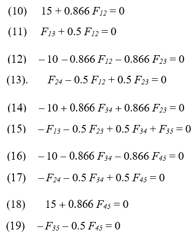
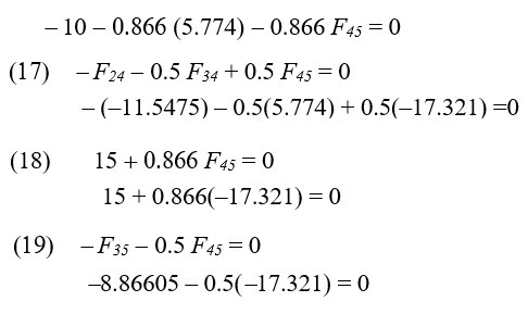
In this example, the substitution method is going to be used. The variables to solve are: F12, F13, F23, F24, F34, F35, and F45. F1, F2, F3, R1 and R5 are known constants: F1 = F2 = F3 = 10 lbf, and R1 = R5 = 15 lbf.
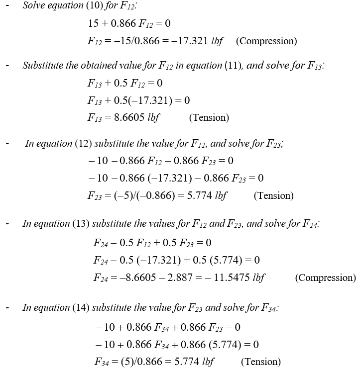
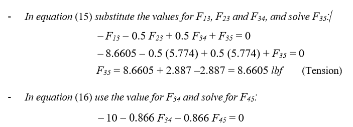
It is simple to verify that the obtained values for F34, F35 and F45 satisfy equations (17), (18), and (19):
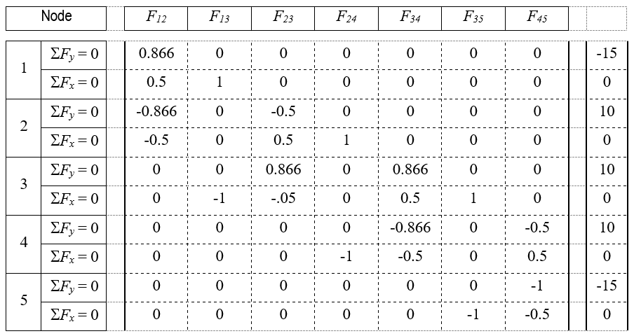
Step 5. Create the Matrix for the above System of Equations
Note: This simple concept is important in the computer graphic interface explained in Step 6. Continue using the Notetaking Sheet. Guide students to obtain the associated matrix for the system of equations (10)-(19):
Step 6. Spreadsheets to Calculate Trusses
The procedure shown in Steps 1 - 5 is also used to solve other type of trusses, larger trusses, isosceles triangles or right triangles trusses, or when different loads are applied on the nodes. However, a larger truss will produce a larger system of equations, which it will be more difficult to solve by hand. For example, a Warren truss with nine equilateral triangles will produce a 19 x 22 system of linear equations. Also, every change in the triangles angles or in the loads values will require to perform all the calculations again.
Because the procedure is always the same, no matter the truss type or the number of elements, it is possible to use Excel or Google Sheets and create a graphical interface to perform all these calculations automatically, giving the loads and the elements’ angles as entry values.
Note to teacher: It is not in the scope of this lesson that students write themselves such interface. But for those advanced or curious, the procedure used to write this interface is detailed in the Annex.

This section summarizes how to use a very friendly computation interface developed by the author in Google Sheets. This graphic interface:
- Calculates the tensions-compressions for the Warren truss, Warren with Vertical truss, Pratt truss, and Howe truss.
- Estimates maximum strength of the trusses considering the kind of wood used and element’s thickness.
- Gives solutions when the truss is supported only on its bottom end nodes, the truss’ diagonal elements are round or square, and the truss’ rails are square.

Visit this Trusses Calculations webpage for more information.
In this web page there are four interfaces (Figure 14(a)) corresponding to the four different trusses. Truss size is defined here by the number of triangles in the truss. The following table summarizes truss types and sizes:
| Truss Types | Size (No. of triangles) |
| Warren | 3, 5, 7, 9, 11 (equilateral-isosceles) |
| Warren w/ Verticals | 3, 5, 7, 9, 11 (equilateral-isosceles) |
| Pratt | 6, 10, 14, 18 (right triangles) |
| Howe | 6, 10, 14, 18 (right triangles) |
To activate an interface on a PC, laptop, or tablet, click on the gray square at the right top of the window. (Figure 14(a)); click on the window when using a cellphone. (Note: these sheets are open to the public for distribution and to copy; the master will always remain locked.)
Once the spreadsheet is active, you can see its different sections (Figure 14(b)):
- A truss diagram with entries for the loads on each node.
- Two entries for the truss elements’ length and angle respect the horizontal.
- Cells to select the truss elements’ thickness and kind of wood they are made of.
- Section displaying the calculated truss elements’ tensions-compressions
- The operational section: matrix associated to the system of linear equations obtained from the FBD’s, the inverse matrix, and the solutions of the system of equations.
Students only have to input values in the cells in sections (1) and (2), select round or square diagonals (3), and select the elements’ wood type and thickness in the cells in section (4) (Figure 15). Sections (5) and (6), or other cells do not have to be altered. The tension-compression on the truss elements are automatically calculated once values in sections (1), (2), (3) or (4) are entered.
Next is suggested a guided practice to teach students the efficient use of these interfaces.
Important: Before this practice, reset the values in the Warren truss in the third sheet: 5 in the loads, 5 in the triangles’ base length, select round diagonals, and hardwood + 1/8 in the Diagonals entries, and also Hardwood + 1/8 in the Rails entries. There is a hardcopy of these instructions in the Notetaking Sheet, make enough copies for students. You will also need to be familiar with how to access and work with Google Drive and Google Sheets with a cellphone or computer. Use projections of these notes to support the practice steps.
Tell students: Because it is required in the associated activity to estimate the strength of the bridge to build, and this bridge is going to be larger than the one solved here, the number of nodes is going to increase, so the resulting system of equations will be larger, and the time to solve will be longer. For example, the analysis of a Warren truss with 11 equilateral triangles will produce a linear system with 26 equations and 23 variables!
But there is more. Any change in the loads values, or truss angles, will require to repeat all the analysis again. Repeating by hand the same process, even after the simplest change, is not really efficient.
You are going to learn how to use a graphic interface to easily perform all this calculations. You should have a basic knowledge of Google Sheets or Excel, a Google Drive account, and your cellphone or a computer with internet access.
These interfaces are very easy to use. You have in your notes a hardcopy of these instructions in your notes for quick reference.
First you have to open the webpage where these interfaces are located. Open Google Chrome in your cellphones or on the computer and type the next address:
In this page select the Warren Truss interface. Click on this window to open the interface, and click on the Open button at the top of the document. (You will be required to use your Google account here.) Once the worksheet is open you con scroll this and identify the different parts of the graphic interface (Show to students Figure 15).
You can easily see the cells where you can input information. Do not type anything yet. Because this document is shared to every one of you, so every change made by one of you is going to be displayed in all other cellphones and computers. For this little practice it is necessary you work with your own copy of this document. So create your own copy in your Google Drive, using the commands Share & export + Make a copy, give a new name to the file and save it in your Drive. You will work now in your saved file.
Note to Teacher. It is very important you inform students that even though the original file cells that do not have to be modified are protected, the copies they save possibly will not be protected. So ask them to be very careful and not to modify or erase other cells but the indicated in the practices.
Your first assignment is to use the interface to calculate the Warren truss with three equilateral triangles we have solved in class. You know the correct solutions for this problem, so the interface, if correctly developed, will give you the same answers. Click on the cells next to the truss nodes (show Figure 16), and type the number 10 + ENTER in each one. Select now the cell for triangles’ base length and type 4 + ENTER. Verify the diagonal’s angle is 60°. Check the numbers below the legend “Tensions-Compressions on Truss Elements”, Are these the same as the previously obtained? (Give some time to students to do this and then display the Warren truss interface with these values)

Once you verified that the interface gave the same values, you can use the interface for more complex calculations. Your next assignment is to overload the little truss. Change the 10 lbf load on the central bottom node (Node 3) by 65 lbf, and check the new tensions-compressions. What do you see now?
The expected answer is: four cells changed color. Ask to students now: What does this mean? Check in the color code table. The answer is: the four diagonal elements break under this new load. The next question to students is: Assuming you need a bridge able to support this load, what could be the solution to this problem. The expected answer is: use a stronger material.
Continue saying: Let’s first change the shape of the diagonal elements from round to square, what happened now? The expected answer is: Only two diagonals are broken now. Ask students: Why is this possible? You only changed a round element of 1/8 inch dimeter by a square of 1.8 inch side? Draw on the board a square representing 1/8 inch and inside a circle with the same diameter to help students with their reasoning. It is expected they see that the square’s area is greater than the circle’s area, and therefore it is a thicker, and consequently, a stronger element.
Continue with the next: Change the diagonals to “round” again, and go now to the cells under the legend “Wood Compressive Strength – Truss Elements Strength. Here you have two options: Choose a different wood or choose a thicker element. Begin with the second option, click on the “Diameter” and “Side” cells and select thicker elements than 1/8. Select the next in size element. (Students will find 3/16 for Diagonals, and Rails). What happened now? Students should answer something like: The thicker element of 3/16 inch resists this new load.
Ask students now to return Diagonals and Rails thicknesses to 1/8. Now ask them to change wood to Birch in both Diagonals and Rails, and ask students: What happened now? Students should answer: Birch is a stronger wood, 1/8 inch elements of this wood can resist the load 1/8 Hardwood elements cannot.
In the last part of this practice, students should independently manipulate the larger trusses. Assign problems from the last section of the Notetaking Sheet, four per student. Here is the first problem of this list:
Find the minimum diagonals and rails thicknesses for a hardwood Warren truss 20 inches long, made up with nine equilateral triangles that are able to resist a load of 50 lbf on every top node and 100 lbf on every bottom node (Figure 17).

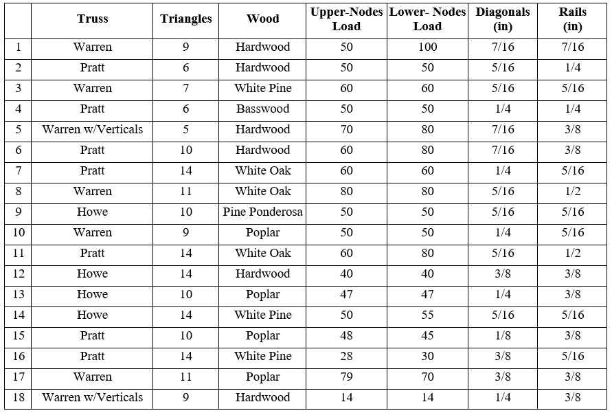
The next table contains the approximate solutions for the practice problems at the end of the Notetaking Sheet. There is really more than one acceptable answer for every problem, depending on the wood type and thickness, or if round or square diagonals are used. The next table shows some possible answers to the proposed problems.
A last remark about the graphic interfaces. The wood options in these worksheets include only the most common dowels can be found in stores: hardwood, pine, basswood, poplar, oak, and birch.
During this assignment move around the room and check students’ work and provide the necessary help and support. It is very important they understand completely the use (and limitations) of these interfaces.
Associated Activities
- Trust in the Truss: Design a Wooden Bridge - In this activity students design, construct, and test the strength of a wooden truss bridge and satisfy certain conditions like span, strength, and cost. Students perform the truss bridge strength estimation using a graphic interface that determine stress-compression on the truss elements using the method of joints.
Lesson Closure
To check the overall understanding of the lesson, ask students to write an exit note summarizing the steps used to solve a truss:
- Define the vertical loads magnitude and their location on the truss.
- Assume that the bridge is supported only at the bottom end nodes, and that the bridge and every node is at equilibrium.
- Perform the analysis of moments these loads produce respect the bottom ends to determine the reactions there.
- Perform on each node the analysis of forces using FBD’s to obtain the corresponding pair of equilibrium equations.
- Solve the obtained system of equations using the substitution method.
Ask some students to read aloud these notes. Be sure they have clear understanding of all these steps and their sequence. Make the necessary corrections.
Vocabulary/Definitions
bridge: A structure that is built over a railroad, river, or road so that people or vehicles cross from one side to the other in a safe way.
center of moment: The actual point about which a force causes rotation.
compression: Force that is transmitted through a solid when it is pulled tight by forces acting from opposite ends. The tension force is directed along the length of the solid and pulls equally against the acting forces on the object’s opposite ends.
equilibrium: In Physics, the condition of a system when neither its state of motion nor its internal energy state tends to change with time. It is also defined as the condition in which the total force acting on an object is zero.
equilibrium conditions: Forty-components of all the acting forces be equal to zero: ∑Fx = 0, ∑Fy = 0
force: In Physics, a force is any interaction that, when unopposed, will change the motion of an object. Force can also be described intuitively as a push or a pull. A force has both magnitude and direction, making it a vector quantity. When analyzed in two dimensions, a force F is separated in components along the x-y axes, using the force’s magnitude, its angle with the horizontal axis, and basic right triangle trigonometry.
free body diagram: In Physics and Engineering, a graphical illustration used to visualize the applied forces, movements, and resulting reactions on a body in a given condition. A tool used to solve the various forces acting on an object. It is used to minimize the complexity of any problem.
linear equation: An equation between two variables that gives a straight line when plotted on a graph.
method of joints: A method widely used by civil engineers to find the forces acting on a structure. It considers that every portion of the structure is in equilibrium and every joint with the bars connected to it as a free body. Truss members are assumed to be hinged together at the joints and all bars connecting at the joint do not pass through the joint. Bar forces do not produce any moments or rotation at the joint, then only two equations of statics are used to find the unknown forces: ∑F_x = 0, ∑F_y = 0
moment of a force: In Statics, it is a measure of the tendency of a force to cause a body to rotate about a specific point or axis. The magnitude of the moment is defined as the product of the magnitude of the perpendicular force (F), and the arm’s length (d).
rigid body: It is a solid body in which deformation is zero or so small that can be neglected. The distance between any two given points on a rigid body remains constant in time regardless of external forces exerted on it. A rigid body is usually considered as a continuous distribution of mass.
sigma notation: A convention used to write out a long sum in an abbreviated way, consisting in the capital letter S from the Greek alphabet, Sigma (∑), followed by an indexed term representing the elements or numbers to add: ∑x_i
substitution method: A sequence of algebraic steps to solve systems of equations, that for a 2x2 system with x-y variables follows the next way: Step 1: Solve one of the equations for either x = or y = . Step 2: Substitute the solution from step 1 into the other equation. Step 3: Solve this new equation. Step 4: Solve for the second variable in the first equation, using the value obtained in step 3
system of equations: A collection of two or more equations with a same set of unknowns. The equations in the system may be linear or non-linear.
tension: It is the force that is transmitted through a solid when it is pulled tight by forces F acting from opposite ends. The tension force is directed along the length of the solid and pulls equally against the acting forces on the object’s opposite ends.
truss: A regular structure or frame built with straight members with end point connections and forces that act only at these end points. No member is continuous through a joint.
truss bridge: A bridge whose load-bearing superstructure is composed of a truss, a structure of connected elements usually forming triangular units. The connected elements (typically straight) may be stressed from tension, compression, or sometimes both in response to dynamic loads.
Assessment
Pre-Lesson Assessment
Pre-Test: Give students the Pre-Assessment to test students’ understanding of the use of the substitution method to solve linear equations.
Lesson Summary Assessment
Check: Check students’ Notetaking Sheet and give a grade for completeness, clarity, and neatness. Make clear that these notes are going to be the most important reference during the associated activity, Trust in the Truss: Design, Construction, and Testing of a Wooden Truss Bridge.
Homework
There is no a homework for this lesson, but teacher may optimize class time assigning to students watch videos related with the content of this lesson. These videos are available at www.sophia.org.
Additional Multimedia Support
There is available a set of video-tutorials for every one of the topics covered in this lesson. Make sure students know they have this on-line help. Bridges Project: https://www.sophia.org/playlists/bridges-project
Subscribe
Get the inside scoop on all things Teach Engineering such as new site features, curriculum updates, video releases, and more by signing up for our newsletter!More Curriculum Like This

High school students learn how engineers mathematically design roller coaster paths using the approach that a curved path can be approximated by a sequence of many short inclines. They apply basic calculus and the work-energy theorem for non-conservative forces to quantify the friction along a curve...

Building on their understanding of graphs, students are introduced to random processes on networks. They walk through an illustrative example to see how a random process can be used to represent the spread of an infectious disease, such as the flu, on a social network of students.

References
Benson, Harris: University Physics. Revised Edition. Chapter 2 Vectors. John Wiley & Sons. 1996
Learn Civil Engineering. Structure Engineer Section Review / AM Section. Mechanics of Materials-Tension and Compression. http://www.learncivilengineering.com/wp-content/themes/thesis/images/structural-engineering/PE-reviewStructure-Mechanics-of-Materials-Tension-and-compression.pdf
Mr. Wayne’s Classroom. Free Body Diagrams. The Basics. http://www.mrwaynesclass.com/freebodies/reading/index01.html
NCDOT North Carolina Department of Transportation. Historic Bridges.
https://www.ncdot.gov/projects/ncbridges/historic/types/?p=17
Arbabi, F. Structural Analysis and Behavior. McGraw-Hill Inc. 1991
Pinsdaddy. Steels Pin Connections. http://www.pinsdaddy.com/steel-pin-connections_PDE*7M5xqrsuQ099UuT1wYt2ME6U6BxL5UlfXt969ao/pxhere. Steel Rivet Connections. https://pxhere.com/en/photo/908147
University of North Carolina at Charlotte. Learning Activity #3. Analyze and Evaluate a Truss.
https://webpages.uncc.edu/~jdbowen/1202/learning_activities_manual/Learning_Activity_3.pdf
University of North Carolina at Charlotte. Learning Activity #1. Build a Model of a Truss Bridge. https://webpages.uncc.edu/~jdbowen/1202/learning_activities_manual/Learning_Activity_1.pdf
University of N. C. Charlotte. Learning Activity #5. Design and Build a Model Truss Bridge.
https://webpages.uncc.edu/~jdbowen/1202/learning_activities_manual/Learning_Activity_5.pdf
The Historical Marker Database. “The Pratt Through-Truss Bridge.” Patuxent Branch Trail. https://www.hmdb.org/marker.asp?marker=20498
Mathalino. “Engineering Mathematics. Method of Joints, Analysis of Simple Trusses” https://www.mathalino.com/reviewer/engineering-mechanics/method-joints-analysis-simple-trusses
Journal of the American Institute of Architects. “Design Flaws Contributed to Fatal FIU Bridge Collapse.” Press Release. November 29, 2018
https://www.architectmagazine.com/practice/design-flaws-contributed-to-fatal-fiu-bridge-collapse_o
Copyright
© 2020 by Regents of the University of Colorado; original © 2019 Miguel RamirezContributors
Miguel R Ramirez, Galena Park High SchoolSupporting Program
Miguel R. Ramirez, high school math teacher, Texas, USAAcknowledgements
The author expresses his thanks to Michelle Merritt, Galena Park ISD Director for Secondary Mathematics, Shameel Ali, Galena Park High School, Math Specialist.
Last modified: June 13, 2025
User Comments & Tips