
Quick Look
Grade Level: 11 (11-12)
Time Required: 6 hours
(4 sessions of 90 minutes)
Expendable Cost/Group: US $35.00
Group Size: 4
Activity Dependency: None
Subject Areas: Algebra, Computer Science, Geometry, Number and Operations, Physics, Problem Solving
NGSS Performance Expectations:

| HS-ETS1-2 |
| HS-ETS1-3 |
| HS-ETS1-4 |
Quick Look

- Grade Level:
- 11 (11 – 12)
- Time Required:
- 6 hours
(4 sessions of 90 minutes)
- Group Size:
- 4
- Subject Areas:
-
Algebra Computer Science Geometry Number and Operations Physics Problem Solving -
NGSS Performance Expectations:
HS-ETS1-2 HS-ETS1-3 HS-ETS1-4

Summary
In this activity students design, construct, and test the strength of a wooden truss bridge and satisfy certain conditions like span, strength, and cost. Students perform the truss bridge strength estimation using a graphic interface that determine stress-compression on the truss elements using the method of joints. Students consider their materials’ hypothetical costs and test their constructed bridges to verify load strength. Expect that the bridges can resist at least 90% of their estimated strength and in case of failure, students have to determine the possible causes.Engineering Connection
Engineers approach problem-solving in a variety of ways, including fully understanding of a problem, compiling knowledge of all possible variables, and applying their experience to find a solution. Through these concepts, as well as by using the engineering design process, engineers design durable, economically affordable, and safe solutions. Like civil engineers, students must perform the following steps in this activity: take into account the constraints of a problem; verify the strength of the designed structure using a mathematical model; define steps for the construction process; and construct the model according to the design. They also must perform the corresponding corrections or changes as necessary; and test the model to verify its compliance with the requirements.
Learning Objectives
After this activity, students should be able to:
- Develop a plan and a schedule for completion of a design and construction project.
- Perform the appropriate calculations to determine the tensions-compressions produced by loads on the elements of a truss bridge.
- Select the appropriate materials to build a bridge, keeping in mind strength and cost requirements.
- Define several engineering terms such as tension and compression, stress, strain and elasticity of materials; identify the truss bridge parts.·
- Analyze quantitatively how bridges work under load.
- Work as a team to construct a model consistent with a design and given specifications.
Educational Standards
Each Teach Engineering lesson or activity is correlated to one or more K-12 science,
technology, engineering or math (STEM) educational standards.
All 100,000+ K-12 STEM standards covered in Teach Engineering are collected, maintained and packaged by the Achievement Standards Network (ASN),
a project of D2L (www.achievementstandards.org).
In the ASN, standards are hierarchically structured: first by source; e.g., by state; within source by type; e.g., science or mathematics;
within type by subtype, then by grade, etc.
Each Teach Engineering lesson or activity is correlated to one or more K-12 science, technology, engineering or math (STEM) educational standards.
All 100,000+ K-12 STEM standards covered in Teach Engineering are collected, maintained and packaged by the Achievement Standards Network (ASN), a project of D2L (www.achievementstandards.org).
In the ASN, standards are hierarchically structured: first by source; e.g., by state; within source by type; e.g., science or mathematics; within type by subtype, then by grade, etc.
NGSS: Next Generation Science Standards - Science
| NGSS Performance Expectation | ||
|---|---|---|
|
HS-ETS1-2. Design a solution to a complex real-world problem by breaking it down into smaller, more manageable problems that can be solved through engineering. (Grades 9 - 12) Do you agree with this alignment? |
||
| Click to view other curriculum aligned to this Performance Expectation | ||
| This activity focuses on the following Three Dimensional Learning aspects of NGSS: | ||
| Science & Engineering Practices | Disciplinary Core Ideas | Crosscutting Concepts |
| Design a solution to a complex real-world problem, based on scientific knowledge, student-generated sources of evidence, prioritized criteria, and tradeoff considerations. Alignment agreement: | Criteria may need to be broken down into simpler ones that can be approached systematically, and decisions about the priority of certain criteria over others (trade-offs) may be needed. Alignment agreement: | |
| NGSS Performance Expectation | ||
|---|---|---|
|
HS-ETS1-3. Evaluate a solution to a complex real-world problem based on prioritized criteria and trade-offs that account for a range of constraints, including cost, safety, reliability, and aesthetics, as well as possible social, cultural, and environmental impacts. (Grades 9 - 12) Do you agree with this alignment? |
||
| Click to view other curriculum aligned to this Performance Expectation | ||
| This activity focuses on the following Three Dimensional Learning aspects of NGSS: | ||
| Science & Engineering Practices | Disciplinary Core Ideas | Crosscutting Concepts |
| Evaluate a solution to a complex real-world problem, based on scientific knowledge, student-generated sources of evidence, prioritized criteria, and tradeoff considerations. Alignment agreement: | When evaluating solutions it is important to take into account a range of constraints including cost, safety, reliability and aesthetics and to consider social, cultural and environmental impacts. Alignment agreement: | New technologies can have deep impacts on society and the environment, including some that were not anticipated. Analysis of costs and benefits is a critical aspect of decisions about technology. Alignment agreement: |
| NGSS Performance Expectation | ||
|---|---|---|
|
HS-ETS1-4. Use a computer simulation to model the impact of proposed solutions to a complex real-world problem with numerous criteria and constraints on interactions within and between systems relevant to the problem. (Grades 9 - 12) Do you agree with this alignment? |
||
| Click to view other curriculum aligned to this Performance Expectation | ||
| This activity focuses on the following Three Dimensional Learning aspects of NGSS: | ||
| Science & Engineering Practices | Disciplinary Core Ideas | Crosscutting Concepts |
| Use mathematical models and/or computer simulations to predict the effects of a design solution on systems and/or the interactions between systems. Alignment agreement: | Both physical models and computers can be used in various ways to aid in the engineering design process. Computers are useful for a variety of purposes, such as running simulations to test different ways of solving a problem or to see which one is most efficient or economical; and in making a persuasive presentation to a client about how a given design will meet his or her needs. Alignment agreement: | Models (e.g., physical, mathematical, computer models) can be used to simulate systems and interactions—including energy, matter, and information flows—within and between systems at different scales. Alignment agreement: |
Common Core State Standards - Math
-
(+) Recognize vector quantities as having both magnitude and direction. Represent vector quantities by directed line segments, and use appropriate symbols for vectors and their magnitudes (e.g., v, |v|, ||v||, v).
(Grades
9 -
12)
More Details
Do you agree with this alignment?
-
(+) Use matrices to represent and manipulate data, e.g., to represent payoffs or incidence relationships in a network.
(Grades
9 -
12)
More Details
Do you agree with this alignment?
-
Solve systems of linear equations exactly and approximately (e.g., with graphs), focusing on pairs of linear equations in two variables.
(Grades
9 -
12)
More Details
Do you agree with this alignment?
-
(+) Represent a system of linear equations as a single matrix equation in a vector variable.
(Grades
9 -
12)
More Details
Do you agree with this alignment?
-
(+) Find the inverse of a matrix if it exists and use it to solve systems of linear equations (using technology for matrices of dimension 3 × 3 or greater).
(Grades
9 -
12)
More Details
Do you agree with this alignment?
International Technology and Engineering Educators Association - Technology
-
Students will develop abilities to apply the design process.
(Grades
K -
12)
More Details
Do you agree with this alignment?
-
Students will develop an understanding of the attributes of design.
(Grades
K -
12)
More Details
Do you agree with this alignment?
-
Students will develop an understanding of engineering design.
(Grades
K -
12)
More Details
Do you agree with this alignment?
-
Students will develop an understanding of and be able to select and use construction technologies.
(Grades
K -
12)
More Details
Do you agree with this alignment?
-
Engineering design is influenced by personal characteristics, such as creativity, resourcefulness, and the ability to visualize and think abstractly.
(Grades
9 -
12)
More Details
Do you agree with this alignment?
-
A prototype is a working model used to test a design concept by making actual observations and necessary adjustments.
(Grades
9 -
12)
More Details
Do you agree with this alignment?
-
Identify the design problem to solve and decide whether or not to address it.
(Grades
9 -
12)
More Details
Do you agree with this alignment?
-
Evaluate the design solution using conceptual, physical, and mathematical models at various intervals of the design process in order to check for proper design and to note areas where improvements are needed.
(Grades
9 -
12)
More Details
Do you agree with this alignment?
-
Evaluate final solutions and communicate observation, processes, and results of the entire design process, using verbal, graphic, quantitative, virtual, and written means, in addition to three-dimensional models.
(Grades
9 -
12)
More Details
Do you agree with this alignment?
-
Infrastructure is the underlying base or basic framework of a system.
(Grades
9 -
12)
More Details
Do you agree with this alignment?
-
Structures are constructed using a variety of processes and procedures.
(Grades
9 -
12)
More Details
Do you agree with this alignment?
-
The design of structures includes a number of requirements.
(Grades
9 -
12)
More Details
Do you agree with this alignment?
-
Structures can include prefabricated materials.
(Grades
9 -
12)
More Details
Do you agree with this alignment?
-
Illustrate principles, elements, and factors of design.
(Grades
9 -
12)
More Details
Do you agree with this alignment?
-
Determine the best approach by evaluating the purpose of the design.
(Grades
9 -
12)
More Details
Do you agree with this alignment?
-
Optimize a design by addressing desired qualities within criteria and constraints.
(Grades
9 -
12)
More Details
Do you agree with this alignment?
-
Develop a plan that incorporates knowledge from science, mathematics, and other disciplines to design or improve a technological product or system.
(Grades
9 -
12)
More Details
Do you agree with this alignment?
State Standards
Texas - Math
-
apply mathematics to problems arising in everyday life, society, and the workplace;
(Grades
9 -
12)
More Details
Do you agree with this alignment?
-
use a problem-solving model that incorporates analyzing given information, formulating a plan or strategy, determining a solution, justifying the solution, and evaluating the problem-solving process and the reasonableness of the solution;
(Grades
9 -
12)
More Details
Do you agree with this alignment?
-
select tools, including real objects, manipulatives, paper and pencil, and technology as appropriate, and techniques, including mental math, estimation, and number sense as appropriate, to solve problems;
(Grades
9 -
12)
More Details
Do you agree with this alignment?
-
communicate mathematical ideas, reasoning, and their implications using multiple representations, including symbols, diagrams, graphs, and language as appropriate;
(Grades
9 -
12)
More Details
Do you agree with this alignment?
-
formulate systems of equations, including systems consisting of three linear equations in three variables and systems consisting of two equations, the first linear and the second quadratic;
(Grades
9 -
12)
More Details
Do you agree with this alignment?
-
solve systems of three linear equations in three variables by using Gaussian elimination, technology with matrices, and substitution;
(Grades
9 -
12)
More Details
Do you agree with this alignment?
-
develop and use a sinusoidal function that models a situation in mathematical and real-world problems; and
(Grades
9 -
12)
More Details
Do you agree with this alignment?
-
determine the values of the trigonometric functions at the special angles and relate them in mathematical and real-world problems.
(Grades
9 -
12)
More Details
Do you agree with this alignment?
-
determine the value of trigonometric ratios of angles and solve problems involving trigonometric ratios in mathematical and real-world problems;
(Grades
9 -
12)
More Details
Do you agree with this alignment?
-
use trigonometry in mathematical and real-world problems, including directional bearing;
(Grades
9 -
12)
More Details
Do you agree with this alignment?
-
use vectors to model situations involving magnitude and direction;
(Grades
9 -
12)
More Details
Do you agree with this alignment?
-
apply mathematics to problems arising in everyday life, society, and the workplace;
(Grades
9 -
12)
More Details
Do you agree with this alignment?
-
use a problem-solving model that incorporates analyzing given information, formulating a plan or strategy, determining a solution, justifying the solution, and evaluating the problem-solving process and the reasonableness of the solution;
(Grades
9 -
12)
More Details
Do you agree with this alignment?
-
create and use representations to organize, record, and communicate mathematical ideas;
(Grades
9 -
12)
More Details
Do you agree with this alignment?
-
analyze mathematical relationships to connect and communicate mathematical ideas; and
(Grades
9 -
12)
More Details
Do you agree with this alignment?
-
display, explain, or justify mathematical ideas and arguments using precise mathematical language in written or oral communication.
(Grades
9 -
12)
More Details
Do you agree with this alignment?
Texas - Science
-
express and manipulate relationships among physical variables quantitatively, including the use of graphs, charts, and equations.
(Grades
9 -
12)
More Details
Do you agree with this alignment?
-
express and interpret relationships symbolically in accordance with accepted theories to make predictions and solve problems mathematically, including problems requiring proportional reasoning and graphical vector addition.
(Grades
9 -
12)
More Details
Do you agree with this alignment?
-
calculate the effect of forces on objects, including the law of inertia, the relationship between force and acceleration, and the nature of force pairs between objects;
(Grades
9 -
12)
More Details
Do you agree with this alignment?
Materials List
The truss bridge model in this activity has to be built using only wood dowels, craft-sticks, and carpenter’s glue. Some extra tools and materials like junior hacksaw, sandpaper, waxed paper, masking tape, wood, rulers, squares, drafting protractors, clamps, and paint for finishing, will be also used.
The dowels thickness, kind of wood, and quantity will depend on the truss assigned, its size, and required strength. Next is a generic list of materials, with approximate costs (In USD):
Use the following materials for bridges with a span of 20-28 inches:
- 1/4 in. x 36 in. square dowel ($1.00)
- 1/8 or 1/4 in. x 36 in. round ($0.90). Optional for truss elements. Trusses can be made with the ¼ square dowel; There are also bags of round dowels of different diameters, 12 inches long ($3.00)
- 5/16 in. x 4 ½ in. craft sticks ($3.00 bag w/100)
- 3/4 in. x 6 in. jumbo craft sticks ($6.00 box w/300)
Use the following materials for bridges with a span of 29-36 inches:
- 5/16 in. x 36 in. square dowel ($1.20)
- 1/4 in. x 36 in. round dowel ($0.50) Optional for truss elements. Trusses can be made also with square dowel
- 5/16 in. x 4 ½ in. craft sticks
- 15/16 in. x 8 in. extra or super jumbo craft sticks ($3.00 bag w/30)
Students may change the thickness dowels, or use only square dowels, depending on their designs.
Each group needs:
- wooden dowels and craft sticks (see amounts and sizes above), or have students purchase their own materials outside of class
- carpenter’s glue, such as Titebond II Premium wood glue
- junior hacksaw
- sandpaper, 100 and 220 grain found in a 3M general purpose packet)
- wax paper ($3.00 /roll)
- grid easel paper with a 1’’ x 1’’ grid, 2.5 ft x 2.08 ft
- meter stick or yard stick
- spring clamps or bar clamps
- drafting triangles, 30 cm – 12 in ruler, and protractor
- masking tape
- 40 x 12 cardboard sheets, two per group
- video recording device, such as a smartphone
- Project Overview and Activity Rubric
To share with the entire class on Day 4 (see notes in the Procedure for details):
- computer projector to display electronic format posters
- heavy objects, such as textbooks, to load models
- optional: a harness to load the bottom of the bridge
Worksheets and Attachments
Visit [www.teachengineering.org/activities/view/ind-2472-trust-truss-design-wooden-bridge-activity] to print or download.Pre-Req Knowledge
Students should have an understanding of the following mathematical concepts: concept of force, analysis of forces using free body diagrams, truss bridges structures, a basic knowledge of Google Sheets, how to solve a truss by the method of joints, how to manipulate a graphic user interface to calculate tensions-compressions on truss elements (See Associated Lesson), and basic drawing skills.
Introduction/Motivation
During the Associated Lesson students learned about truss structures, the method of joints, and simple graphic interfaces to calculate tensions-compressions on truss elements under different loads. The understanding of these topics makes students capable to determine if a truss structure is going to resist a given load, and/or the maximum load the structure can resist. Therefore, students are ready to analyze a simple truss structures with rigid elements in a similar way professional engineers do.
During the lesson, you learned about the components of a truss structure and you used mathematics and tools to analyze and determine tensions-compressions on elements of truss structures. Now, you will apply all this knowledge. Visualize yourselves as professional engineers designing, calculating, and constructing a wooden truss bridge prototype. Your overall challenge is as follows:
- You will be assigned one of the next four trusses: Warren, Warren w/Vertical, Pratt, or Howe, and you will have to design a small truss bridge able to cover a given span between 20 and 36 inches, with elements able to support a specified load.
- Using the graphic interface to select the exact thickness of the wood truss elements, you will assess the bridge’s strength under a specified load and calculate the costs.
- No nails, staples, or screws allowed! You will build this bridge using only wood dowels and carpenter’s glue.
- Finally, you will create a research poster summarizing and explaining your work and you will present and test your bridge in class. You will load your bridge to verify that it is as strong as you estimated. In case your bridge fails, you will have to infer possible causes.
Are you ready for the challenge?
Procedure
Background
1. Truss Bridge Parts
It is important students make correct references to each part of a truss bridge. Figure 1 summarizes these parts. Always refer to the truss bridge parts with the correct names and make students in some way memorize them.

2. Estimation of Maximum Loads for Wood Elements
The strength of a wooden truss bridge will depend on the strength of the wood used, the glue’s strength, and on the bridge’s construction. Be aware of the wood the dowels are made from. There is a big difference between balsa wood and hardwood and between hardwood and birch.
Wood glues differs in strength, and a glued joint strength also depends on joint type and the strength of the wood fibers. A test performed on a cross grain joint made with a strong wood as hard maple provides the breaking forces (see Figure 2):

Sometimes the companies give specific information about their products’ strengths. For example, an internet search shows the strength for Titebond III, which is 4,000 psi, and for Titebond II, which is 3,750 psi. All these numbers depend on the type of test performed.
Students may also research the strength of different kind of woods. Values for the wood commonly used in the dowels found at hardware stores are as follows in Figure 3.

Do not take the above numbers as absolute values, but as an average for that kind of wood. These values change for the different wood sub-species, and factors such as water content. Students may perform research on the internet to find exact values.
Wood has several kinds of strength. For a rough, general estimate of strength, refer to the specific gravity or density of the wood. When you need more detailed information, there are additional choices.
Engineers measure the compressive or crushing strength by loading a block of wood parallel to the grain until it breaks. They measure the bending strength by loading a block perpendicular to the grain.
Both are measured in pounds per square inch (psi). Stiffness is determined by applying a load to a beam until it deflects a certain amount, measured in millions of pounds per square inch (Mpsi). To find hardness, engineers drive a metal ball halfway into the wood’s surface. The force used is recorded in pounds (lbf). In each case, the higher the number, the stronger the wood.
Table in Figure 4 shows values for common woods used in the United States. How can we calculate the strength of a dowel using the above values?
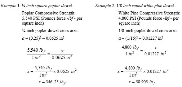
Because the elements of a truss bridge are only under tension or compression forces, the number to consider is the compressive or crushing strength. Knowing this number per square inch, the crushing strength for a dowel of a cross section area a can be calculated using a simple proportion.

Before the Activity
- Before you begin this activity with the students, engage yourself in the design and construction of a wooden bridge, using the graphing interface to perform all the required calculations, and by following (and testing) all the construction steps here listed. You may find a better way to do one or more of the steps listed in this activity. Your little bridge will be a good sample for students, and a good practice for you to completely understand each one of the parts of this activity and identify the most difficult steps and potential mistakes.
- Have ready enough copies of the Project Overview and Rubric for the students.
- Gather tools or materials; check if your school may be able to provide some materials to students.
- Have the Bridge Costs Estimation Worksheet on hand for students to review.
With the Students
Project Overview
Begin the activity distributing the Project Overview and Rubric. Give students the overview of the activity from the rubric.
- Group Work
- Because the amount of work in this activity, it is recommended you work in groups of up to four students. You must organize yourselves very well, and distribute the work load very efficiently, in order to accomplish in this short time all the parts of this activity.
- You will have to perform part of the work in class and part of the work at home.
- Bridge Design and Calculation
- Every team will be randomly assigned a different problem to solve.
- You will be assigned one of four trusses: Warren, Warren w/Verticals, Pratt or Howe, and you will create a design fulfilling the requirements in your assigned problem.
- You will use the graphic interface to determine the minimum thickness and the appropriate wood required to build a truss bridge supporting the specified load, and with a cost you can afford with your assigned budget. (See the Bridge Costs Estimation Worksheet.)
- Bridge Construction
- You will construct your bridge, based in your design, using only wood and carpenters glue.
- Paint/decorate your bridge. Be creative.
- Bridge Presentation and Strength Test
- Create a poster summarizing objective, background, type of bridge used, design and construction process, calculated values for your bridge including maximum load able to hold, pictures of the final model.
- Present your bridge in class. Give a brief explanation of the work done using your poster.
- Test your bridge strength.
- Record a video of your presentation and bridge strength test.
Day 1. Truss Bridge Design
Give students time to organize themselves in work groups. Keep a record of the teams’ members. Find a way to assign randomly each group one of the next problems. See some important observations in the Activity Problem Solutions:
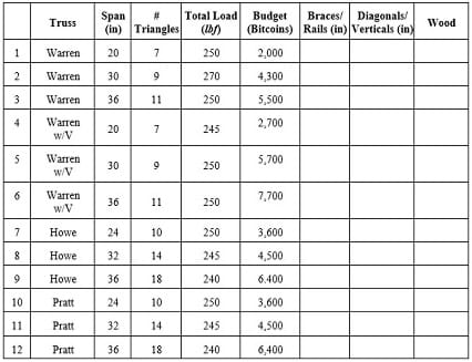


Explain that in this activity, just like a real engineering project, materials have a cost. In this case the dowels to build the bridge will have a hypothetical price depending on the wood’s quality and thickness. Show them the price list in the Project Overview and Activity Rubric. They have to find the optimal minimum thickness of the elements and wood that fits their budgets. They can use the Bridge Costs Estimation Worksheet to determine their purchases.
Using their designs, students should estimate how many dowels they will need to build the bridge. There is an example of materials quantification for the design in Figure 7 in the Project Overview and Activity Rubric. In this session, students can also browse the web find the stores where they can buy the dowels and other materials they need.
Day 2. Truss Bridge Construction
Students must have the necessary materials and the drawings of their truss bridge design to begin the model construction. Instruct students to tape their drawings on the cardboard sheets, and cover them with wax paper (Figure 6). They can begin cutting of the trusses’ elements using the junior hacksaw, a sturdy table or desk, and clamps (Figure 7).

Students have to cut the pieces at the measured length on the drawing. Some of these pieces, mainly the diagonals and braces, will need some sanding at the ends in order to fit them in the truss. The first piece students have to cut are bridge’s rails: four single pieces only. In a truss structure, no element is continuous through a joint; however, so save time the rails are going to be continuous. This fact does not affect greatly the bridge strength because diagonal elements are the first ones to fail in a truss structure.
The next elements to cut are the truss gussets. These little squares will have be cut from the craft-sticks. (see Figure 8). Students will need as many gussets as nodes in the drawings.
Once the rails and gussets are cut, these have to be glued. Place the gussets on the drawings at the truss.


Diagonals must be glued to the rails and have good contact with these elements. Only gluing the gussets to the diagonals, and not touching the rails, will make a weak structure. The gussets in this model are only to help retain the glue, as the gussets are thin and will not resist a heavy load.
While some of the team members are gluing diagonals, others may build the bridge’s struts— the elements that join the trusses. These are made from the same dowels as the rails. To make assembly easier, they can be glued to craft sticks (Figure 10.a). To save some work, the width of the bridge can be the same length as the craft sticks. Use the 3/4” x 6” jumbo craft sticks for bridges 20-24 inches long, and the 15/16” x 8” super jumbo craft sticks for bridges 28-36 inches long.

Struts are cut about a half-inch shorter than the craft-sticks, and then glued to the center of the craft sticks, so these “new” compound struts’ ends have an entry to fit the rails. Same as the gussets, the added craft sticks help retain glue to make a stronger bond between the strut and the rail.
Day 3. Truss Bridge Assembling and Presentation Poster Draft
After 24 hours, the carpenter’s glue should have firmly bonded to the trusses. Assemble the bridge by gluing the trusses and struts. Carefully remove the trusses from the drawings and take one of the drawings and tape the bridge’s bottom struts on the bottom nodes so they are perpendicular and aligned to the bottom rail (Figure 11.a)
Add glue to the ends of the struts and place the trusses in position (Figure 11.b), use a drafting triangle to be sure the trusses are vertical. Use something heavy like textbooks to keep the trusses vertical (Figure 11.c). Glue the top struts to the trusses and verify trusses are still vertical. Keep using heavy objects as supports to keep the structure still (Figure 11.d). Wait at least an hour before you remove the supports.

While the glue dries, students may begin their presentation posters using the following template, either electronically or as a hardcopy:
- Tittle of project and students’ names
- Outline of the project
- Bridge truss design drawing, with a brief description/history of the truss used
- Example of a free body diagram for the analysis of forces on a truss node
- System of equations resulting from the analysis of forces; this can be a snapshot of the matrix in the graphic interface
- Screenshot of the specified load applied on the truss
- Calculated tensions-compressions on truss elements
- Pictures of the bridge model. Some pictures of the construction process
Depending how much students want to reinforce their bridges, students can insert braces diagonally between the struts (Figure 12.a). Bracing is recommended, but not mandatory. Students should also begin the bridge’s deck; this floor can be easily made gluing craft-sticks on the bottom rails (Figure 12.b).Finally, students may add final touches or bridge decorations if they desire. (Figure 12.c).

Day 4. Bridge Presentation and Testing
Allow 48 hours after assembling and bracing the bridge to test so the glue can fully cure. Along with presenting the finished models, students may explain their designs, using the poster they created as guideline and support. In addition, follow these preparation steps:
- Secure a computer projector to display electronic format posters.
- Use two sturdy tables or stands for bridge testing; they should be able to hold all the weight used to test the bridges.
- Have heavy objects to load the models on hand, such as textbooks. These are safer than iron weights, and are also heavy (an average textbook weighs 5-6 pounds). Teachers usually have one or two class sets in the classroom, that easily may weigh 250 pounds altogether.
- Optional. A harness to load also the bottom of the bridge. (Figure 13). This is important because usually calculations are performed considering a load on the bottom nodes. The tension-compression forces on the truss elements are different to the tension-compressions produced when all the load is applied on the top nodes only. You can verify this using the Google Sheets graphing interface.
- In case that is not possible for teacher to fabricate such a harness, use sport bags filled with textbooks or weights and hook them to the beams.
The Project Overview and Activity Rubric contains some suggestions and formats to grade the presentation. It is also required for students to record a video of their presentation and test. This is a good record for teacher and an analysis tool for students in case their bridge fails.
Vocabulary/Definitions
bending strength: Shows the load the wood can withstand perpendicular to the grain; also known as the modulus of rupture. (Example: how much weight can one hang on a peg before it breaks.)
center of moments: The actual point about which a force causes rotation.
compression: The force that is transmitted through a solid when it is pulled tight by forces F acting from opposite ends. The tension force is directed along the length of the solid and pulls equally against the acting forces on an object’s opposite ends.
compressive strength: How much of a load a wood species can withstand parallel to the grain. (Example: how much weight the legs of a table support before they buckle.)
equilibrium: The condition of a system when neither its state of motion nor its internal energy state tends to change with time; also defined as the condition in which the total force acting on an object is zero.
equilibrium condition: For forces acting in two dimensions over a point, a requirement that the sum of the x-components and the sum of the y-components of all the acting forces be equal to zero: ∑Fx = 0, ∑Fy = 0
force: Any interaction that, when unopposed, will change the motion of an object; it can also be described intuitively as a push or a pull. A force has both magnitude and direction, making it a vector quantity. When analyzed in two dimensions, a force F is separated in components along the x-y axes, using the force’s magnitude, its angle with the horizontal axis, and basic right triangle trigonometry.
free body diagram: A graphical illustration used to visualize the applied forces, movements, and resulting reactions on a body in a given condition; a tool used to solve the various forces acting on an object to minimize the complexity of any problem.
hardness: How resistant the surface of the wood is to scratches, dents, and other abuse.
method of joints: Used by civil engineers to find the forces acting on a structure, it considers that every portion of the structure is in equilibrium and every joint with the bars connected to it as a free body. Truss members are assumed to be hinged together at the joints and all bars connecting at the joint pass through the joint. Bar forces do not produce any moments or rotation at the joint, then only two equations of statics are used to find the unknown forces: ∑Fx = 0, ∑Fy = 0
modulus of elasticity: An indication of how much the wood will deflect when a load is applied perpendicular to the grain. Commonly known as “stiffness.”
moment of a force: A measure of the tendency of a force to cause a body to rotate about a specific point or axis. The magnitude of the moment is defined as the product of the magnitude of the perpendicular force (F), and the arm’s length (d).
rigid body: A solid body in which deformation is zero or so small that can be neglected. The distance between any two given points on a rigid body remains constant in time regardless of external forces exerted on it. A rigid body is usually considered as a continuous distribution of mass.
tension: The force that is transmitted through a solid when it is pulled tight by forces F acting from opposite ends; it is directed along the length of the solid and pulls equally against the acting forces on the object’s opposite ends.
truss: A regular structure or frame built with straight members with end point connections and forces that act only at these end points. No member is continuous through a joint.
truss bridge: The bridge whose load-bearing superstructure is composed of a truss, a structure of connected elements usually forming triangular units. The connected elements (typically straight) may be stressed from tension, compression, or sometimes both in response to dynamic loads.
Assessment
Pre-Activity Assessment
Lesson Review: Conduct the Associated Lesson that includes pre-assessments and covers the necessary concepts.
Activity Embedded Assessment
Monitor: Monitor the students’ work during class. The intensity of this activity means teachers can provide in-class assessment of the design and of the mathematical models needed to build the truss bridges. See rubrics on the Project Overview and Activity Rubric.
Post-Activity Assessment
Poster: The poster summarizing the work done, and the in-class explanation of the work done. See rubrics on the Project Overview and Activity Rubric for a guide on grading students’ posters and presentations.
Investigating Questions
Using calculation graphing interface, students can determine how changing some of the round elements under the greatest tension-compressions with square elements of the same thickness will significantly increase the strength of their bridge.
The next questions are oriented to help them to discover this concept. Teachers can give the Investigative Questions as homework or ask these in class.
(1). When you were doing the truss strength calculation, were all the truss elements under the same compression-stress?
Answer: No, the end diagonal elements have the greater tension-compression, and they are the first to break or fail.
(2). Did you notice any difference when you substituted a round element with a square element of the same thickness, or vice versa?
Answer: Yes, the square elements are stronger than the round elements of the same thickness.
(3). Can you estimate how much?
Answer: The direct way is to use the calculation graphic interface and see that a round hardwood 1/8” element has a strength of 36.938 lbf, while the 1/8” square element has a strength of 43.031 lbf. The ratio 43.031/36.938 = 1.273, this means that the square element is 27.3% stronger than the round element.
(4). Why do you think the square element is stronger?
Answer: Because the cross-section area of the square element is greater than the cross-section area of the round element.. The greater the cross section, the stronger the element.
(5). How many times is the area of a square of side L greater than the area of a circle of diameter L?
Answer: Calculating the ratio of the area of a square of side L to the area of a circle of diameter L: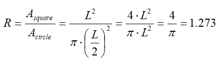
The area of the square with side L is 1.273 times (27.3%) greater than the area of the circle with diameter L.
(6). Considering your answers to the previous questions, what can you do to increase the strength of your bridge without changing all the diagonal elements and keeping the thickness requirement?
Answer: Replace the round elements under high tension-compression by square elements of the same thickness.
Troubleshooting Tips
Feel free to contact the author (e-mail: mramirez2@galenaparkisd.com, phone: 1-(832) 386-2888) to ask any questions related with this activity.
Activity Scaling
For lower grades:
Middle school students have the background and manual skills to do the design, cost analysis, and construction (without the mathematical analysis) using the following workflow:
- Choose or assign one of the activity problems.
- Create the corresponding truss design.
- Quantify the amount of materials based on their designs.
- Using the table of wood costs, have students find the materials within a budget.
- Cut the wood elements and assemble the bridge.
- Decorate their bridges.
- Present their bridges and explain how they calculated the costs to stay within the assigned budget.
- Put weight on the bridges to see if they hold the load. (They can also record the presentation and submit to teacher.)
Additional Multimedia Support
There is available a set of video tutorials for every one of the background topics necessary for this activity. Make sure students know they have this on-line help. Bridges Project: https://www.sophia.org/playlists/bridges-project.
Subscribe
Get the inside scoop on all things Teach Engineering such as new site features, curriculum updates, video releases, and more by signing up for our newsletter!More Curriculum Like This

Learn the basics of the analysis of forces engineers perform at the truss joints to calculate the strength of a truss bridge known as the “method of joints.” Find the tensions and compressions to solve systems of linear equations where the size depends on the number of elements and nodes in the trus...
Students learn about the types of possible loads, how to calculate ultimate load combinations, and investigate the different sizes for the beams (girders) and columns (piers) of simple bridge design. Additionally, they learn the steps that engineers use to design bridges.

Working as engineering teams, students design and create model beam bridges using plastic drinking straws and tape as their construction materials. Their goal is to build the strongest bridge with a truss pattern of their own design, while meeting the design criteria and constraints.

Students are presented with a brief history of bridges as they learn about the three main bridge types: beam, arch and suspension. They are introduced to two natural forces — tension and compression — common to all bridges and structures.

References
Benson, Harris: University Physics. Revised Edition. Chapter 2 Vectors. John Wiley & Sons. 1996
Learn Civil Engineering. Structure Engineer Section Review / AM Section. Mechanics of Materials-Tension and Compression. http://www.learncivilengineering.com/wp-content/themes/thesis/images/structural-engineering/PE-reviewStructure-Mechanics-of-Materials-Tension-and-compression.pdf
Mr Wayne’s Classroom. Free Body Diagrams. The Basics. http://www.mrwaynesclass.com/freebodies/reading/index01.html
NCDOT North Carolina Department of Transportation. Historic Bridges.
https://www.ncdot.gov/projects/ncbridges/historic/types/?p=17
Arbabi, F. Structural Analysis and Behavior. McGraw-Hill Inc. 1991
Pinsdaddy. Steels Pin Connections. http://www.pinsdaddy.com/steel-pin-connections_PDE*7M5xqrsuQ099UuT1wYt2ME6U6BxL5UlfXt969ao/
University of North Carolina at Charlotte. Learning Activity #3. Analyze and Evaluate a Truss.
https://webpages.uncc.edu/~jdbowen/1202/learning_activities_manual/Learning_Activity_3.pdf
University of North Carolina at Charlotte. Learning Activity #1. Build a Model of a Truss Bridge. https://webpages.uncc.edu/~jdbowen/1202/learning_activities_manual/Learning_Activity_1.pdf
University of N. C. Charlotte. Learning Activity #5. Design and Build a Model Truss Bridge.
https://webpages.uncc.edu/~jdbowen/1202/learning_activities_manual/Learning_Activity_5.pdf
The Historical Marker Database. “The Pratt Through-Truss Bridge.” Patuxent Branch Trail. https://www.hmdb.org/marker.asp?marker=20498
The Wood Database: Poplar. http://www.wood-database.com/poplar/
Woodgears.ca: Glue Strength Testing. https://woodgears.ca/joint_strength/glue.html
The Wood Whisperer: Differences Between Titebond Glues. August 4, 2010.
Workshop Companion: The Nature of Wood. 3. Wood Strength.
http://workshopcompanion.com/KnowHow/Design/Nature_of_Wood/3_Wood_Strength/3_Wood_Strength.htm
Woodwork Web. Wood Strengths. https://www.woodworkweb.com/woodwork-topics/wood/146-wood-strengths.html
Copyright
© 2020 by Regents of the University of Colorado; original © 2019 Miguel RamirezContributors
Miguel R Ramirez, Galena Park High SchoolSupporting Program
Miguel R. Ramirez, high school math teacher, Texas, USAAcknowledgements
The author expresses his thanks to Michelle Merritt, Galena Park ISD Director for Secondary Mathematics, Shameel Ali, Galena Park High School, Math Specialist.
Last modified: July 20, 2023
User Comments & Tips