Quick Look
Grade Level: High school; also scalable for middle school
Time Required: 1 hour (wild guess!)
Subject Areas: Computer Science, Physical Science, Physics, Problem Solving, Science and Technology

Maker Challenge Recap
Whether you want to light up a front step or a bathroom, it helps to have a light come on automatically when darkness falls. For this maker challenge, students work through the engineering design process to create their own night-lights using Arduino microcontrollers, photocells and (supplied) code to sense light levels and turn on/off LEDs as they specify. As they build, test, and control these night-lights, they learn about voltage divider circuits and then experience the fundamental power of microcontrollers—controlling outputs (LEDs) based on sensor (photocell) input readings and if/then/else commands. Then they are challenged to personalize (and complicate) their night-lights—such as by using delays to change the LED blinking rate to reflect the amount of ambient light, or use many LEDs and several if/else statements with ranges to create a light meter. The possibilities are unlimited!
Maker Materials & Supplies
- computer, Windows or Mac
- Arduino software; download from https://www.arduino.cc/en/software
- SparkFun RedBoard or Arduino Uno microcontroller and programming cable; an Arduino Inventors Kit is recommended, such as at SparkFun
- breadboard, jumper wires, 330-ohm resistors and 10k-ohm resistors
- photocell, aka light-dependent resistor or light-sensitive resistor, such as a mini photocell at SparkFun
- light-emitting diodes (LEDs), ~1-6+ per project
Worksheets and Attachments
Visit [www.teachengineering.org/makerchallenges/view/cub-2136-build-night-light-arduino-photocell] to print or download.Subscribe
Get the inside scoop on all things TeachEngineering such as new site features, curriculum updates, video releases, and more by signing up for our newsletter!More Curriculum Like This

Students learn about the function and components of the human nervous system, which helps them understand the purpose of our brains, spinal cords, nerves and five senses. In addition, how the nervous system is affected during spaceflight is also discussed.

Students gain a rigorous background in the primary human "sensors," as preparation for comparing them to some electronic equivalents in the associated activity. Students learn the concept of "stimulus-sensor-coordinator-effector-response" to describe the human and electronic sensory processes.
Kickoff
In today’s challenge, we are going to design our own sensors and response systems using microcontrollers. Think about your own sensors—eyes and skin—and actuators—muscles.
Imagine that you are walking down the street and someone grabs your arm and activates your touch sensors. If you look with your vision sensors and see that it is your friend trying to get your attention, how would you respond? A high five or a hug is pretty common!
Now imagine the same scenario, walking down the street and someone grabs your arm and activates your touch sensors. This time, when you look with your vision sensors you see that it is a stranger. In this case, your response might be quite different—perhaps a step away or even a push or a run!
Keep in mind that in both cases, the sensors are the same, but based on the information received from the sensors, the response is quite different!
In our imaginary scenarios, your brain processed the information from the sensors and sent signals to your muscles on the next actions to take. In our night-light project today, an Arduino microcontroller will function as the “brain” of your project and it will control an LED. Let’s get started!
Resources
- Refer to the Engineering Design Process hub on TeachEngineering to guide your students through the challenge.
- Utilize the Engineering Design Process Notebook when writing through the engineering design process.
- In the SIK Guide, see Circuit 1 for the LED circuit and Circuit 6 for the photo resistor: https://cdn.sparkfun.com/datasheets/Kits/RedBoard_SIK_3.2.pdf
- Analog to Digital Conversion tutorial by SparkFun: https://learn.sparkfun.com/tutorials/analog-to-digital-conversion
- Photocell Hookup Guide tutorial by Sparkfun: https://learn.sparkfun.com/tutorials/photocell-hookup-guide?_ga=2.123678091.1266611760.1497627477-514920872.1497627477
- Voltage Dividers tutorial by SparkFun: https://learn.sparkfun.com/tutorials/voltage-dividers
- For the LED hookup, refer to the Building Arduino Light Sculptures maker challenge
- if/else reference by Arduino: https://docs.arduino.cc/built-in-examples/control-structures/ifStatementConditional
Maker Time
In engineering, one effective way to complete a project is to begin by mastering the fundamentals, and then to layer on complexity as you gain familiarity with the project. Just as infants first crawl, then walk, then run, if you start slow, your small successes grow and evolve into larger, successful projects.
The basic challenge: Use a photocell to sense the light levels in a room and based on those readings, turn an LED on or off.
The recipe for student success in this project:
- Take sensor readings to make sure that the sensor circuit is working.
- Determine your team’s threshold reading for darkness; this is location and photocell sensor dependent, so the “threshold for darkness” reading will be different for each team.
- Based on this threshold, turn on and off an LED. It is okay to start with the light attached to pin 13 on the Arduino board, but the goal is to hook up an external LED.
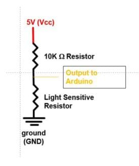
The sensor for this project is a photocell, also called a light-sensitive resistor. The photocell resistance changes in response to the brightness of the light that hits its surface. If the photocell is placed in a dark environment, the resistance is greater than 10,000 ohms. In extremely bright environments, the resistance is less than 1,000 ohms. However, Arduino can only sense voltages. So, we need to place this simple and inexpensive sensor into a circuit known as a voltage divider, as shown in Figure 1.

(While the electrical nuances of the voltage divider are outside of the scope of this challenge, once students have a working circuit, have them play with this voltage divider.)
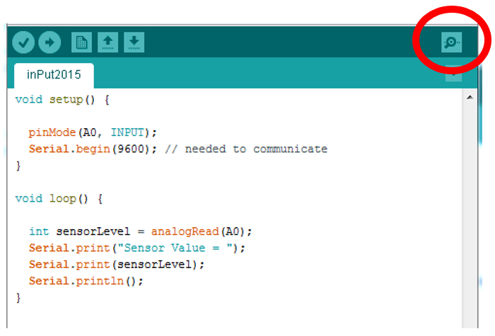
Now, to handle the code to obtain readings from the sensor, see Figure 2.
(Walk students through the Figure 2 code.)
Notice the two commands in the setup function. The first command tells Arduino that we are looking for an input on pin A0. Since we need a range of values, we know that we need an Arduino analog pin. Since it will be coming into the Arduino from a sensor, it needs to be an input pin.
Remember: Outputs from sensors are inputs to the Arduino.
The next command, Serial.begin(9600) tells Arduino that we want to send values that it receives to the computer. The cord between your Arduino and computer is called a USB cord, which stands for universal serial bus, and 9600 is the default rate of communication between the two devices, so it is a good beginning value with which to start.
In the loop function, the first thing we do is declare a variable and assign the value corresponding to the voltage read from the sensor circuit. As drawn in Figure 1, this value is between 0-5 volts, but what we will see on our screen is a value from 0-1023, with 0 corresponding to 0 volts and 1023 corresponding to 5 volts. This is known as analog-to-digital conversion. (As necessary, refer students to a tutorial about this that is listed in the Resources section.) Once the value is read, the values are output to the screen using the Serial.print and Serial.println (adds a carriage return) commands.
To view the readings, you need to start the serial monitor. The easiest way to do this is to click on the magnifying glass in the upper right corner (see Figure 2).
After you get the readings, feel free to really play with the circuit.
The “threshold for darkness” is the reading at which it is dark enough to turn on a light. Does it have to be totally dark to turn a light? (Answer: Usually it is nice to have a light come on under dim—not totally dark—conditions!)
To find your threshold for darkness, first try blocking the sensor with a finger. Then try a piece of paper or a book. Due to manufacturing differences in the photocells and different ambient light conditions, each group’s readings will be different, so every group will have a different threshold for darkness! If the circuit matches the design, expect the readings to go down to about 100 or so when it is really bright and above 700 as the light is blocked. What values are you getting?
Once you have a circuit that works and know your darkness threshold—the fun begins! Without disturbing the just-built sensor circuit, on another area of the breadboard create an LED circuit. Call up a blink code in a different Arduino sketch (if needed, review this process using the Introduction to Arduino: Getting Connected and Blinking LEDs, maker challenge) and make sure that your LED is blinking. The great part about microcontrollers is that we can isolate the circuits. We do not need to wire the light directly to the sensor! Once the LED is working alongside the sensor, combine the two circuits and code to create a night-light.
If the sensor values are above the threshold, that means it is dark and you want the light on. Else, if the sensor values are below your threshold, it is light out and you want the light off. This is known as an if-then-else statement. (To get the correct Arduino syntax, refer students to the if/else reference listed in the Resources section.)
Challenge projects: Once you have working basic night-lights, you are ready for a challenge project.
- Can you control the rate at which an LED blinks based off of the amount of incoming light? Hint: Use the blink code, but put the sensor value in a delay.
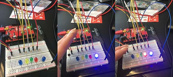
- Can you create your own light meter with five LEDs to display how much incoming light is hitting the photo resistor? Hint: Use several if/else statements with different ranges.
- What happens to sensor readings if the 10k-ohm resistor and photocell are switched in the voltage divider? (Answer: Sensor readings become very high—above 950 when bright and around 500 when covered.)

Wrap Up
Now that you can sense the light levels in your room, what other “things” would you like to sense? (Possible student answers: Temperature, humidity, dustiness, etc.)
Now that you are controlling an output (LED) with an input (light sensor), you are starting to use the power of the microcontroller. What other different kinds of outputs would you like to control? What could you do with a motor? How about a servo?
Other students have used Arduino systems to control their window blinds, based on the time of day or the amount of sunlight present. Another student connected an alarm clock to a coffeemaker in another room. Can you think of a project where you could really use an Arduino? What would you like to control? What problem would you like to solve?
Tips
Students often confuse inputs and outputs, so it is important to emphasize that an output from a sensor is an input to the Arduino. This is a critical and often misunderstood concept.
If a sensor reading is always 0, then it is likely connected to ground instead of the photocell resistor junction. Likewise, if a sensor reading is 1023, it is likely connected directly to power.
If sensor values do not change with light levels, verify that the breadboard is connected to the Arduino. Commonly, students connect a sensor to the breadboard rails, but forget to bring these rails back to the Arduino. Remember. No connections between the breadboard and Arduino exist until you make them.
Students often forget to declare the LED as an OUTPUT in the second part of this exercise. If the LED is on but dim, make sure to declare the pin you are trying to use in the setup function using the command: pinMode(pin#, OUTPUT); also check that you are not using a 10k-ohm resistor (brown, black, orange) by mistake.
If the LEDs are not lighting up, check to make sure that:
- the wire is placed in the correct row of the breadboard
- the LED is facing the correct direction
Copyright
© 2017 by Regents of the University of ColoradoContributors
Daniel GodrickSupporting Program
ITL Program, College of Engineering and Applied Science, University of Colorado BoulderAcknowledgements
This activity was developed by the Integrated Teaching and Learning Program in the College of Engineering and Applied Science at the University of Colorado Boulder.
Last modified: May 24, 2022


User Comments & Tips