Quick Look
Grade Level: 9 (9-12)
Time Required: 5 hours
This engineering project covers several days of class time and includes a field trip to a local college or manufacturing lab with a universal testing machine.
Expendable Cost/Group: US $7.00
Group Size: 2
Activity Dependency: None
Subject Areas: Geometry, Measurement, Physical Science
NGSS Performance Expectations:

| HS-ETS1-2 |
| HS-ETS1-3 |
Summary
In this activity, students learn about creating a design directly from a CAD (computer-aided design) program. Teams design towers in CAD and manufacture the parts with a laser cutter. A competition determines the tower design with the best strength:weight ratio. Students also investigate basic structural truss concepts and stress concentrations. Partnership with a local college or manufacturing center is necessary for project completion (testing).Engineering Connection
Engineers often revise a design in a computer modeling program many times before finalizing the project. Many CAD (computer-aided design) programs can be used in conjunction with other programs or equipment to mathematically replicate the effects of loads on structures or to machine prototype parts from a variety of materials. Engineers must balance many different constraints and parameters when designing parts and structures. A solid bar is almost always stronger than an I-beam of the same size, but is also heavier and more expensive. Often, engineers redesign to make it lighter and/or more cost effective without sacrificing too much strength .
Learning Objectives
After this activity, students should be able to:
- Define a stress concentration.
- Describe what geometrical shapes influence higher stress concentrations.
- Use calculations to determine a strength vs. weight ratio of a prototyped tower.
- Explain why engineers do not always use solid pieces of materials in design.
Educational Standards
Each TeachEngineering lesson or activity is correlated to one or more K-12 science,
technology, engineering or math (STEM) educational standards.
All 100,000+ K-12 STEM standards covered in TeachEngineering are collected, maintained and packaged by the Achievement Standards Network (ASN),
a project of D2L (www.achievementstandards.org).
In the ASN, standards are hierarchically structured: first by source; e.g., by state; within source by type; e.g., science or mathematics;
within type by subtype, then by grade, etc.
Each TeachEngineering lesson or activity is correlated to one or more K-12 science, technology, engineering or math (STEM) educational standards.
All 100,000+ K-12 STEM standards covered in TeachEngineering are collected, maintained and packaged by the Achievement Standards Network (ASN), a project of D2L (www.achievementstandards.org).
In the ASN, standards are hierarchically structured: first by source; e.g., by state; within source by type; e.g., science or mathematics; within type by subtype, then by grade, etc.
NGSS: Next Generation Science Standards - Science
| NGSS Performance Expectation | ||
|---|---|---|
|
HS-ETS1-2. Design a solution to a complex real-world problem by breaking it down into smaller, more manageable problems that can be solved through engineering. (Grades 9 - 12) Do you agree with this alignment? |
||
| Click to view other curriculum aligned to this Performance Expectation | ||
| This activity focuses on the following Three Dimensional Learning aspects of NGSS: | ||
| Science & Engineering Practices | Disciplinary Core Ideas | Crosscutting Concepts |
| Design a solution to a complex real-world problem, based on scientific knowledge, student-generated sources of evidence, prioritized criteria, and tradeoff considerations. Alignment agreement: | Criteria may need to be broken down into simpler ones that can be approached systematically, and decisions about the priority of certain criteria over others (trade-offs) may be needed. Alignment agreement: | |
| NGSS Performance Expectation | ||
|---|---|---|
|
HS-ETS1-3. Evaluate a solution to a complex real-world problem based on prioritized criteria and trade-offs that account for a range of constraints, including cost, safety, reliability, and aesthetics, as well as possible social, cultural, and environmental impacts. (Grades 9 - 12) Do you agree with this alignment? |
||
| Click to view other curriculum aligned to this Performance Expectation | ||
| This activity focuses on the following Three Dimensional Learning aspects of NGSS: | ||
| Science & Engineering Practices | Disciplinary Core Ideas | Crosscutting Concepts |
| Evaluate a solution to a complex real-world problem, based on scientific knowledge, student-generated sources of evidence, prioritized criteria, and tradeoff considerations. Alignment agreement: | When evaluating solutions it is important to take into account a range of constraints including cost, safety, reliability and aesthetics and to consider social, cultural and environmental impacts. Alignment agreement: | New technologies can have deep impacts on society and the environment, including some that were not anticipated. Analysis of costs and benefits is a critical aspect of decisions about technology. Alignment agreement: |
Common Core State Standards - Math
-
Solve simple rational and radical equations in one variable, and give examples showing how extraneous solutions may arise.
(Grades
9 -
12)
More Details
Do you agree with this alignment?
International Technology and Engineering Educators Association - Technology
-
Evaluate the design solution using conceptual, physical, and mathematical models at various intervals of the design process in order to check for proper design and to note areas where improvements are needed.
(Grades
9 -
12)
More Details
Do you agree with this alignment?
-
Develop a plan that incorporates knowledge from science, mathematics, and other disciplines to design or improve a technological product or system.
(Grades
9 -
12)
More Details
Do you agree with this alignment?
State Standards
Colorado - Math
-
Solve linear equations and inequalities in one variable, including equations with coefficients represented by letters.
(Grades
9 -
12)
More Details
Do you agree with this alignment?
-
Attributes of two- and three-dimensional objects are measurable and can be quantified.
(Grades
9 -
12)
More Details
Do you agree with this alignment?
Materials List
Each group needs:
- access to a computer with basic CAD program
- 10" x 22" x 1/8" sheet of acrylic plastic
To share with the entire class:
- a variety of plastic adhesives for students to use when assembling their towers (available at hardware or hobby stores)
- several small files for smoothing rough plastic edges
- access to a laser cutter
- access to a college or manufacturing lab for compression testing
- enough safety glasses for half the class to wear at once (ask to borrow from the testing laboratory)
Pre-Req Knowledge
Basic 2-dimensional drafting skills with any CAD program
Introduction/Motivation
Have you ever drawn a really cool design but had no way of building it exactly how you drew it? With today's new manufacturing machinery, it is easier to go from drawing to reality. Engineers can design parts or prototypes of parts on their computers using CAD (computer aided drawing) programs. Examples of CAD programs are SolidWorks®, AutoCAD®, Inventor® and Ideas®. Once complete, engineers take their designs to a machine and simply press 'print' to build the design out of different materials. CNC (computer numerically controlled) machines can manufacture solid 3-D designs out of plastic or metals. Rapid prototyping machines, also known as stereolithography machines, can create just about any design imaginable using plastic. Finally, laser cutters can cut intricate 2-D designs out of plastic. So, don't worry, even if you are not the greatest artist with a pencil, you can always draw a straight line or a perfect circle with the computer to help you out.
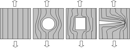
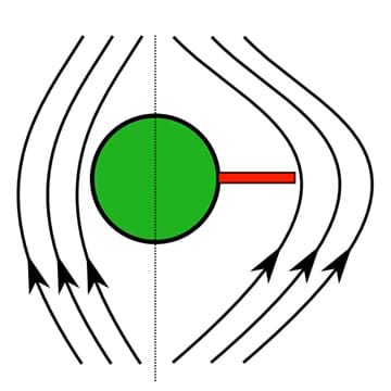
Stress (σ) is defined as force divided by area and has units of Pascals or psi. One Pascal is a Newton per square meter and 1 psi is a pound per square inch. Normally, stress is distributed evenly throughout a material. However, sometimes stress can build up and intensify in certain areas. This is known as a stress concentration and occurs at holes and other sudden changes in geometry. A general rule is that sharper, more sudden edges cause higher stress concentrations (Figure 2 illustrates this principle). Circles have lower stress concentrations than rectangles, and cracks have the highest stress concentrations of all. This is why materials usually break shortly after cracks are formed. Coincidentally, cracks are usually formed at areas of high stress concentrations.
Think about a crack in a car windshield. Cracks in windshields usually start when a high stress concentration is applied to the window, such as a pebble or rock thrown from the roadway. Then, as a crack is formed, it weakens the windshield and eventually breaks. If you catch the initial crack in the windshield in time, you can drill a little circle around the end of the crack and keep the windshield from breaking or cracking further.
Often, engineers cut holes or odd geometries into materials even though they cause stress concentrations. Sometimes they do this to reduce material cost or weight, or even insert something through the hole. If material is removed carefully, the strength of the material is not be drastically affected. Engineers aim for high strength:weight or strength:cost ratios. Remember, smooth-rounded edges always minimize stress concentrations compared to jagged-sharp edges.
In designing tall buildings or long bridges, engineers use truss supports to prevent twisting. Trusses are bars or beams to help increase the stability of the structure. In simple structures, truss supports are most effective at a 45° angle from the horizon. When two truss supports cross, they are often called cross supports because they form a 90° angle just like a cross.
Engineers utilize today's new prototyping techniques to quickly see if their designs have any mistakes that they may have overlooked on paper or on the computer. Using CNC (computer numerically controlled) machines, rapid prototyping machines and laser cutters, engineers can quickly produce scaled replicas of their designs and test where or not stress concentrations are problematic or if the truss system is correctly designed.
For this project, we are going to work as engineers and design prototype towers out of acrylic plastic. We are going to design our towers in a CAD program and test the strength:weight ratio of our towers in a manufacturing lab, using a universal testing machine. Let's see if we can use what we have just learned about stress concentrations to design a small Tower O' Power that is really strong.
Fun Fact: Martial artists use the truss support principle in self-defense by keeping their elbows and knees at 45° from full extension when blocking attacks. This helps stabilize their bodies using the same principles engineers use to stabilize structures.
Procedure
Before the Activity
- Make sure students have access to computers with a CAD program
- Order 1 sheet of 10" x 22" x 1/8" acrylic for each group. Place order with an acrylic plastic distributor such as:
- Colorado Plastic Products at 303-443-9271
- Interstate Plastics at http://www.interstateplastics.com
With the Students
Part I: Tower Design
- Introduce students to the ideas of stress, stress concentrations and truss supports via the activity introduction.
- Explain the following rules of the Tower O' Power competition:
- Their tower must be 12" tall.
- The tower cross-section must fit within a 4" x 4" square, though the tower does not necessarily have to be square.
- The pieces of the tower will be laser cut from 1/8" thick acrylic.
- Each piece of acrylic is 10" x 22".
- They can use any adhesive they want to construct their tower. (Note: This is a critical part of the design, and can cause failure if poor adhesives are used.)
- Finally, most importantly, the wining tower will be decided by which tower has the highest strength:weight ratio. (Strength equals the maximum load the tower holds, and weight equals the weight of the tower). (Hint: The winning tower may not necessarily hold the most load.)
- Give students a deadline for when CAD drawing deadlines are due (1-2 weeks).
- Explain the CAD drawing specifications:
- Drawings must be 2-dimensional. (The laser cutter only cuts by moving the laser left and right.)
- Drawings must have all tower pieces fit into a 10" x 22" rectangle.
- Drawings must be saved as the .DXF file format (Verify with whomever is doing the laser cutting if any other file formats are acceptable.)
Part II: Laser Cutting & Design Deadline
- If you have not already done so, pick up acrylic sheets from the plastics distributor.
- Collect all designs as .DXF files (or other acceptable files) from students, and save them on a CD ROM or USB Flash-Drive.
- Take students' designs and acrylic sheets to be laser cut. (Note: The process of laser cutting is relatively quick, but cutting many towers is time consuming. On average, expect each tower to take about 20 minutes to cut. Make sure to plan adequate time for this process.) Some helpful hints:
- Although increasing the laser's speed and power decreases cutting time, if the speed is increased too much, good cuts will not be accomplished and some pieces will not be fully cut.
- One or two practice runs may be a good idea to optimize the laser's settings and save time in the long run.
Part III: Tower Construction
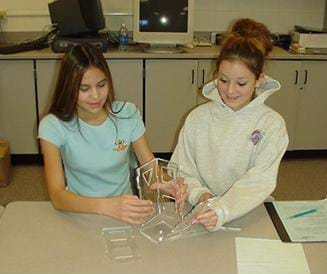
- Once all towers are cut, give the students their designed tower pieces to put together (see Figure 3).
- Advise students to use files to smooth out any sharp edges or burrs left by the laser cutting.
- Remind students that they can use any adhesive or glue they choose, and that it may have a large effect on the tower's performance.
- Set up a field trip for tower testing and a lab tour at a local college or manufacturing center. (Arrange for students to come early in the morning when the college and labs are typically less crowded.)
Part IV: Field Trip & Tower Testing Day
- Review engineering lab safety issues with students.
- Divide the class into two groups.
- Group 1 goes to an engineering lab to test their towers. (Arrange for a lab technician to operate compression tester.)
- Group 2 takes a tour of the facilities. (Arrange for a tour guide or extra chaperone.)
- In the testing group, have each group weigh its tower on a scale and then place the tower in a universal testing machine for compression testing. Make sure to label and record each tower's weight.
- Instruct each group member to put on safety glasses.
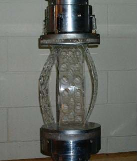
- Have the lab technician run and record each compression test on the universal compression machine. Note: Inform the technician that on average, towers are expected to hold 500-4000 lbs. This helps the technician determine the rate of loading of the towers. (Hint: Slower loading is more suspenseful and fun, but keep time in mind.) Figure 4 shows a tower during testing.
- Have students record the maximum load held by the tower for the strength:weight ratio calculation. Some towers may exhibit a decrease in load before breaking.
- After all of the towers have been tested, help clean up groups' broken pieces of plastic and return anu safety equipment borrowed from the lab (such as safety glasses).
- Have groups 1 and 2 switch and repeat steps 3-7.
Part V: Design Review
- Back in the classroom, have students calculate their strength:weight ratio or the strength divided by the weight of the tower. (Strength equals the maximum load the tower holds, and weight equals the tower weight.)
- Have students compare the strength:weigth ratio of their towers with the class and determine which tower had the highest strength:weight. Did the winning tower hold the most load?
- Discuss as a class what teams would do if they had a chance to redesign and test their towers again. Remind them that engineers often go through several design iterations before they complete projects.
Assessment
Pre-Activity Assessment
Brainstorming: As a class, have students engage in open discussion. Remind them that in brainstorming, no idea or suggestion is "silly." All ideas should be respectfully heard. Take an uncritical position, encourage wild ideas and discourage criticism of ideas. Have students raise their hands to respond. Write their ideas on the board. Ask the students:
- Why is it that planes and ships have oval windows instead of square windows that are common in homes and schools? (See answer in Post-Activity Assessment section.)
Activity Embedded Assessment
Question/Answer: Ask the students and discuss as a class:
- What has the highest stress concentration, a circle, square or crack? (Answer: A crack. A general rule is that sharper, more sudden edges cause higher stress concentrations. This is why materials usually break shortly after cracks are formed.)
- Coincidentally, what leads to cracks? (Answer: High stress concentrations lead to cracks.)
Post-Activity Assessment
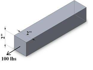
What's the Stress? Draw a 2" x 2" square bar that is subjected to 100 lbs of force (as drawn in Figure 5). Ask students to determine the stress experienced by the bar. Is the bar in tension or compression? (Answer: Stress = Force / Area = 100 lbs / (2"x2") = 25 psi in tension.)
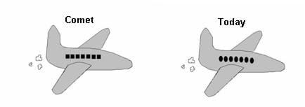
Engineering Problem Solving: In the mid 1950s, Great Britain's De Havilland's Comet airliner was dominating the world market until a series of mysterious crashes ruined the company. Figure 6 shows a comparison of the Comet and today's airplanes. What happened? (Answer: The square windows of the Comet caused a high enough stress concentration to create cracks. After a few years of flying, the repeated pressurization of the cabin caused a crack to form, grow, and eventually crash the plane. This is why we see oval windows in planes today.)
Safety Issues
Construction
- Sharp edges and burrs can be caused from the laser cutting process. Advise students to be careful and inspect their cut plastic pieces, looking for these defects, which can be easily removed with a nail file.
- Make sure students use caution with certain adhesives and glue. Hot glue can easily and quickly burn skin and some epoxies are harmful to inhale.
Field Trip
- Make sure students DO NOT wear open-toe shoes on the field trip, which may exclude them from entering engineering laboratories.
- Safety glasses are required in the lab; make sure enough pairs are available for every student.
- Remind students that they will be removed from the lab if they misbehave.
Troubleshooting Tips
Encourage students to be creative and design their towers with weight minimization in mind. Require them to smooth out sharp corners in their CAD designs, which can easily be done with 'round' or "fillet' CAD commands.
Choosing the right adhesive or glue can be critical. Hot glue can be dangerous and may dry too quickly, preventing accurate assembly of the tower pieces. Elmer's glue is non-toxic but weak in bonding plastic and takes too long to dry. Have the students research the best glue for the application. (Hint: In the past, Gorilla Glue® helped one team with an extremely light tower win the competition.)
Activity Extensions
More Tower Power: When testing the towers, the lab technician should be able to record the force exerted by the tower as it is compressed. This data can be saved and opened in Microsoft Excel®. Have students plot the Force of the Tower vs. Compression (units in lbs vs. inches or Newtons vs. mm). Engineers often use a normalized version of these plots (that is, stress vs. strain) when testing material properties. (Note: Consult the lab technician in advance to make sure s/he can save and copy the data for the students.)
Related Curriculum: Another activity on stress and strain can be found in the TeachEngineering collection at https://www.teachengineering.org/; search for: Mechanics Mania unit, Stressed and Strained Lesson, Breaking Beams activity.
Activity Scaling
For upper grades or more advanced students, have them create 3-D assemblies of their towers in CAD. Then, as a class, critique these 3-D assemblies and supply suggestions for ways to improve the designs.
Have more advanced students do the More Tower Power activity extension and add key points of interest on their plots, such as maximum load, compression to failure or any other points of interest they can think of.
Subscribe
Get the inside scoop on all things Teach Engineering such as new site features, curriculum updates, video releases, and more by signing up for our newsletter!More Curriculum Like This

Learn the basics of the analysis of forces engineers perform at the truss joints to calculate the strength of a truss bridge known as the “method of joints.” Find the tensions and compressions to solve systems of linear equations where the size depends on the number of elements and nodes in the trus...

Over several days, students learn about composites, including carbon-fiber-reinforced polymers, and their applications in modern life. This prepares students to be able to put data from an associated statistical analysis activity into context as they conduct meticulous statistical analyses to evalua...

Students learn about nondestructive testing, the use of the finite element method (systems of equations) and real-world impacts, and then conduct mini-activities to apply Maxwell’s equations, generate currents, create magnetic fields and solve a system of equations. They see the value of NDE and FEM...
References
Callister, William D. Jr., Material Science and Engineering: An Introduction, 7th Edition, John Wiley & Sons: New York, NY, 1996.
Public Broadcast System, Chasing the Sun, "Planes, Jet Age: DEHAVILLAND COMET," http://www.pbs.org/kcet/chasingthesun/planes/comet.html
Copyright
© 2006 by Regents of the University of ColoradoContributors
Christopher M. Yakacki; Malinda Schaefer Zarske; Diana Wiant; Janet YowellSupporting Program
Integrated Teaching and Learning Program, College of Engineering, University of Colorado BoulderAcknowledgements
The contents of these digital library curricula were developed by the Integrated Teaching and Learning Program under National Science Foundation GK-12 grant no. 0338326. However, these contents do not necessarily represent the policies of the National Science Foundation, and you should not assume endorsement by the federal government.
Last modified: February 25, 2020





User Comments & Tips