
Summary
Through this lesson and its series of hands-on mini-activities, students answer the question: How can we investigate and measure the inside of an object or its structure if we cannot take it apart? Unlike the destructive nuclear weapon test (!), nondestructive evaluation (NDE) methods are able to accomplish this. After an introductory slide presentation, small groups rotate through five mini-activity stations: 1) applying Maxwell’s equations, 2) generating currents, 3) creating magnetic fields, 4) solving a system of equations, and 5) understanding why the finite element method (FEM) is important. Through the short experiments, students become familiar with the science and physics being used and make the mathematical connections. They explore components of NDE and see how engineers find unseen flaws and cracks in materials that make aircraft. A pre/post quiz, slide presentation and worksheet are included.Engineering Connection
While the fields of mechanical and electrical engineering, physics and mathematics might seem quite different from each other to the average person, they not only depend on each other, but overlap in a way that enables the average engineer and physicist to be more successful in their own practices. Thus, mirroring the real world, this lesson requires basic knowledge of each of these fields.
In this lesson, students explore components of nondestructive evaluation—the term for a wide group of analysis techniques designed to inspect the properties of materials, components and systems without causing damage to them. Nondestructive testing methods introduce energy into materials as a way to locate flaws that cannot been seen that could lead to failures and potential catastrophe. Some common techniques are eddy current, magnetic particle, liquid penetrant, radiographic and ultrasonic. NDE is valuable for product evaluation, troubleshooting and research because the objects being examined—everything from concrete structures to planes, vehicles, machine parts and the human body—are not permanently damaged, and “invisible” defects can be found and measured.
Students also learn about finite element analysis as a numerical way to solve real-world engineering and mathematical problems by subdividing a large problem into smaller, simpler parts that are assembled to model the entire problem and approximate a solution. The approach enables detailed visualization of structures, where they bend or twist, indicating areas of stress and defect.
Learning Objectives
After this lesson, students should be able to:
- Connect systems of equations to real-world applications.
- Model an experiment using a smaller-scale problem and solve systems by hand, by using the TI-Nspire and comparing results.
- Compare and contrast a model to a proposed experiment.
- Apply physics, mechanical engineering and electrical engineering concepts by running a non-routine experiment.
- Determine an optimal solution by running a computer program and interpreting the graphical results.
- Express their knowledge by answering the following question in a short paragraph: How does this real-world experience and its connection with mathematics and engineering impact you?
Educational Standards
Each TeachEngineering lesson or activity is correlated to one or more K-12 science,
technology, engineering or math (STEM) educational standards.
All 100,000+ K-12 STEM standards covered in TeachEngineering are collected, maintained and packaged by the Achievement Standards Network (ASN),
a project of D2L (www.achievementstandards.org).
In the ASN, standards are hierarchically structured: first by source; e.g., by state; within source by type; e.g., science or mathematics;
within type by subtype, then by grade, etc.
Each TeachEngineering lesson or activity is correlated to one or more K-12 science, technology, engineering or math (STEM) educational standards.
All 100,000+ K-12 STEM standards covered in TeachEngineering are collected, maintained and packaged by the Achievement Standards Network (ASN), a project of D2L (www.achievementstandards.org).
In the ASN, standards are hierarchically structured: first by source; e.g., by state; within source by type; e.g., science or mathematics; within type by subtype, then by grade, etc.
NGSS: Next Generation Science Standards - Science
| NGSS Performance Expectation | ||
|---|---|---|
|
HS-ETS1-1. Analyze a major global challenge to specify qualitative and quantitative criteria and constraints for solutions that account for societal needs and wants. (Grades 9 - 12) Do you agree with this alignment? |
||
| Click to view other curriculum aligned to this Performance Expectation | ||
| This lesson focuses on the following Three Dimensional Learning aspects of NGSS: | ||
| Science & Engineering Practices | Disciplinary Core Ideas | Crosscutting Concepts |
| Analyze complex real-world problems by specifying criteria and constraints for successful solutions. Alignment agreement: | Criteria and constraints also include satisfying any requirements set by society, such as taking issues of risk mitigation into account, and they should be quantified to the extent possible and stated in such a way that one can tell if a given design meets them. Alignment agreement: Humanity faces major global challenges today, such as the need for supplies of clean water and food or for energy sources that minimize pollution, which can be addressed through engineering. These global challenges also may have manifestations in local communities.Alignment agreement: | New technologies can have deep impacts on society and the environment, including some that were not anticipated. Analysis of costs and benefits is a critical aspect of decisions about technology. Alignment agreement: |
| NGSS Performance Expectation | ||
|---|---|---|
|
HS-ETS1-2. Design a solution to a complex real-world problem by breaking it down into smaller, more manageable problems that can be solved through engineering. (Grades 9 - 12) Do you agree with this alignment? |
||
| Click to view other curriculum aligned to this Performance Expectation | ||
| This lesson focuses on the following Three Dimensional Learning aspects of NGSS: | ||
| Science & Engineering Practices | Disciplinary Core Ideas | Crosscutting Concepts |
| Design a solution to a complex real-world problem, based on scientific knowledge, student-generated sources of evidence, prioritized criteria, and tradeoff considerations. Alignment agreement: | Criteria may need to be broken down into simpler ones that can be approached systematically, and decisions about the priority of certain criteria over others (trade-offs) may be needed. Alignment agreement: | |
| NGSS Performance Expectation | ||
|---|---|---|
|
HS-ETS1-4. Use a computer simulation to model the impact of proposed solutions to a complex real-world problem with numerous criteria and constraints on interactions within and between systems relevant to the problem. (Grades 9 - 12) Do you agree with this alignment? |
||
| Click to view other curriculum aligned to this Performance Expectation | ||
| This lesson focuses on the following Three Dimensional Learning aspects of NGSS: | ||
| Science & Engineering Practices | Disciplinary Core Ideas | Crosscutting Concepts |
| Use mathematical models and/or computer simulations to predict the effects of a design solution on systems and/or the interactions between systems. Alignment agreement: | Both physical models and computers can be used in various ways to aid in the engineering design process. Computers are useful for a variety of purposes, such as running simulations to test different ways of solving a problem or to see which one is most efficient or economical; and in making a persuasive presentation to a client about how a given design will meet his or her needs. Alignment agreement: | Models (e.g., physical, mathematical, computer models) can be used to simulate systems and interactions—including energy, matter, and information flows—within and between systems at different scales. Alignment agreement: |
Common Core State Standards - English
-
Cite strong and thorough textual evidence to support analysis of what the text says explicitly as well as inferences drawn from the text.
(Grades
9 -
10)
More Details
Do you agree with this alignment?
-
Analyze how an author draws on and transforms source material in a specific work (e.g., how Shakespeare treats a theme or topic from Ovid or the Bible or how a later author draws on a play by Shakespeare).
(Grades
9 -
10)
More Details
Do you agree with this alignment?
Common Core State Standards - Math
-
Make sense of problems and persevere in solving them.
(Grades
K -
12)
More Details
Do you agree with this alignment?
-
Reason abstractly and quantitatively.
(Grades
K -
12)
More Details
Do you agree with this alignment?
-
Model with mathematics.
(Grades
K -
12)
More Details
Do you agree with this alignment?
-
(+) Represent a system of linear equations as a single matrix equation in a vector variable.
(Grades
9 -
12)
More Details
Do you agree with this alignment?
-
(+) Compose functions.
(Grades
9 -
12)
More Details
Do you agree with this alignment?
-
Solve linear equations and inequalities in one variable, including equations with coefficients represented by letters.
(Grades
9 -
12)
More Details
Do you agree with this alignment?
-
Prove that, given a system of two equations in two variables, replacing one equation by the sum of that equation and a multiple of the other produces a system with the same solutions.
(Grades
9 -
12)
More Details
Do you agree with this alignment?
-
Solve systems of linear equations exactly and approximately (e.g., with graphs), focusing on pairs of linear equations in two variables.
(Grades
9 -
12)
More Details
Do you agree with this alignment?
-
Interpret the parameters in a linear or exponential function in terms of a context.
(Grades
9 -
12)
More Details
Do you agree with this alignment?
International Technology and Engineering Educators Association - Technology
-
Students will develop an understanding of the relationships among technologies and the connections between technology and other fields of study.
(Grades
K -
12)
More Details
Do you agree with this alignment?
-
Students will develop an understanding of the cultural, social, economic, and political effects of technology.
(Grades
K -
12)
More Details
Do you agree with this alignment?
-
Students will develop an understanding of the role of society in the development and use of technology.
(Grades
K -
12)
More Details
Do you agree with this alignment?
Worksheets and Attachments
Visit [www.teachengineering.org/lessons/view/mis-1616-nondestructive-evaluation-systems-equations-fem] to print or download.Pre-Req Knowledge
Students need to be able to solve a set of two equations by hand using the substitution method and the linear combination (elimination) method. If TI-Nspire graphing calculators are available to use for this lesson, students need to know how to use them to solve systems of equations.
Introduction/Motivation
(After administering the pre-quiz, be ready to show students the eight-slide Lesson Presentation, a PowerPoint® file; see the Background section for details. The slides are animated so a click brings up the next image, text or slide.)
(slide 1; ask students the following question and note their answers on the classroom board.) How can we investigate and measure the inside of an object or its structure if we cannot take it apart?
(If students struggle to answer, make the analogy to the human body.) What types of things can happen to our bodies? And how do physicians find out if something is wrong? What can be discovered and how? (Then make the connection to other physical “things.”)
What other “things” in the world may we want to know about—to know if they are weak and might fail—like our bodies? (Make a list on the board.)
What weaknesses in these things could lead to failures that are unacceptable? How might this affect people—including you? (If students struggle to answer, prompt them with the 2017 air bag recall story of defective Takata air bags that were prone to explode when deployed, which affected many car models.)
(slide 2; also Figure 2) Other examples are the failures of large structures like bridges, dams and airplanes. In our complex world of human-engineered structures, vehicles and products that we depend upon, failures can impact so many lives if they lead to catastrophes. (Show the following videos; consider showing additional videos, such as those listed in the Additional Multimedia Support section.)
- The Silver Bridge Disaster (5:53 minutes) https://www.youtube.com/watch?v=dGQfUWvP0II
- BINDT – Bridges and NDT (2:40 minutes) about bridge maintenance using nondestructive testing techniques: https://www.youtube.com/watch?v=WVLT01V5Cq4

Today we will begin a project that involves all that we just talked about—physics, mechanical engineering, electrical engineering and mathematics. The mini-activities you will conduct are similar to how real-world engineers probe airplane material specimens—like aluminum and composite materials—to look for flaws and cracks. Your job is to do the activities and think about the connections between the science, math and real-world situations so that in the end you can answer the question we started with: How can we investigate and measure the inside of an object or its structure if we cannot take it apart?
(Continue on to present more information to students and oversee the mini-activities, as described in the Background section.)
Lesson Background and Concepts for Teachers
Lesson Overview
The best mathematics lessons begin by asking students an essential question to pique their interest and make cross-curricular connections to content areas such as science and engineering. More importantly, the question must be relevant to students’ lives. It is critical that students come to understand why and how mathematics contributes to and is used in many disciplines to answer these essential questions.
Part 1 of this lesson (1-2 hours) is composed of the presentation of background and context information to students, assisted by a slide presentation, and followed by small-group online research, terminology discussions and posters. Part 2 (1-2 hours) is composed of five mini-activities that help students become familiar with the science and math connections. This is followed by a concluding assignment (1-2 hours) for group poster preparation and presentations.
Begin by administering the pre-quiz, then presenting the Introduction/Motivation content, moving on to present the Background information (below), Parts 1 and 2. Conclude with Part 3—the poster presentations, lesson closure discussion and the post-quiz.
Be prepared to show the eight-slide Lesson Presentation. For online research, make available a computer with internet access for each group and have simple poster-making supplies available.
In advance, set up the five mini-activity stations using the supplies and instructions listed below. Also make copies of the Nondestructive Evaluation Pre/Post-Quiz (two per student) and Intro Activities Worksheet (one per student).
At the end of each of the five mini-activities—1) applying Maxwell’s equations, 2) generating currents, 3) creating magnetic fields, 4) solving a system of equations, and 5) understanding why the finite element method is important—remind students to think about how each of the activities contributes to their ability to answer the essential question: How can we investigate and measure the inside of an object or its structure if we cannot take it apart?
Note that in this lesson students work with a teacher-prepared circuit to focus on learning the math calculations, becoming familiar with a real-world systems of equations problem. In the associated activity Applications of Systems of Equations: An Electronic Circuit, student groups dig a little deeper by building their own circuits, which they test—obtaining practice in hands-on circuit-building and measurement-taking—and compare to their math calculations.
Part 1: Introduction—Building Understanding of the Science (1-2 class periods)
The following information and classroom instruction provide students with the fundamental concepts that will be used in the mini-activities that follow.
- Organize the class into small groups of four or five students each. Ideally, include diverse ability levels in each group.
- (slide 3) Working in their groups, direct students to research the definitions (and illustrations, diagrams, graphics) for the following 10 topics: voltage, inductance, current, magnetic fields (dipolar nature and their lines), eddy current, conductors, excitation, nondestructive evaluation (NDE), finite element method (FEM) and Ohm’s law. (Refer to the Vocabulary/Definitions section.)
- As a class, suggest that students take notes as each group shares the research it found.
- Assign each group one of the topics and direct them to make posters on those topics. Then locate the posters around the room for easy viewing. Make sure that key information is included for each topic (refer to the Vocabulary/Definitions section.) Have groups share their findings.
- Ask: Why are these definitions and our understanding all of these science terms important? (Listen to students’ ideas.) Many engineers are responsible for figuring out ways to inspect things that affect our lives—in order to keep us safe. For example: To keep airplanes in good repair and avoid any catastrophic accidents, we want to check to see if any defects exist, unseen, below the surface of aircraft material near fastener sites. We also want to monitor large structures like bridges, tunnels and dams to make sure they don’t collapse when being used.
- (slide 4; also Figures 2 and 3) Tell students: We are going to do a series of mini-activities to build your understanding of the physics and math involved, making connections to real-world applications. For example, many B-52 bombers that were built in the 1950s are still in use today so the military wants to make sure they are still safe to fly. As part of their maintenance, the airframes are regularly examined to see how well they are aging and what steps can be taken to keep them in top condition.

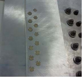
- (slide 5; also Figures 4 and 5) This photograph shows some mechanical fasteners called rivets that are typically found on aircraft fuselage (body) and wings. When engineers inspect the rivets, using a nondestructive evaluation method, they are able to create images that show if any defects are present in the metal material where you cannot see.
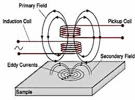
- We need to understand the science that is involved. So get out your notebooks to take some notes. (Consider providing students with printouts of the Figure 5 eddy current diagram to tape into their notebooks.) Look at this diagram of eddy current testing—a nondestructive evaluation method. When an alternating current is applied to the induction copper coil, the primary magnetic field is induced. This field generates eddy currents through a process called electromagnetic induction. As a result, a secondary field is induced in the conductive material. If a defect is present, changes in the eddy currents and magnetic field occur and the pickup coil can measure these changes. This same approach has many other applications in which highly sensitive and spatially resolved conductivity analysis can help to solve various inspection tasks.
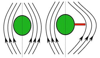
- (slide 6; also Figures 6 and 7) This next diagram shows a defect-free rivet site and a rivet site with a defect. The green dot represents a rivet. Notice how the current flows around the rivet and also flows around any flaws that exist, even when the flaws are unseen.
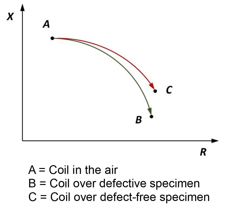
- Variations in the electrical conductivity or magnetic permeability of the object being inspected—or the presence of any flaws—cause this change in eddy current and a corresponding change in the magnetic field, the impedance, I. A difference can be measured between the primary magnetic field and the secondary field. The impedance, as measured by a probe of a defect-free specimen, is lower than that of a specimen with a defect, as illustrated in this graph (Figure 7). So this is how engineers conduct, and measure, nondestructive evaluation of airplane fuselage without taking them apart!
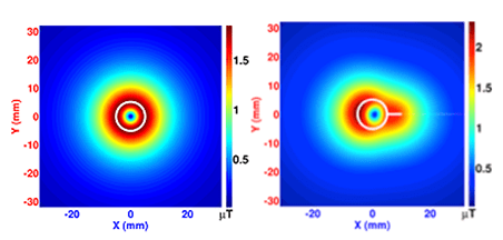
- (slide 7; also Figure 8) These colorful graphics are examples of the types of images that engineers produce in order to “see” defects and flaws.
- (slide 8; also Figures 9 and 10) Shown here, Maxwell’s equations govern the physics that we saw in Figure 5. Maxwell's equations describe how electric charges and electric currents create electric and magnetic fields. Furthermore, they describe how an electric field can generate a magnetic field, and vice versa. These equations form a system of linear equations similar to those that we have already solved, just more complex. And, they cannot be solved (analytically) by hand, like you have done already. When engineers model systems of equations virtually, they use computer programs to solve them.

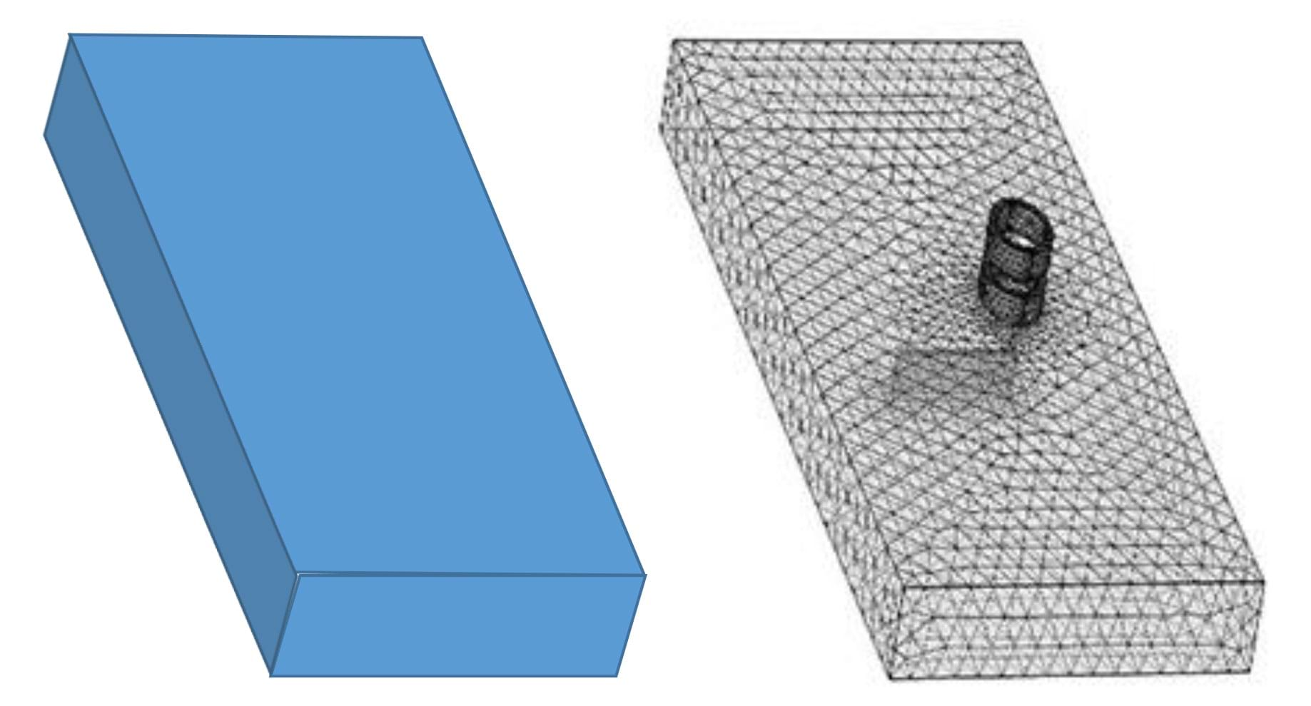
- For example, take a piece of aluminum that looks like a rectangular prism (Figure 10-left). We think of this as complex geometry and the equations are a system of complex physics equations (Maxwell’s equations; Figure 9). The finite element method, FEM, takes the complex geometry and breaks it down into millions of simpler geometries (“hat” ^ or triangle-like functions; Figure 10-right). As a result, the complex equations become millions of simpler linear equations and computers can easily solve these systems of equations, coming up with solutions that are not the exact solution but are good approximations.
- Tell students: Next, we are going to do a series of mini-activities to help you to see the physics and develop a better understanding behind what was just explained.
Part 2: Intro Activities—Connecting the Science and Mathematics (1-2 class periods)
Through this series of short experiments, or mini-activities, students become familiar with the science that is being used and make the mathematical connections. Each group participates in and rotates through six stations, with each student independently completing the Introductory Activities Worksheet as the instructor walks around the room answering questions and making sure groups stay on task.
Activity 1: Nondestructive Testing (NDT) Exploration—Students explore the nondestructive evaluation (NDE) concept by experiencing how difficult it is to determine the individual shapes of unseen objects hidden under a cover (see Figure 11). Set up this activity station with the following materials:
- 5 to 10 different shaped solids (such as a set of six wooden basic geometric solids from Amazon; alternatively, use classroom objects such as a Kleenex box, stapler and cylindrical pencil holder; alter the blank worksheet table to reflect the number of objects [currently provides for 10 items])
- a board or shallow tray with a location grid similar to a map; make grid markers visible on the edges of the board so students can see that the top left “square” of the grid is A1, the next “square” to the right is B1, etc.
- cover; use any non-see-through, lightweight material, such as a piece of cloth or fabric
- 5 to 10 marbles
- small sticky labels and a pen, to place on the cover sheet to identify the solids by number
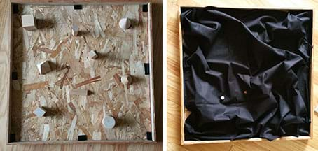
- Before students arrive, scatter the solids on the board, placing each at a grid location (such as, cube at B4, pyramid at C2, etc.). Place the cover over the board to hide the solids, leaving the grid coordinates exposed on the edges. Identify each solid “bump” by placing numbered labels (1 through 10) on the cover where they can be seen.
- During the activity, students roll marbles around the board to try to determine the solids’ shapes. Have students each independently complete the worksheet, stating everything that they can about each shape, giving coordinates and guessing the shapes as best they can.
- Expect students to discover that it is difficult to determine an exact shape without lifting the cover. Make the connection that visual inspections cannot always tell you enough about what you are inspecting.
Activity 2: Magnetic Field Exploration—Students explore the concept of magnetic fields and learn how to draw accurate magnetic field line patterns for bar magnets.
Set up this activity station with the following materials:
- bar magnet, one or more
- student magnetic field demonstrator; these thin, clear plastic slabs are filled with iron filling that line up when a magnet is placed on top, revealing magnetic field lines (such as available at Amazon)
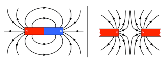
To render an accurate model of a magnetic field, students must represent the polarity of the field. Every magnetic field line has one end that is the south polarity and one end that is the north polarity. No field lines have the same polarity at both ends. By convention, physicists represent magnetic polarity by using arrows that point along the field line in the direction of the south polarity. Remind students to refer back to the posters they made earlier. Figure 12 shows the magnetic field line patterns for two common polarity situations.
Activity 3: Current Flow Exploration—Students conduct a simple experiment in which they create a current using a hand-held generator. They see the effect the current has on the compass and use the right-hand rule to sketch the created magnetic field for each direction of current flow.
Use the following materials to set up this activity station as shown in Figure 13:
- hand-held generator (such as a hand-held DC generator with 2 leads at Amazon)
- copper wire and sand paper (available at hardware stores such as Home Depot)
- compass
- Before students arrive, create a coil out of copper wire; sand the coating off of the wire at each end. Connect each wire as shown in Figure 13. Place the compass adjacent to the excitation coil. When the crank is turned clockwise, the current flows from the red (+) alligator clip to the black (-) clip. When the crank is turned counter-clockwise, the flow is from the black (-) clip to red (+) clip.
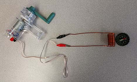
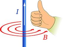
- Tell students: When we create the current, since current is literally moving charged particles, we generate magnetic fields. Once you know the direction of the current, use the right-hand rule to determine the direction of magnetic field flow. Look carefully at Figure 14 (also on the worksheet). First, point your thumb in the direction of the current. Then, curl your fingers around the wire. The direction your fingers point is the same direction as the field. Be sure to use your right hands!
Activity 4: Real-World Application of System of Equations—Students use systems of equations and apply Ohm’s law to solve a circuit problem—the circuit in Figure 15.

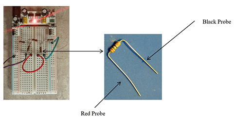
- Before students arrive, construct the Figure 15 circuit (also refer to Figure 16 and the associated activity, Applications of System of Equations: An Electronic Circuit). Use the following materials to set up this activity station as shown in Figure 16:
- breadboard setup (such as the Frentaly Small 400 Tie Point Prototype PCB Breadboard + 65 pcs jump cable wires + power supply at Amazon)
- K2 power supply (available at Amazon)
- 9V DC batter power cable barrel T-type connector (such as available at Amazon)
- 9V battery
- 5 resistors: 52.3 kOhms, 28 kOhms, 10.5 kOhms, 12.1 kOhms, 14.7 kOhms (such as from a pack of 525 at Amazon—Elegoo 17 values 1% resistor kit assortment, 0 ohm-1M ohm)
- 3-5 wires
- voltmeter
- Ti-Nspire calculators
- First, have students rewrite the equation with the given values of the resistors and voltage for the circuit. The equations needed for the analysis of the Figure 15 circuit are:
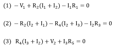
- Then have students solve the equations by hand or by using Ti-Nspire calculators. Remind them that the final units are amperes.
- Have students test the pre-built circuit. To do this, students use the voltmeter to measure the voltage across each resister and use this number to calculate the current using Ohm’s law. Let students know that this is the real electrical circuit for the previous (Figure 15) schematic diagram. The resistors are lined-up in the same way. Have them orient the resistor the same way every time and place the red probe on the left side and the black probe on the right—and then take the reading.
Activity 5: Finite Element Method (FEM) Simulation—Students run a (free, downloadable) computer program to explore a simulation of a finite element method model. (Tip: Download in advance since it may take 30-40 minutes.)
Using this software, students enter numbers (input values) and the program gives them a graph with two lines: true solution and approximate solution. Then they use the graphs to determine the best number of segments (when the approximate solution line best fits the true solution line). They select a value that forces the approximate solution to match the true solution graph, so they line up perfectly.
Activity station preparation steps:
- Prepare a computer with a python environment—a good one is anaconda.
- Type Continuum.io into a web browser.
- From Continuum.io, download Anaconda Python 2.7 for your operating system and install.
- Launch Spyder. Note that details may be slightly different, depending on your operating system.
- Once opened, click file and then open and select the FEM_Simulation.py file.
- Click the green arrow.
- Follow the prompts in the Ipython console.
- At this point, expect the prompt shown in Figure 17 to appear.
- To explore the simulation, key in a number between 10 and 400. (Note that numbers smaller than 10 or greater than 400 will not work; for numbers less than or equal to 9, greater than or equal to 1, and greater than 400, the system asks you to choose again. The number 0 exits the program.)

Part 3: Concluding Assignment—Have each group create a poster that answers the essential question: How can we investigate and measure the inside of an object or its structure if we cannot take it apart? Provide 1-2 class periods for students to create and present their posters. See the worksheet and Assessment section for poster requirements.
Associated Activities
- Applications of Systems of Equations: An Electronic Circuit - Students solve for current values when given a system of linear equations that mathematically models a circuit diagram. Then groups build electric circuits from the same schematic using breadboards, resistors and jumper wires, measuring the current flow across each resistor. They compare their mathematically derived and voltmeter-measured values and calculate percentage difference.
Lesson Closure
Albert Einstein once stated, “How can it be that mathematics, being after all a product of human thought that is independent of experience, is so admirably adapted to the objects of reality?” Connecting the mathematics that students use in the mathematics classroom to real-world applications is critical for the many students who do not see math’s relevance in their lives. It is important to facilitate a class discussion before administering the post-quiz. Have students come up with a list of questions that the lesson information and experiences have answered—or have not answered—and foster a student-driven discussion about all of them. Advise students to take notes to prepare for the post-quiz. Some example discussion questions/answers:
- Why is the finite element method and solving the systems of equations so important in the real world? (Example answer: The finite element method and systems of equations are important because they help to model potential failures in the physical objects and structures that we depend upon. Engineers use finite element method computer simulations to model potential failures as they aim to create structures and products that are safe, reliable and long-lived.)
- How is the finite element method related to the mathematics we use in class? (Example answer: The finite element model takes a set of complex equations that represents a real-life situation and through computer software simulates the situation and solves a very large set of systems of linear equations. In similar fashion, we used a set of two or more linear equations to represent a real-life situation and used systems to solve them.)
- What is nondestructive evaluation? Why is it used? (Example answer: NDE is a method of inspecting materials and physical “things” without damaging what is being inspected. For example, analyzing the condition and integrity of the materials that compose bridges, dams, bicycle frames or the human body without taking material samples, which would damage the objects/structures being examined. NDE techniques have been invented for use in engineering as well as medicine and art. For example, nondestructive testing technologies are important in determining the non-visible condition of aging infrastructure and aircraft, and in medical diagnostics, such as using sound waves and x-rays to create images of internal body structures and organs. Also see the Engineering Connection section.)
- (suitable as an assignment that students answer in a short paragraph) How does this real-world experience and its connection with mathematics and engineering impact you? (Example answer: Engineers use science and mathematics to make the physical “things” we depend on safe and reliable.)
Vocabulary/Definitions
eddy current: Loops of electrical current induced within conductors by a changing magnetic field flow in the conductors. Eddy currents flow in closed loops within conductors, in planes perpendicular to the magnetic field.
electric current: A flow of electric charge. The rate at which charge flows past a given point in an electric circuit. Measured in amperes.
electrical conductor: A material or object that allows the flow of electrical current in one or more directions.
finite element method: A numerical technique for finding approximate solutions to boundary value problems for partial differential equations. Used for structural analysis. Abbreviated as FEM. Also called finite element analysis (FEA).
inductance: The property of an electric circuit by which a changing magnetic field creates an electromotive force, or voltage.
magnetic excitation: The process of generating a magnetic field by means of an electric current.
magnetic field: A region near a magnet, electric current or moving charged particle in which a magnetic force acts on any other magnet, electric current or moving charged particle. Produced by electric currents. Dipolar in nature; has a north and a south pole; current flows from north to south. Specified by a direction and magnitude (strength).
Maxwell’s equations: A set of partial differential equations that describe how electric charges and electric currents create electric and magnetic fields.
nondestructive evaluation: A wide group of analysis techniques used to evaluate the properties of materials, components and systems without causing damage. Abbreviated as NDE. Also called nondestructive testing (NDT), nondestructive examination (NDE) and nondestructive inspection (NDI).
Ohm’s law: The current through a conductor between two points is directly proportional to the voltage across the two points.
voltage: A quantitative expression of the potential difference in charge between two points in an electrical field. Also called electromotive force. Measured in volts.
Assessment
Pre-Lesson Assessment
Pre-Quiz: Administer the three-question Pre/Post-Quiz that asks students about their knowledge of nondestructive testing, the use of finite element method (systems of equations) and real-world impacts. Administer the quiz again at lesson end. The questions are written to encourage students to verbalize what they know/have learned in a general sense and how it can impact the real world.
Post-Introduction Assessment
Worksheet: As groups work through the five mini-activities, have students individually complete the Introductory Activities Worksheet in class. Doing this series of small experiments helps to familiarize students with the science that is being used and make the mathematical connections. Review their worksheets to gauge their depth of comprehension.
Lesson Summary Assessment
Poster & Presentation: Have each group create a poster that presents their findings and answers the essential question. Than have them present their posters to the rest of the class. Students’ posters and answers reveal their depth of comprehension of the lesson topics. Require each poster to contain the following components:
- Poster title
- All group members’ names, class name and school period
- Brief explanation and diagrams that explain one of the following:
- Nondestructive evaluation (NDE) (the engineering)
- Physics, including eddy current and magnetic field (the science)
- Finite element method (the math)
- Answer to the essential question: How can we investigate and measure the inside of an object or its structure if we cannot take it apart? (Answer: Subject the object to a magnetic and/or electrical field so we can “see” the interior and measure any imperfections in the structure.)
Post-Quiz: After completion of the mini-activities and a concluding class discussion (see the Lesson Closure section), administer the Pre/Post-Quiz again. Compare students’ pre and post scores to gauge their learning gains about nondestructive testing, the use of finite element method (systems of equations) and real-world impacts.
Additional Multimedia Support
As part of presenting the Introduction/Motivation content, show students these two videos:
- Silver Bridge Disaster video (5:53 minutes) at https://www.youtube.com/watch?v=dGQfUWvP0II
- BINDT – Bridges and NDT (2:40 minutes), explains and shows bridge maintenance using nondestructive testing techniques: https://www.youtube.com/watch?v=WVLT01V5Cq4
Additional possible videos to show the class:
- Aerospace students learning about ultrasonic testing (1:50 minutes), a newscast describes how ultrasonic testing (NDE method) can detect flaws and defects in airplane structures and materials at https://www.youtube.com/watch?v=k4nIUvdbCXM
- Nondestructive testing (NDT) at TWI (14:25 minutes), informative about a few NDT techniques presented by a company that offers NDT testing, even though not the most attention-grabbing video: at https://www.youtube.com/watch?v=tlE3eK0g6vU
What Is Nondestructive Testing? by Doug Thaler, Infrastructure Preservation Corporation, posted April 30, 2016. https://www.infrastructurepc.com/single-post/2016/04/30/What-is-Non-Destructive-Testing
Subscribe
Get the inside scoop on all things Teach Engineering such as new site features, curriculum updates, video releases, and more by signing up for our newsletter!More Curriculum Like This

Students induce EMF in a coil of wire using magnetic fields. Students review the cross product with respect to magnetic force and introduce magnetic flux, Faraday's law of Induction, Lenz's law, eddy currents, motional EMF and Induced EMF.

Students are introduced to several key concepts of electronic circuits. They learn about some of the physics behind circuits, the key components in a circuit and their pervasiveness in our homes and everyday lives.
References
Adams, Eric. “How on God’s Green Earth Is the B-52 Still in Service?” Published April 19, 2016. Wired. Accessed July 2016. https://www.wired.com/2016/04/gods-green-earth-b-52-still-service/#slide-1
Circuit Symbols and Circuit Diagrams. July 2016. Lesson 4, Circuit Connections, Current Electricity, The Physics Classroom. (schematic diagram of circuit) http://www.physicsclassroom.com/class/circuits/Lesson-4/Circuit-Symbols-and-Circuit-Diagrams
Dann, James H. “Magnetic Fields.” Created February 24, 2012. CK-12 Foundation. Accessed June 21, 2016. https://www.ck12.org/physics/magnetic-field/lesson/Magnetic-Fields-PPC/?referrer=featured_content%20(open%20source%20figure%205)%20Creative%20Commons%20CC%20BY-NChttp://www.ck12.org/physics/Magnetic-Fields/lesson/Magnetic-Fields-PPC/?referrer=featured_content
Feynman, Leighton and Sands. Published 2010. The Feynman Lectures on Physics, New Millennium Edition. California Institute of Technology. Accessed June 29, 2016. http://www.feynmanlectures.info/
Karpenko, Oleksii, Safdernejad, Seyed, Dib, Gerges, Udpa, Lalita, Udpa, Satish and Tamburrino, Antonello. Published online April 2015. Image processing algorithms for automated analysis of GMR data from inspection of multilayer structures. AIP Conference Proceedings, vol. 1650, issue 1, pp. 1697-1706. http://aip.scitation.org/doi/abs/10.1063/1.4914791
Lei, Naiguang. Published 2014. Fast Solver for Large Scale Eddy Current Non-destructive Evaluation Problems. Dissertation, Michigan State University, pp. 1-22.
“Nondestructive testing.” Last updated September 18, 2017. Wikipedia, The Free Encyclopedia. Accessed September 21, 2017. https://en.wikipedia.org/w/index.php?title=Nondestructive_testing&oldid=801282069
Odenwald, Sten. Space Math @ NASA. Goddard Space Flight Center, National Aeronautics and Space Administration. Accessed June 29, 2016. http://spacemath.gsfc.nasa.gov/SpaceMath.html
Suragus Sensors and Instruments. (graphic of nondestructive eddy-current technology) Accessed July 2016. https://www.suragus.com/en/technology/
Copyright
© 2017 by Regents of the University of Colorado; original © 2016 Michigan State UniversityContributors
Marianne Livezey; Oleksii Karpenko; Anton EfremovSupporting Program
Smart Sensors and Sensing Systems RET, College of Engineering, Michigan State UniversityAcknowledgements
This curriculum was developed through the Smart Sensors and Sensing Systems research experience for teachers under National Science Foundation RET grant no. CNS 1609339. However, these contents do not necessarily represent the policies of the NSF, and you should not assume endorsement by the federal government.
Last modified: April 19, 2023


User Comments & Tips