
Quick Look
Grade Level: 12 (11-12)
Time Required: 1 hours 45 minutes
(can be split into two 50-minute sessions)
Lesson Dependency:
Subject Areas: Physics
NGSS Performance Expectations:

| HS-PS3-5 |
Quick Look

Summary
To begin, students use the associated activity to induce EMF in a coil of wire using magnetic fields. Then, demonstrations on eddy currents show how a magnetic field can slow magnets just as eddy currents are used to slow large trains. Then students observe a demonstration in which a loop "jumps" because of a changing magnetic field. Finally, a lecture reviews the cross product with respect to magnetic force and introduces magnetic flux, Faraday's law of Induction, Lenz's law, eddy currents, motional EMF and Induced EMF.Engineering Connection
Engineers must find ways to reduce the effects of eddy currents in an MRI machine as energy dissipation must be carefully controlled for personnel safety. Currently, engineers use the physics behind eddy currents to create brakes for large trains, a concept shown in lesson demos 1 and 2. During the train's braking, the metal wheels are exposed to a magnetic field from an electromagnet creating eddy currents in the wheels. The eddy currents meet resistance throughout the wheel and dissipate their energy as heat, which essentially slows down the wheels and causes the train to stop. In this lesson's homework assessment, students apply the concept of magnetic flux to a changing circuit, as electrical engineers would.
Learning Objectives
After this lesson, students should be able to:
- Describe the effects of moving a current loop in and out of a magnetic field.
- Calculate the magnetic flux through a solenoid or loop of current.
- Use Farraday's law to calculate electric and magnetic fields.
- Describe eddy currents and their properties.
- Calculate the EMF formed from changing a magnetic field
Educational Standards
Each Teach Engineering lesson or activity is correlated to one or more K-12 science,
technology, engineering or math (STEM) educational standards.
All 100,000+ K-12 STEM standards covered in Teach Engineering are collected, maintained and packaged by the Achievement Standards Network (ASN),
a project of D2L (www.achievementstandards.org).
In the ASN, standards are hierarchically structured: first by source; e.g., by state; within source by type; e.g., science or mathematics;
within type by subtype, then by grade, etc.
Each Teach Engineering lesson or activity is correlated to one or more K-12 science, technology, engineering or math (STEM) educational standards.
All 100,000+ K-12 STEM standards covered in Teach Engineering are collected, maintained and packaged by the Achievement Standards Network (ASN), a project of D2L (www.achievementstandards.org).
In the ASN, standards are hierarchically structured: first by source; e.g., by state; within source by type; e.g., science or mathematics; within type by subtype, then by grade, etc.
NGSS: Next Generation Science Standards - Science
| NGSS Performance Expectation | ||
|---|---|---|
|
HS-PS3-5. Develop and use a model of two objects interacting through electric or magnetic fields to illustrate the forces between objects and the changes in energy of the objects due to the interaction. (Grades 9 - 12) Do you agree with this alignment? |
||
| Click to view other curriculum aligned to this Performance Expectation | ||
| This lesson focuses on the following Three Dimensional Learning aspects of NGSS: | ||
| Science & Engineering Practices | Disciplinary Core Ideas | Crosscutting Concepts |
| Develop and use a model based on evidence to illustrate the relationships between systems or between components of a system. Alignment agreement: Use mathematical representations of phenomena or design solutions to describe and/or support claims and/or explanations.Alignment agreement: | When two objects interacting through a field change relative position, the energy stored in the field is changed. Alignment agreement: | Cause and effect relationships can be suggested and predicted for complex natural and human designed systems by examining what is known about smaller scale mechanisms within the system. Alignment agreement: Models (e.g., physical, mathematical, computer models) can be used to simulate systems and interactions—including energy, matter, and information flows—within and between systems at different scales.Alignment agreement: |
Common Core State Standards - Math
-
Make sense of problems and persevere in solving them.
(Grades
K -
12)
More Details
Do you agree with this alignment?
-
Rearrange formulas to highlight a quantity of interest, using the same reasoning as in solving equations.
(Grades
9 -
12)
More Details
Do you agree with this alignment?
-
Solve linear equations and inequalities in one variable, including equations with coefficients represented by letters.
(Grades
9 -
12)
More Details
Do you agree with this alignment?
-
Solve equations and inequalities in one variable
(Grades
9 -
12)
More Details
Do you agree with this alignment?
International Technology and Engineering Educators Association - Technology
-
Energy can be grouped into major forms: thermal, radiant, electrical, mechanical, chemical, nuclear, and others.
(Grades
9 -
12)
More Details
Do you agree with this alignment?
State Standards
Tennessee - Math
-
Make sense of problems and persevere in solving them.
(Grades
K -
12)
More Details
Do you agree with this alignment?
-
Solve equations and inequalities in one variable
(Grades
9 -
12)
More Details
Do you agree with this alignment?
-
Solve linear equations and inequalities in one variable, including equations with coefficients represented by letters.
(Grades
9 -
12)
More Details
Do you agree with this alignment?
-
Rearrange formulas to highlight a quantity of interest, using the same reasoning as in solving equations.
(Grades
9 -
12)
More Details
Do you agree with this alignment?
Tennessee - Science
-
Understand magnetic poles, magnetic fields, and investigate electromagnetic induction.
(Grades
9 -
12)
More Details
Do you agree with this alignment?
Worksheets and Attachments
Visit [www.teachengineering.org/lessons/view/van_mri_lesson_8] to print or download.Introduction/Motivation
We need to understand these properties of changing magnetic fields in order to solve our (MRI Safety Grand Challenge unit) challenge problem. Eddy currents play into MRI technology and many engineers are concerned about their effects on humans who undergo MRIs.
Class Demo: Eddy Currents
Objective: This fun demonstration enables students to see and feel the production of eddy currents when a permanent magnet is moved in the vicinity of a conductor.
Materials:
- 1-3 copper pipes
- 1 cylindrical magnet (small enough to drop through the copper pipe)
- 1 strong NdFeB magnet
- 1 large block of copper or aluminum*
- (optional) 1 PVC pipe
- 1 non-magnetic iron cylinder (small enough to drop through the copper pipe)
* If you do not have large blocks of copper or aluminum available, improvise with a copper heat sink from an old computer or a 75-foot roll of aluminum foil, unrolling it and folding it over 75 or more times into a thick square.
Demo 1:
Have students hold the strong magnet (the stronger the better) over the block of conducting metal. The magnet neither attracts nor repels. Try to move the magnet over the surface of the metal and feel a force slowing the motion down, which is produced by the interaction with the eddy currents formed in the metal.
Demo 2:
Drop the iron cylinder through the copper and PVC pipes to show it falling through them quickly. Then drop the magnet through the PVC pipes, which also falls unhindered. Drop the magnet through the copper pipe and note that it falls much more slowly. If you have pipes of multiple thickness, or magnetic cylinders with varying strength, show how a stronger field or thicker copper results in a slower fall. Discuss this phenomenon with students in terms of Faraday's law, and what the direction of the current in the copper pipe will be. Then explain the force on the magnet in terms of repelling currents.
In order to solve the challenge problem, we need to be able to use Farraday's law and understand Lenz's law and how eddy currents work.
Class Demo: Jumping Ring
Objective: The goal of this demonstration is to help visualize Faraday's law and Lenz's law by causing a suspended ring to suddenly "jump" forward and swing in the air due to a sudden change in magnetic field. As an extension, use this demonstration to help students understand dampened and forced oscillations. If you have an existing jumping ring demonstration, you may elect to use that instead.
Materials:
- 50 to 100 metal coat hangers
- 1 30W or higher 5V DC power supply
- 2 lab stands
- 16 gauge magnet wire, 100 ft
- 3 wires with alligator clip leads
- thread, as much as needed
- 1 small loop of copper wire (unclosed)
- 1 small loop of copper wire (soldered closed)
- 1 momentary switch

To prepare the equipment, start by clipping the long straight parts out of the metal coat hangers and tape them together in a bundle. Take the magnet wire and coil about 100 feet around one side of the bundle. Take a small piece of magnet wire and solder it together into a loop about twice the diameter of the coat hanger bundle. Take another piece of wire and bend it into a similar loop without connecting the ends. Lay the coat hanger bundle with the coil on two lab stands as shown in Figure A. Suspend the closed ring around the coiled rod from above, as in Figure A. Connect the coil to the DC power supply through the pushbutton switch. For a more dramatic effect, coil another 100 feet and connect it in parallel, but make sure that the DC supply has sufficient power. The resistance of the coil should be about 1 ohm, so 5 amps of current will flow through the coil. The low voltage used in the demo makes it safe for students to touch, explore and interact with, unlike more traditional (and more spectacular) high-voltage displays causing the ring to pop into the air.
Before demonstrating, let students inspect the apparatus and discuss the change in magnetic flux that will occur in the loop, and what direction Lenz's law will dictate that the current in the ring will then flow. Then discuss whether the current in the coil is parallel or antiparallel to the current in the loop, and what the force on the loop will therefore be. Also discuss what the force on the loop will be when the current is switched off.
It is safe for you to permit students to operate the switch, and the loop can be set into motion and stopped using the force from the induced current. If the current is applied at the right time, the force will drive the oscillation of the pendulum, which can be used to discuss driven oscillations if time permits.
After demonstrating with the closed ring, replace it with the unconnected ring and ask the class what they expect to happen. The demonstration will not work, as the piece of wire no longer creates a closed conducting loop and no current will flow.
In order to solve the challenge problem on MRI safety, we need to understand magnetic fields in matter.
Lesson Background and Concepts for Teachers
Legacy Cycle Information
This lesson fits into the research and revise phase of the legacy cycle during which students are provided with additional information enabling them to revise their initial ideas for solving the challenge. The research aspect consists of an activity on induced EMF, two demonstrations on the effects of a magnetic field, and formal lecture on magnetic flux, Faraday's law of Induction, Lenz's law, eddy currents, motional EMF and Induced EMF.
Information: Faraday's Law, Lenz's Law, and Eddy Currents
Consider a rectangular conducting loop aligned perpendicular to the page moving upward into a magnetic field pointing to the right as shown in Figure B.

By the magnetic force equation 
the free electrons in the top of the conductor will accelerate out of the page, making a conventional current in the top of the loop pointing into the page. The sides of the loop will be pinched inwards by the force. If the loop rises to the point where the bottom segment is also in the field, the free electrons in the bottom segment will also accelerate out of the page, canceling the current from the top segment.
From this, we may conclude that while the conductor is partially in the field, there will be a current through the wire loop. The amount of current depends on the strength of the field and the resistive properties of the conductor.
Notice that while the loop rises into the field, the number of magnetic field lines passing through the loop is increasing. Also notice that the current produced will create its own magnetic field in the opposite direction of the uniform field. Even though a current is being set up in the wire, the magnetic force is not doing any work, but simply changing the direction of the motion of the electrons in the conducting loop.
If the loop starts to rise above the field, so that the top segment is no longer in the field, the magnetic force on the electrons produces a current in the opposite direction. In this case, the number of magnetic field lines passing through the loop is decreasing, and the current creates its own magnetic field in the same direction of the static field.
In either case, note that:
- Current is produced when the amount of magnetic field through the loop is changing.
- If the amount of field through the loop is increasing, the produced current creates a field that lessens the total field through the loop (opposes the increase).
- If the amount of field through the loop is decreasing, the produced current creates a field and makes the total field through the loop greater (opposes the decrease).
Now, one can make an interesting experiment by leaving the current loop steady and instead moving the source of the field. In this case, the electrons are not moving, but the magnetic field is. If you perform this experiment, note the same currents that you get if you move the loop of wire. This can only be reconciled with the magnetic force equation if you consider v to be the relative velocity of the electrons with respect to the field, which makes sense as only the relative velocity really matters in any other aspect of Newtonian physics.
One interesting observation to make is that in either case, the same three conclusions can be reached:
- Current is produced when the amount of magnetic field through the loop is changing.
- If the amount of field through the loop is increasing, the produced current creates a field that lessens the total field through the loop (opposes the increase).
- If the amount of field through the loop is decreasing, the produced current creates a field and makes the total field through the loop greater (opposes the decrease).
In the 1830s, Michael Faraday and Joseph Henry conducted a variety of experiments moving loops through magnetic fields and no matter how they moved the objects, the above three conclusions applied. In fact, one may just as well ask what happens if a magnetic field is simply increased or decreased and neither object moves?
If this experiment is performed, the conclusion is the same! However, in this case the magnetic force cannot be responsible for the current, as the magnetic force does not do any work. To explain this phenomenon, Faraday postulated that a changing magnetic field produced an electric field, and it was this "induced" electric field that propels the electrons around the loop.
To better explain this phenomenon mathematically, we need to formalize the concept of the magnetic field passing through an area enclosed by a loop.
Magnetic Flux


If the area that we are interested is curved, or the magnetic field is not uniform, we need to cut the area into many infinitesimally small planes and sum up, or integrate, the flux over all the tiny planes, that is, more generally,

The standard unit for magnetic flux is the Weber, where 
Example:
A tightly wound solenoid that is 30 cm long with a radius of 2 cm and has 5,000 turns per meter is placed in a uniform magnetic field of 5500 Gauss tilted at a 30-degree angle from the axis of the solenoid (see Figure D). Find the magnetic flux through the solenoid.

Solution:
If we consider a single turn of the solenoid, it has an area of 

Given a length L for the solenoid, this is a total of nL loops, so the magnetic flux through all of the loops is

Note that we are approximating this solenoid as an ideal solenoid; that is, we treat each loop as being entirely flat.
Faraday's Law of Induction
Now that we have a well-defined mathematical notion of the field passing through the loop, we can write down an equation for the electric field produced. Conceptually, Faraday's law states that the total field circling around the loop is equal to the negative of the change in the magnetic field, that is

This equation may look unwieldy, but you might note that if you integrate the electric field along a path the result is the change in potential energy. Since going around the loop indicates a positive change in potential, we will use the term "EMF" for this potential just as is done for a battery:

The electric field produced is a bit different that the electric fields that one may experience in electrostatics. Specifically, the field does not begin or end at an electric charge, instead going around in a circle just as the magnetic field does. Note also that this law does not assume the presence of a conductor, even if no wire, a field will still be generated.
If an electron circles around this field, the electron gains kinetic energy as it moves with the field lines. When the electron arrives back at its original position it will have a greater velocity than before. If a charged particle was to continually circle around this loop, it would gain more energy each time, so this induced field is not conservative!
The electric fields produced by static charges are conservative, that is, a particle coming back to the same place will return to the same potential and kinetic energy. With a changing magnetic field the electric field is nonconservative, so charged particles may experience a gain in total energy. Where is this energy coming from? Well, whatever is responsible for changing the magnetic field must be producing currents to create the field in the first place, and so that agent must be the one adding energy to the system.
Example:
A tightly wound solenoid that is 30 cm long with a radius of 2 cm and has 5000 turns per meter is placed in a uniform magnetic field which is initially zero but is increasing at a constant rate of 500 Gauss per second tilted at a 30 degree angle from the axis of the solenoid. The solenoid is connected to form a closed circuit and is made of 30 gauge copper wire, which has a resistance of 0.339 ohms per meter. Find the current through the solenoid.
Solution:
This is the same solenoid that we saw in the previous example, Figure D. The flux at a given time must then be:

Then


The negative sign indicates the direction, but it is a bit unclear which direction we are talking about, and we will discuss this in the next section.
The total resistance in the solenoid can be found by determining the length. There are nL loops with each loop having a circumference of


By Ohm's law,

This is a fairly small current, and note that the total power delivered is  (0.0816) = 0.104mW")
This is a very small amount of power. If we wanted to get more energy in the circuit, we need to either make the area enclosed larger with a wider field, or change the field more quickly.
To generate an induced current in practice, one often creates a static field, and turns a loop of wire around in the field. Although the field will not change, the changing angle means the flux through the loop will change, and so there will be induced current. The current generated will be alternating current, as it will flow one direction and then the other as the loop turns around. You might ask who is doing the work to generate the power, and the answer is you (the person turning the loop). If you do not feel like turning the crank to generate the power, find a waterfall to turn the wheel for you!
One thing remains to be discussed, and that is which way the current flows in the first place. The answer is the same as when we induce a current by moving the loop through a field, the current produced is in the direction that would create a field opposing the change in flux. This is called Lenz's law.
Lenz's Law
The current induced by a change in flux is in the direction that would produce a magnetic field that opposes the change in flux.
Eddy Currents
Although we have been only considering a loop of wire, there will be an induced electric field around any imagined loop in space by a changing magnetic field. In the case of empty space or an insulator, the effect of the field will not be the motion of any macroscopic quantity of free charge. However, in a solid conductor the free charge will move in swirling currents around the induced field. This current will lead to joule heating of the conductor, which will dissipate energy in the form of heat.

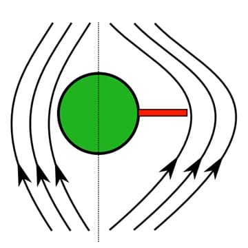
To see where this energy comes from, imagine that you are increasing the magnetic flux in a solid conductor by bringing an electromagnet (a current loop) towards the conductor as shown in Figure E. As the loop approaches, the magnetic flux induces an eddy current in the conductor that opposes the change in flux. To do this, it must produce a magnetic field in the opposite direction as the electromagnet, which means that the eddy current must be flowing in the opposite direction. As we have seen before, opposing currents repel, so there will be a force slowing the approaching magnet. So you will need to do work to keep the magnet moving towards the conductor, which is where the energy dissipated in the eddy current comes from.
Motional EMF and Induced EMF
No matter what the cause, if the magnetic flux through a conducting loop changes, an EMF is produced in accordance with Faraday's law and Lenz's law. This change in flux could be due to the strengthening of a magnetic field, or due to the loop moving into a magnetic field.
If the loop is moving into the field, the EMF is called motional EMF.
If the magnetic field itself is changing in magnitude, the EMF is called induced EMF. Refer to the Induced EMF in a Coil of Wire activity to have students experience this hands-on.
Either way, we can always find the magnitude of the EMF by the equation:
Associated Activities
- Induced EMF in a Coil of Wire - Students induce an EMF in a coil of wire using magnetic fields.
Assessment
Homework: Have students complete the Changing Fields Homework questions as a take-home assignment. Review their answers to assess their progress in comprehending the concepts of magnetic flux and induced EMF.
Subscribe
Get the inside scoop on all things Teach Engineering such as new site features, curriculum updates, video releases, and more by signing up for our newsletter!More Curriculum Like This

Students are introduced to the effects of magnetic fields in matter addressing permanent magnets, diamagnetism, paramagnetism, ferromagnetism and magnetization.

Students learn about nondestructive testing, the use of the finite element method (systems of equations) and real-world impacts, and then conduct mini-activities to apply Maxwell’s equations, generate currents, create magnetic fields and solve a system of equations. They see the value of NDE and FEM...
A class demo introduces students to the force between two current carrying loops, comparing the attraction and repulsion between the loops to that between two magnets. After a lecture on Ampere's law (including some sample cases and problems), students begin to use the concepts to calculate the magn...

In this lesson about solenoids, students learn how to calculate the magnetic field along the axis of a solenoid and then complete an activity exploring the magnetic field of a metal slinky. Solenoids form the basis for the magnets of MRIs. Exploring the properties of this solenoid helps students und...

Copyright
© 2013 by Regents of the University of Colorado; original © 2006 Vanderbilt UniversityContributors
Eric AppeltSupporting Program
VU Bioengineering RET Program, School of Engineering, Vanderbilt UniversityAcknowledgements
The contents of this digital library curriculum were developed under National Science Foundation RET grant nos. 0338092 and 0742871. However, these contents do not necessarily represent the policies of the NSF, and you should not assume endorsement by the federal government.
Last modified: May 10, 2022
User Comments & Tips