Quick Look
Grade Level: 9 (9-11)
Time Required: 45 minutes
Expendable Cost/Group: US $9.50 The activity also uses some non-expendable items like needles and hot glue guns; see the Materials List.
Group Size: 1
Activity Dependency: None
Subject Areas: Physical Science, Physics, Science and Technology
NGSS Performance Expectations:

| HS-PS3-3 |
Summary
Students’ background understanding of electricity and circuit-building is reinforced as they create wearable, light-up e-textile pins. They also tap their creative and artistic abilities as they plan and produce attractive end product “wearables.” Using fabric, LED lights, conductive thread (made of stainless steel) and small battery packs, students design and fabricate their own unique light-up pins. This involves putting together the circuitry so the sewn-in LEDs light up. Connecting electronics with stitching instead of soldering gives students a unique and tangible understanding of how electrical circuits operate.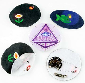
Engineering Connection
Electrical engineers play an important role in developing the countless pieces of technology we use in our daily lives. Engineers design the electrical circuits and batteries that are inside these everyday devices and appliances. Engineers must take seriously the responsibility to design circuits that work safely and dependably, which requires them to have an excellent understanding of electricity and the physics behind circuits.
Learning Objectives
After this activity, students should be able to:
- Explain the basic concepts of electricity that are necessary to fabricate a product that requires a circuit.
- Connect and build a working circuit using positive and negative traces.
- Demonstrate basic sewing skills.
Educational Standards
Each TeachEngineering lesson or activity is correlated to one or more K-12 science,
technology, engineering or math (STEM) educational standards.
All 100,000+ K-12 STEM standards covered in TeachEngineering are collected, maintained and packaged by the Achievement Standards Network (ASN),
a project of D2L (www.achievementstandards.org).
In the ASN, standards are hierarchically structured: first by source; e.g., by state; within source by type; e.g., science or mathematics;
within type by subtype, then by grade, etc.
Each TeachEngineering lesson or activity is correlated to one or more K-12 science, technology, engineering or math (STEM) educational standards.
All 100,000+ K-12 STEM standards covered in TeachEngineering are collected, maintained and packaged by the Achievement Standards Network (ASN), a project of D2L (www.achievementstandards.org).
In the ASN, standards are hierarchically structured: first by source; e.g., by state; within source by type; e.g., science or mathematics; within type by subtype, then by grade, etc.
NGSS: Next Generation Science Standards - Science
-
…and "electrical energy" may mean energy stored in a battery or energy transmitted by electric currents.
(Grades 9 - 12)
More Details
Do you agree with this alignment?
| NGSS Performance Expectation | ||
|---|---|---|
|
HS-PS3-3. Design, build, and refine a device that works within given constraints to convert one form of energy into another form of energy. (Grades 9 - 12) Do you agree with this alignment? |
||
| Click to view other curriculum aligned to this Performance Expectation | ||
| This activity focuses on the following Three Dimensional Learning aspects of NGSS: | ||
| Science & Engineering Practices | Disciplinary Core Ideas | Crosscutting Concepts |
| Design, evaluate, and/or refine a solution to a complex real-world problem, based on scientific knowledge, student-generated sources of evidence, prioritized criteria, and tradeoff considerations. Alignment agreement: | At the macroscopic scale, energy manifests itself in multiple ways, such as in motion, sound, light, and thermal energy. Alignment agreement: Although energy cannot be destroyed, it can be converted to less useful forms—for example, to thermal energy in the surrounding environment.Alignment agreement: Criteria and constraints also include satisfying any requirements set by society, such as taking issues of risk mitigation into account, and they should be quantified to the extent possible and stated in such a way that one can tell if a given design meets them.Alignment agreement: | Energy cannot be created or destroyed—it only moves between one place and another place, between objects and/or fields, or between systems. Alignment agreement: Modern civilization depends on major technological systems. Engineers continuously modify these technological systems by applying scientific knowledge and engineering design practices to increase benefits while decreasing costs and risks.Alignment agreement: |
International Technology and Engineering Educators Association - Technology
-
Students will develop an understanding of the characteristics and scope of technology.
(Grades
K -
12)
More Details
Do you agree with this alignment?
-
Students will develop an understanding of the role of troubleshooting, research and development, invention and innovation, and experimentation in problem solving.
(Grades
K -
12)
More Details
Do you agree with this alignment?
Materials List
Each student needs:
- 1 (or 2) LilyPad rainbow LEDs, such as from this set of seven LEDs in six colors from SparkFun at https://www.sparkfun.com/products/13903
- LilyPad coin cell battery holder, switched, 20 mm; such as from SparkFun at https://www.sparkfun.com/products/13883
- 3V 20-mm coin cell battery; such as CR2032 from SparkFun at https://www.sparkfun.com/products/338
- sewing needle, such as from this set of five needles from SparkFun at https://www.sparkfun.com/products/10405
- 1 pin back (see Figure 6), available at craft stores
- Pre-Activity Safety Quiz, one per student
- Sew What?! Instructions Sheet and/or Instructions Placemat, one per group
- Post-Activity Comprehension Quiz, one per student
To share with the entire class:
- conductive thread, 2+ feet per student; such as 30-ft stainless steel thread bobbin from SparkFun at https://www.sparkfun.com/products/10867
- thin fabric (like muslin) to make the pins; ~3 x 3-inch piece per pin; the fabric color and pattern can also vary, as long as the fabric is thin enough for an LED light to shine through; pin shape and size can vary at the discretion of the teacher/students, as long as the 20-mm battery holder and pin fit on the back; see the Fabric Pin Templates-Color and Fabric Pin Templates-B&W for printable patterns
- felt sheets; each pin needs a piece of felt cut to the same size as it’s thin fabric front
- assorted items and craft supplies for decorating fabric, such as markers, pens, glitter glue, fabric stamps, sequins, paint, buttons, beads
- scissors
- hot glue gun and hot glue sticks
- (optional) clear nail polish, to seal any fraying fabric
Worksheets and Attachments
Visit [www.teachengineering.org/activities/view/spfun_artpins_activity1] to print or download.Pre-Req Knowledge
It is highly recommended that students have thorough background knowledge about how electricity and circuits work since this activity does not explain electricity or circuits, but reinforces students’ existing understanding of electricity by applying it to the creation of LED pins. See the Additional Multimedia Support section for some background resources. In addition, it is helpful if students are able to hand sew using needle and thread.
Introduction/Motivation
What would life would be like without cell phones? Without computers? Or without televisions and electronic games? All of these devices—and all pieces of technology, for that matter!—have something in common: They require a source of electricity and circuitry in order to function!
Electrical engineers are the people who design the circuits inside all these devices, products and appliances. They must determine the best source of electricity for each circuit they design. For example, rechargeable batteries might be the power source that makes the most sense for cell phones, whereas wall outlets might be the most-efficient and logical power source for kitchen appliances.
Above all, electrical engineers must make sure that their designs are practical, functional, reliable and safe. Sometimes new products come to market and do not perform as intended or have flaws in their designs. Remember the exploding Samsung Galaxy Note 7 smartphone? That doesn’t happen very often because of all the careful planning and pre-release testing that goes into new products.
In this activity, you will act as if you are as electrical engineers who are designing wearable, light-up pins that require battery-powered circuits. It is up to you to create designs that are both practical and functional—but don’t worry—these pins won’t explode!
Procedure
Background
Depending on students’ prior knowledge about pertinent physics, electricity and circuits concepts, it may be useful to spend time going over some of these concepts before introducing this activity. Refer to the Additional Multimedia Support section for some useful resources.
Before the Activity
- Make activity planning decisions: What type of fabric to provide to students? Will they create their own designs or will you provide printable patterns? Will fabric printing be required? Will you provide students with one LED for each pin, or two (more complicated)? Consider pairing up students so they can help each other through the process. Consider introducing the activity several days in advance in order to give students the chance to gather their own fabric if they feel inclined to be that creative.
- Depending on student age, arrange to have some adult assistants in the classroom to operate the glue guns, guided by students telling them where to place glue and what to glue together.
- If desired, use the printable patterns, Fabric Pin Templates-B&W and Fabric Pin Templates-Color
- Make copies of the Pre-Activity Safety Quiz and Post-Activity Comprehension Quiz, one each per student, and the Sew What?! Instructions Sheet and/or Instructions Placemat, for each group.
- Gather materials and verify that electronic equipment is in working order. If possible, have enough materials so that each student can make at least one light-up pin.
- Bring students up-to-speed with a background understanding of electricity and/or circuits.
With the Students
- Present to the class the Introduction/Motivation content. Explain that the plan for the day is to design and create one (or more) LED pin each using LED lights, mini circuits, and conductive thread.
- Review with the class the safety hazards associated with the project (refer to the Safety Issues section and the Pre-Activity Safety Quiz Answers) and then administer the pre-activity quiz.
- Hand out the supplies, including the instructions sheet and/or placemat for student reference while connecting the circuits and fabricating the pins.
- Cut Pin Template, Design & Decorate: Give students time to design and create the fronts of their pins, which are made of thin fabric. This is a time for students to be creative and decide where in the design to incorporate the (one or two) LED that will shine through the thin fabric.
- Minimum size requirement: Mention that pin designs must be large enough to fit the 20-mm coin cell battery holder and a safety pin on the back.
- Patterns or free form: Either provide pre-printed pin patterns or let students create their own designs (size, shape) that accommodate the batteries and pin backs.
- Decoration: Have students use markers, pens, glitter glue and other craft supplies to draw and color the pin designs on thin fabric.
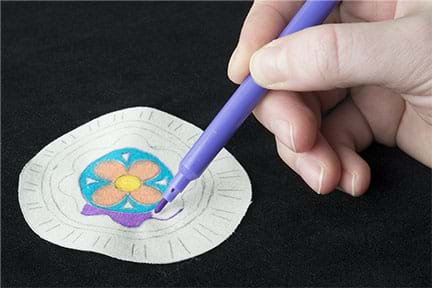
- Underneath the front of the pin, a layer of felt is necessary to attach the battery, circuit and LEDs. So have students each cut out a piece of felt that is of similar size and shape as their thin-fabric pin fronts.
- Place Components: Use hot glue to position the technology components before the sewing step. Point out that the pin fabrication is somewhat like a layered sandwich and many of the various components must line up just right in layers on top of each other. Key steps:
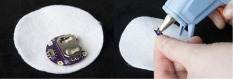
- On one side of the felt piece, use a small dot of hot glue on the back of a battery holder to glue it to the felt (see Figure 2). Make sure that the on/off switch is upright, and not on the glued side! Also, DO NOT cover the holes with glue, since they must remain unclogged for later sewing onto the felt using the conductive thread (the glue is just to tack it in place to make the sewing step easier). Also, DO NOT add the battery yet.
- On the other side of the felt piece, which is the side that will be in contact with the front fabric, place the LED light(s) near, but not on top of, the battery holder. Make sure that the (+) and (-) symbols align with the symbols on top of the battery holder. Also make sure that each LED aligns with the intended pin designs on the front fabric. Then glue the LED board(s) in place, but DO NOT cover the holes.
- Thread the Needle: Tell the students: We will be sewing paths with conductive thread for the electricity to travel from the battery pack to illuminate the LED light; these are called traces. Doing this connects the positive (+) sides of the components together, and then we’ll do the same for the negative (-) components. Essentially, we are “sewing a circuit” using conductive thread, which is made from stainless steel.
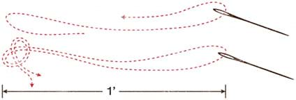
- Students each thread their needles with 2 feet of conductive thread.
- Then pull the thread through the eye and double it up. Pull the end that’s threaded through the eye so it meets up evenly with the other end of the thread. Then knot together those two tail ends (see Figure 3). This leaves you with a one-foot-long double-threaded needle, ready to sew.
- Sew Positive Trace: Next, students complete the following steps:
- On your battery holder, find the hole marked with a (+) symbol closest to the LED board on the other side of the felt. Push the needle up through the hole and the felt, then to the outside of the hole. This creates a stitch that holds the battery holder down and makes an electrical connection between the conductive thread and the metal around the hole. Repeat three times to make a secure connection (see Figure 4).
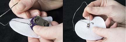
- Then, using a straight stitch, follow your path to the next positive hole on the LED apparatus. Loop around the positive (+) hole three or four times to make a secure electrical connection. Once finished at the LED, tie a knot in the thread to secure its stitching to the felt. Trim away excess thread. (See Figure 5.)
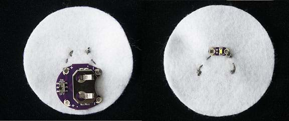
- Sew Negative Trace: Next, students tie a knot in the remaining thread on the needle, as done initially, or get a new piece of conductive thread, if necessary. Connect the negative (-) side of the battery holder to the negative side of the LED board, using the same technique used for sewing the positive trace.
- Test and Troubleshoot the Circuit: Insert the coin cell battery into the battery holder with the positive side facing up (marked with a +). Turn ON the battery holder switch to see if the LED shines bright! If the LED is not lighting up or is dim, refer to the Troubleshooting Tips section.
- Finishing Touches: Once the circuit is working:
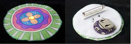
- Use hot glue to attach the decorated thin-fabric pin front to the felt layer. Before gluing, be sure the LED is lined up with the design as intended (see Figure 6).
- Turn over the pin and hot glue a pin back to the same side of the felt where the battery holder is attached (see Figure 6). Then the project is complete! Show off your wearable, light-up art pin!
- Conclude by administering the post-activity quiz, as described in the Assessment section.
Vocabulary/Definitions
conductive thread: Thread spun of stainless steel (or silver-coated nylon) that carries current like wires so that it can be used to create circuits that are flexible and require no soldering and thus are suitable for textile-based projects that use embedded electronics. Conductive thread tends to be more “twisty,” and so more difficult to sew with than non-conductive (regular) thread.
e-textiles: Clothing or accessories that include electrical components such as LEDs.
LED: An abbreviation for light-emitting diode, which is a type of semiconductor called a diode that converts electrical energy into light.
short circuit: An electrical circuit that permits a current to travel along an unintended path with no/low electrical impedance, usually resulting from the accidental contact of components that diverts the current.
trace: A physical pathway that permits conductive electricity to travel between electronic components.
Assessment
Pre-Activity Assessment
Pre-Quiz: After presenting the Introduction/Motivation content, review with the class the safety hazards associated with the project, such as the use of needles and thread, hot glue, and batteries. Then administer the three-question Pre-Activity Safety Quiz. Alternatively, give students the quiz first, and then review the answers as a class. Or conduct the quiz as an interactive discussion. Refer to the Safety Issues section and the Pre-Activity Safety Quiz Answers.
Activity Embedded Assessment
Monitor Design: As students work through the project, circulate the room to monitor their progress and answer any questions and help with any troubleshooting.
Post-Activity Assessment
Post-Quiz: At activity end, administer the three-question Post-Activity Comprehension Quiz. Review students’ answers and examine their finished pins to gauge their depth of understanding.
Investigating Questions
- What might happen if the positive (+) end of the battery pack was connected to the negative (-) end of the LED, and vice versa?
- How could we change this design to attach multiple LEDs to the pin? (Answer: See SparkFun’s extensive instructions for how to add more than one LED to a circuit.)
Safety Issues
- Working with needles creates the obvious risk of skin pricks and pokes, but also keep needles well away from eyes. The same goes for the sharp pin backs.
- Hot glue guns attain high temperatures and can burn skin that touches the hot part of the gun or any hot glue. Depending on student age, you may want to limit glue gun use to adults, with students guiding them on where to place glue and what to glue together.
- It is important that batteries are NOT inserted into their battery packs until all positive and negative traces are completed. Though unlikely, electrical injury, such as shocks, could occur.
Troubleshooting Tips
- If fabric frays at the pin edges, use clear nail polish to seal the threads.
- If students have trouble threading the needles, use a needle threader or a needle with a larger eye. Just be sure to avoid using a need that is too big for the holes provided on the LilyPad components.
- If a circuit is not lighting up (or is dim), try a new battery and make sure that the project is completely switched “ON.”
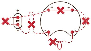
- Check the sewing for any loose conductive thread or ends that may be touching other threads or electronic components—all situations that might cause a short circuit. It pays to practice tidy stitching to keep the conductive thread from traveling to places where it shouldn’t. See Figure 7 for examples of incorrectly sewn (wired) circuitry.
- Check to make sure that the LED is in good working condition by replacing the LED bulb.
- If you suspect the circuit connection is the issue, get additional troubleshooting tips at SparkFun’s Lighting Up a Basic Circuit experiment page for e-textiles circuits.
Activity Extensions
Move on to more advanced e-textiles projects that involve more complicated circuits and art. For example, see SparkFun’s multiple LED circuits version of this activity that incorporates more than one LED in a circuit.
Activity Scaling
- For lower grades, use just one LED per pin and have student pairs work together on one pin. Focus less on the electrical circuit portion of the project and more on the art design portion so that students have a fun and successful STEM technology and art experience.
- For higher grades, see the Activity Extensions section for more involved projects. Challenge students to come up with designs that require more complex circuits and tracers, and use multiple LEDs.
Additional Multimedia Support
Some helpful background information tutorials to introduce students to electricity concepts:
Subscribe
Get the inside scoop on all things Teach Engineering such as new site features, curriculum updates, video releases, and more by signing up for our newsletter!More Curriculum Like This

Students are introduced to several key concepts of electronic circuits. They learn about some of the physics behind circuits, the key components in a circuit and their pervasiveness in our homes and everyday lives.

Students learn about current electricity and necessary conditions for the existence of an electric current. Students construct a simple electric circuit and a galvanic cell to help them understand voltage, current and resistance.

Students explore the composition and practical application of parallel circuitry, compared to series circuitry. Students design and build parallel circuits and investigate their characteristics, and apply Ohm's law.

Students are introduced to the technology of flexible circuits, some applications and the photolithography fabrication process. They are challenged to determine if the fabrication process results in a change in the circuit dimensions since, as circuits get smaller and smaller (nano-circuits), this c...
References
Activity adapted from SparkFun’s e-Textile Art Pin activity at https://learn.sparkfun.com/resources/86.
“Circuits.” TeachEngineering. Accessed December 29, 2016. https://www.teachengineering.org/lessons/view/cub_housing_lesson02
“Completing the Circuit.” TeachEngineering. Accessed December 29, 2016. https://www.teachengineering.org/activities/view/cub_electricity_lesson03_activity1
“One Path.” TeachEngineering. Accessed January 04, 2016. https://www.teachengineering.org/lessons/view/cub_electricity_lesson05
Copyright
© 2017 by Regents of the University of Colorado; original © 2014 SparkFun EducationContributors
Angela Sheehan; Emma BiesiadaSupporting Program
SparkFun EducationLast modified: August 8, 2025


User Comments & Tips