Quick Look
Grade Level: 7 (6-9)
Time Required: 45 minutes
Lesson Dependency: None
Subject Areas: Science and Technology
NGSS Performance Expectations:

| MS-PS4-2 |
Summary
Filtering is the process of removing or separating the unwanted part of a mixture. In signal processing, filtering is specifically used to remove or extract part of a signal, and this can be accomplished using an analog circuit or a digital device (such as a computer). In this lesson, students learn the impact filtering can have on different types of signals, the concepts of frequency and spectrum, and the connections these topics have to real-world signals such as musical signals. Students also learn the roles that these concepts play in designing different types of filters. The lesson content prepares students for the associated activity in which they use an online demo and a variety of filters to identify the message in a distress signal heavily corrupted by noise.Engineering Connection
In electrical engineering, filters play a dominant role in speech, image and video processing. The concept of filtering also has a variety of applications in other types of engineering beyond electrical. In chemistry, membranes are used to block impurities while letting other materials pass through. Filters also play an important role in optics; they are used to alter the colors of light by blocking certain ranges of wavelengths. In addition, filters have applications for different purposes in the areas of mechanical engineering, geophysics and petroleum engineering.
Learning Objectives
After this lesson, students should be able to:
- Describe how filters process different kinds of signals.
- Explain the concept of frequency.
- Illustrate how to extract different frequency components of a signal using different types of filters.
Educational Standards
Each TeachEngineering lesson or activity is correlated to one or more K-12 science,
technology, engineering or math (STEM) educational standards.
All 100,000+ K-12 STEM standards covered in TeachEngineering are collected, maintained and packaged by the Achievement Standards Network (ASN),
a project of D2L (www.achievementstandards.org).
In the ASN, standards are hierarchically structured: first by source; e.g., by state; within source by type; e.g., science or mathematics;
within type by subtype, then by grade, etc.
Each TeachEngineering lesson or activity is correlated to one or more K-12 science, technology, engineering or math (STEM) educational standards.
All 100,000+ K-12 STEM standards covered in TeachEngineering are collected, maintained and packaged by the Achievement Standards Network (ASN), a project of D2L (www.achievementstandards.org).
In the ASN, standards are hierarchically structured: first by source; e.g., by state; within source by type; e.g., science or mathematics; within type by subtype, then by grade, etc.
NGSS: Next Generation Science Standards - Science
| NGSS Performance Expectation | ||
|---|---|---|
|
MS-PS4-2. Develop and use a model to describe that waves are reflected, absorbed, or transmitted through various materials. (Grades 6 - 8) Do you agree with this alignment? |
||
| Click to view other curriculum aligned to this Performance Expectation | ||
| This lesson focuses on the following Three Dimensional Learning aspects of NGSS: | ||
| Science & Engineering Practices | Disciplinary Core Ideas | Crosscutting Concepts |
| Develop and use a model to describe phenomena. Alignment agreement: | A sound wave needs a medium through which it is transmitted. Alignment agreement: When light shines on an object, it is reflected, absorbed, or transmitted through the object, depending on the object's material and the frequency (color) of the light.Alignment agreement: The path that light travels can be traced as straight lines, except at surfaces between different transparent materials (e.g., air and water, air and glass) where the light path bends.Alignment agreement: A wave model of light is useful for explaining brightness, color, and the frequency-dependent bending of light at a surface between media.Alignment agreement: However, because light can travel through space, it cannot be a matter wave, like sound or water waves.Alignment agreement: | Structures can be designed to serve particular functions by taking into account properties of different materials, and how materials can be shaped and used. Alignment agreement: |
International Technology and Engineering Educators Association - Technology
-
Information and communication systems allow information to be transferred from human to human, human to machine, and machine to human.
(Grades
6 -
8)
More Details
Do you agree with this alignment?
State Standards
Colorado - Science
-
Recognize that waves such as electromagnetic, sound, seismic, and water have common characteristics and unique properties
(Grade
8)
More Details
Do you agree with this alignment?
-
Compare and contrast different types of waves
(Grade
8)
More Details
Do you agree with this alignment?
-
Describe the relationship between pitch and frequency in sound
(Grade
8)
More Details
Do you agree with this alignment?
Worksheets and Attachments
Visit [www.teachengineering.org/lessons/view/csm_filtering_lesson01] to print or download.Pre-Req Knowledge
Exposure to different types of daily life signals, such as audio signals and images. A familiarity with the concept of frequency or pitch is helpful, but not necessarily required.
Introduction/Motivation
(Be ready to show the Filtering Presentation, a PowerPoint® file, to the class.)
Today we are going to learn a basic operation called filtering, which is used in a variety of disciplines, especially in the electrical engineering field of signal processing. Can anyone name a filter they know of? (Expected possible answers: Water filter, air filter, coffee filter, etc.) Let's talk about a water filter because what happens when we use a water filter is similar to what happens when we filter signals (show slide 2, which is the same as Figure 1). What is the purpose of a water filter? (Answer: A water filter removes impurities from the water so the water is clean enough to drink.) 
Another example is an air filter, which you might find in your house or in a car (show slide 3, which is also Figure 2). The purpose of an air filter is to stop dirty particles such as dust from passing through so that cleaner air comes out the other side. The photographs on this slide show an air filter used in a rooftop air conditioning unit and an air filter—a very dirty one—from a military vehicle in Afghanistan.
From these two examples, what is the common task that filters accomplish? (Listen to student answers.) The common task that filters accomplish is the removal of impurities from the raw components. This is exactly the underlying principle of filtering: separating out what we don't want to get what we do want.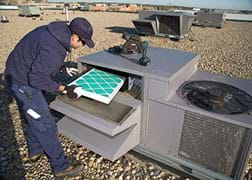
In engineering, especially electrical engineering, we send and receive information in the form of signals. Can anyone give an example of a signal they have seen or heard? (A wide range of possible answers include speech signals to cellphone and television signals.) A signal carries information from one place to another. For example, an image is a common type of signal that conveys a lot of information; as the saying goes, "a picture is worth a thousand words." Images are sent back and forth between different places all the time. In this NASA image of a galaxy (show slide 4, which is also Figure 3), the light that was captured in the image had to travel a great distance through space to get to Earth so that researchers at NASA could study it. An image like this one can tell astronomers many different things about a specific part of the universe such as the locations of stars and their sizes. 
When images, or any other signals, are sent places, they can be altered or contaminated by information that is not part of the original signal. This contamination is called "noise" and is an unwanted side effect of sending and receiving signals. Noise can come from a variety of sources:
- Noise can be created when other, unwanted signals get combined with the signal we want. For example, suppose you are at a football game trying to have a conversation with the person next to you. Your ears receive the signal you want (your friend's voice) plus many other sounds that are not of interest. Or, suppose you are trying to make a phone call while standing near a large power line. The power line's electromagnetic (radio) waves might interfere with the circuits in your phone and the radio signals that your phone sends to the cell tower.
- Noise can also be introduced by the sensor used to receive a signal. Microphones, digital cameras, thermometers, antennas, etc., all make errors when they record signals due to random variations in the materials used to construct the sensors, limited precision in the manufacturing process, etc. People who design sensors try to ensure these errors are as small as possible, but sometimes it is difficult, especially when measuring very weak signals such as recording an extremely soft sound, taking a photograph in very low light (or with high magnification), or receiving a radio signal from very far away.
Noise is the component of a received signal that we do not want because it can make it difficult to extract the information we do want. Noise is also somewhat random and unpredictable; we don't know precisely what errors will be included in a received signal.
What would be a good way to get rid of noise? (Answer: Filters!) We want to exploit the concept of filters to reduce the impact of the noise on signals so we can get the information we want.
(Show slide 5, which is also Figure 4, and slide 6) On the top of this diagram, we see a signal (also called a "waveform") that has been corrupted by noise. Such a waveform might represent the voltage signal coming out of a microphone that gets processed by an electrical circuit when we speak into a cell phone. This recorded signal contains errors introduced by the physical limitations of the microphone since the original (noise-free) signal coming into the microphone was very smooth. A filter could be designed to remove the noise in this signal and produce a smooth waveform like the one shown on the bottom of this diagram.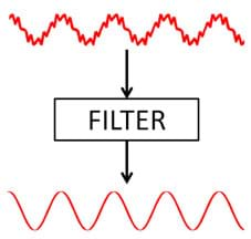
Filtering has many real-world applications ranging from noise-canceling headphones (show slide 7, which is the same as Figure 5) to improving image quality. When an unwanted external waveform enters the microphone of a headphone, a filter within the headphone detects the waveform and produces an opposite waveform to cancel out the noise. This filtering technology is useful for listening to music in loud environments such as on airplanes.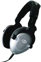
In addition to canceling noise from sound signals, filters can be used to remove noise from images (show slide 8, which is the same as Figure 6.) Take a look at this example of noise removal using filtering. Imagine that you take a photograph, but your camera is set to the wrong exposure and what you see is noisy, like the picture on the left. Filtering can help remove the noise and improve the quality of the image so that you can see the details, like the picture on the right. Students can lead their own effort to help filter out noise with the hands-on experience Filtering: Removing Noise from a Distress Signal activity.
Lesson Background and Concepts for Teachers
(Use the 29-slide Filtering Presentation, a PowerPoint® file, to present the lesson to students, starting with the Introduction/Motivation section and continuing with the content provided below.)
From the examples, we have seen the important role that filters play in engineering, especially in electrical engineering. Now, let's learn how to design filters and change the components of signals. In order to talk more concretely about how filters work, we must first talk about the concepts of frequency and spectrum
Frequency
Some waveforms exhibit a periodic behavior in which they repeat certain patterns over time. Roughly speaking, frequency is a term that describes how many times a waveform repeats a certain pattern within a certain amount of time. The standard measure of frequency is hertz (Hz), which counts the number of times a repetition occurs in 1 second (Hz = cycles per second). (Show slide 9, which is the same as Figure 7.) Look at this graphical illustration of frequency. The red waveform takes a long time to repeat itself, while the pink waveform repeats itself much more frequently in a given length of time. This means that the pink waveform has a higher frequency than the red one.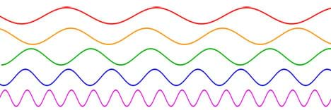
Many real world phenomena have close connections with frequency (show slide 10). For example, each key on a piano has its own note, which corresponds to a certain frequency at which the corresponding wire in the piano vibrates when the key is struck. (Show slide 11, same as Figure 8.) In this diagram, the waveform on the left in red shows middle C, which has a frequency of 261.626 Hz. Middle A, shown on the right in blue, has a frequency of 440 Hz. This agrees with our auditory sensation that the pitches of the musical notes on a piano increase as we move to the right on the keyboard.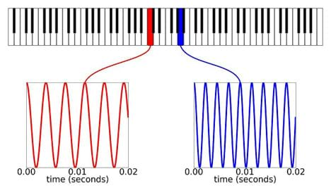
Spectrum
Plenty of real-world signals are not periodic, that is, they do not have repeating features over time. Think of these signals as being comprised of a variety of different periodic components of different frequencies and different strengths. (This is the foundation of what is called the "Fourier transform," which is widely used in a variety of engineering disciplines.)
The spectrum is a graphical representation of the range and strength of the frequencies in a signal (show slide 12). The larger the amplitude at a certain frequency, the more that frequency is represented in the signal. (Show slide 13, which is the same as Figure 9.) For example, this graph shows the spectrum of a real-world signal. From the spectrum, we clearly see that the signal is mainly composed of two frequencies, which are located at approximately 500 Hz and 1100 Hz, respectively. The spectrum provides a way to visualize the frequency content of the signal. An audio recording of someone speaking with a deep voice would have most of its spectrum located at low frequencies, while an audio recording of someone speaking with a high-pitched voice would have more of its spectrum located at higher frequencies. An audio recording of someone playing middle A on a piano would have a strong spike located at 440 Hz.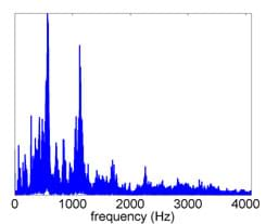
Another great example of a spectrum is a rainbow. (Show slide 14, also Figure 10.) If we shine a white light through a prism, we can separate the light into different colors that compose that light. Each color corresponds to a different frequency of the electromagnetic wave that our eyes see as visible light. By using a prism in this way, we are essentially looking at the spectrum that composes the incoming light. 
This same idea is used in the design of traffic lights (show slide 15). For a red traffic light, the glass in front of the light bulb is acting like a filter, only permitting the frequency corresponding to red light to pass through and blocking the frequencies of other colors.
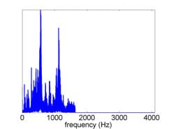
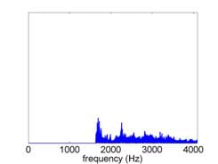
(slide 16) Similar to how traffic lights work, many filters act by keeping some frequencies and blocking others. Different types of filters exist based on diverse applications. Table 1 summarizes four well-known filters in electrical engineering, and indicates their examples in slides 17-28 and Figures 11-18.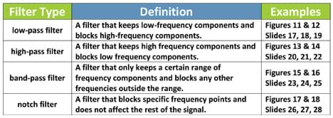
Low-pass filter: Show students the slides and figures for an original spectrum before low-pass filtering (slides 17-18; Figure 11) and the spectrum after low-pass filtering (slide 19; Figure 12).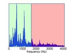
High-pass filter: Show students the slides and figures for an original spectrum before high-pass filtering (slides 20-21; Figure 13) and the spectrum after high-pass filtering (slide 22; Figure 14).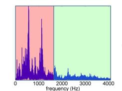
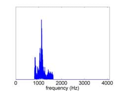
Band-pass filter: Show students the slides and figures for an original spectrum before band-pass filtering (slides 23-24; Figure 15) and the spectrum after band-pass filtering (slide 25; Figure 16).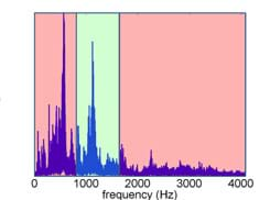
Notch filter: Show students the slides and figures for an original spectrum before notch filtering (slides 26-27; Figure 17) and the spectrum after notch filtering (slide 28; Figure 18).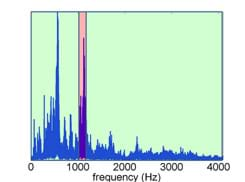
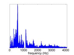
In some cases, it can be helpful to use multiple filters simultaneously to remove the noise in signals. For example, a high-pass filter could be used first to remove low-frequency noise in a signal, and then a notch filter could be applied to remove a noise component within a narrow part of the high-freque
Associated Activities
- Filtering: Removing Noise from a Distress Signal - In a hands-on experience, students analyze a signal that has been heavily corrupted by noise. They interactively choose the types of filters provided at an online demo website in order to remove noise and identify the words in a distress signal.
Vocabulary/Definitions
band-pass filter: A filter that only keeps a certain range of frequency components and blocks any other frequencies outside the range.
frequency: How many times a waveform repeats per second, measured in hertz. Hz = cycles per second
high-pass filter: A filter that keeps high-frequency components and blocks low-frequency components.
low-pass filter: A filter that keeps low-frequency components and blocks high-frequency components.
noise: Any component of a signal that does not contain useful information.
notch filter: A filter that blocks specific frequency points and does not affect the rest of the signal.
signal: Any quantity that conveys information.
spectrum: A display of the range and strength of different frequencies within a signal.
waveform: A signal that travels as a wave through some medium. Examples: sound wave, electromagnetic wave, seismic wave (earthquake).
Assessment
Pre-Lesson Assessment
Questions: Before starting the lesson, get an idea of students' familiarity with pitch and signals by asking them the following questions:
- Vocally demonstrate a "high" note and a "low" note. What do you change to produce the different pitches? (Answer: High notes are high-pitched [like a long "e" sound], while low notes are deep [like a long "o" sound. Students might relax their throats or open their mouths wider to make low notes. Students might tighten up their throats/vocal cords to make higher notes.)
- How do cell phones work? How do cell phones send and receive calls and text messages? (Answer: Cell phones correspond with base stations [cell towers] using wireless radio signals.)
- Describe for me how you think radios work. What do the different channels correspond to? (Answer: Different radio stations occupy different channel frequencies. When you change the tuner [to change the station], you are selecting a different frequency range that is used by the wireless radio to carry the music signal. These frequencies are very high, but the radio receiver processes the signals so that they can be played through the speaker and heard by people.)
Lesson Summary Assessment
Lesson Questions: At lesson end, make sure students understand the concepts of frequency and spectrum, as well as the basic filter types, by asking them the following questions:
- In sound signals, how does frequency relate to pitch? (Answer: Pitch is the auditory [subjective] sensation of frequency. Our ears can distinguish high-frequency sounds from low-frequency sounds.)
- What part of a signal does a low-pass filter throw away? (Answer: A low-pass filter keeps the low frequency part of a signal and throws away the high-frequency content.)
- What type of filter would you use to keep a section of a signal in the middle of its spectrum, while discarding the noisy sections at higher and lower frequencies?(Answer: A band-pass filter.)
- For what purposes might electrical engineers use filters? (Answer: Electrical engineers design devices to process all types of signals, ranging from audio signals [sound, voice, music] to visual signals [pictures, images, videos] to radio signals. These devices include microphones, cell phones, computers, cameras, radios, etc. The filters in these devices help remove noise and separate the signal we want from other signals we don't want. Filters can also be useful in selecting the channel on a radio, so that we can listen to just one station.)
- Ask the pre-lesson assessment questions again to see if and how students' answers changed. </u
Lesson Extension Activities
Some smartphone apps are designed to detect the frequency of musical notes. Students may enjoy experimenting with these apps to learn more about the concept of frequency.
Subscribe
Get the inside scoop on all things Teach Engineering such as new site features, curriculum updates, video releases, and more by signing up for our newsletter!More Curriculum Like This

Students learn about the science and math that explain light behavior, which engineers have exploited to create sunglasses. They examine tinted and polarized lenses, learn about light polarization, transmission, reflection, intensity, attenuation, and how different mediums reduce the intensities of ...

Students learn how AM radios work through basic concepts about waves and magnetic fields. Then students learn general concepts about magnetic fields, leading into how radio waves are created and transmitted.

Students learn about sound with an introduction to the concept of frequency and how it applies to musical sounds.
Copyright
© 2015 by Regents of the University of Colorado; original © 2013 Colorado School of MinesContributors
Michael B. Wakin; Dehui Yang; Kyle R. FeasterSupporting Program
NSF CAREER Award, Department of Electrical Engineering and Computer Science, Colorado School of MinesAcknowledgements
This curriculum was developed through the spring 2013 Digital Signal Processing (EGGN481) course in the Department of Electrical Engineering and Computer Science at the Colorado School of Mines under National Science Foundation CAREER grant no. CCF 1149225 (Michael B. Wakin). However, these contents do not necessarily represent the policies of the NSF, and you should not assume endorsement by the federal government.
Last modified: June 7, 2019


User Comments & Tips