Quick Look
Grade Level: 8 (7-9)
Time Required: 15 minutes
Lesson Dependency: None
Subject Areas: Physical Science
NGSS Performance Expectations:

| MS-PS2-2 |
Summary
Students are introduced to three of the six simple machines used by many engineers: lever, pulley, and wheel-and-axle. In general, engineers use the lever to magnify the force applied to an object, the pulley to lift heavy loads over a vertical path, and the wheel-and-axle to magnify the torque applied to an object. The mechanical advantage of these machines helps determine their ability to make work easier or make work faster.Engineering Connection
Simple machines are extremely valuable to engineers since they are used to accomplish extraordinary amounts of work with ease. In particular, engineers can design a simple machine which provides a desired mechanical advantage so that work can be done (more) efficiently and effectively. Even the most complex machines designed by engineers today are a combination of one or more of the six known simple machines. The lever, pulley, and wheel-and-axle can be found in many engineered devices, such as a crowbar, crane, and bicycle.
Learning Objectives
After this lesson, students should be able to:
- Explain how the lever, pulley, and wheel-and-axle make work easier.
- Identify how the lever, pulley, and wheel-and-axle are used in many familiar engineering systems today.
- Discuss the mechanical advantage of a lever, pulley and wheel-and-axle.
Educational Standards
Each TeachEngineering lesson or activity is correlated to one or more K-12 science,
technology, engineering or math (STEM) educational standards.
All 100,000+ K-12 STEM standards covered in TeachEngineering are collected, maintained and packaged by the Achievement Standards Network (ASN),
a project of D2L (www.achievementstandards.org).
In the ASN, standards are hierarchically structured: first by source; e.g., by state; within source by type; e.g., science or mathematics;
within type by subtype, then by grade, etc.
Each TeachEngineering lesson or activity is correlated to one or more K-12 science, technology, engineering or math (STEM) educational standards.
All 100,000+ K-12 STEM standards covered in TeachEngineering are collected, maintained and packaged by the Achievement Standards Network (ASN), a project of D2L (www.achievementstandards.org).
In the ASN, standards are hierarchically structured: first by source; e.g., by state; within source by type; e.g., science or mathematics; within type by subtype, then by grade, etc.
NGSS: Next Generation Science Standards - Science
| NGSS Performance Expectation | ||
|---|---|---|
|
MS-PS2-2. Plan an investigation to provide evidence that the change in an object's motion depends on the sum of the forces on the object and the mass of the object. (Grades 6 - 8) Do you agree with this alignment? |
||
| Click to view other curriculum aligned to this Performance Expectation | ||
| This lesson focuses on the following Three Dimensional Learning aspects of NGSS: | ||
| Science & Engineering Practices | Disciplinary Core Ideas | Crosscutting Concepts |
| Science knowledge is based upon logical and conceptual connections between evidence and explanations. Alignment agreement: | The motion of an object is determined by the sum of the forces acting on it; if the total force on the object is not zero, its motion will change. The greater the mass of the object, the greater the force needed to achieve the same change in motion. For any given object, a larger force causes a larger change in motion. Alignment agreement: All positions of objects and the directions of forces and motions must be described in an arbitrarily chosen reference frame and arbitrarily chosen units of size. In order to share information with other people, these choices must also be shared.Alignment agreement: | Explanations of stability and change in natural or designed systems can be constructed by examining the changes over time and forces at different scales. Alignment agreement: |
International Technology and Engineering Educators Association - Technology
-
Explain how knowledge gained from other content areas affects the development of technological products and systems.
(Grades
6 -
8)
More Details
Do you agree with this alignment?
State Standards
Colorado - Science
-
Predict and evaluate the movement of an object by examining the forces applied to it
(Grade
8)
More Details
Do you agree with this alignment?
-
Use mathematical expressions to describe the movement of an object
(Grade
8)
More Details
Do you agree with this alignment?
Pre-Req Knowledge
Students should be familiar with the six simple machines, as discussed in Lesson 1 of this unit, The Advantage of Machines.
Introduction/Motivation
Today we are ready to learn about three more simple machines. These include the lever, pulley, and wheel-and-axle. These machines may sound unfamiliar initially, but it is likely you will recognize them when we reveal the many everyday applications, equipment, and appliances in which they are found. Although one of the six simple machines is not superior to another, each machine offers its own distinct advantages for various engineering applications. These advantages, along with how engineers use them, will be discussed in today's lesson as we study these next three exceptional machines. Following the lesson, students can employ their knowledge alongside their creativity in the hands-on associated activity Machines and Tools, Part II.
Many engineers today, especially mechanical engineers, are interested in simple machines and their ability to carry out an immense amount of work with minimal effort. To understand how this is achieved, it is necessary to recall that work is done by applying force to a load and transporting it over some distance. The more force applied and the further the load is moved, the more work is done. This idea is expressed mathematically as
We know that a specific amount of work needs to be completed for a certain task. However, nature does not specify exactly how this work may be accomplished. This enables engineers to complete the same amount of work with less force by simply moving the load over a greater distance. This tactic of making work easier is performed with simple machines such as the lever, pulley, and wheel-and-axle.
Lever
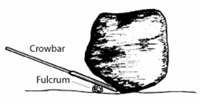
The lever is the most familiar of all the simple machines because of its plain construction and extensive use in numerous engineering devices. It merely consists of a rigid beam or rod which freely rotates about a fixed point, also referred to as the fulcrum. By positioning the fulcrum close to a heavy object and applying an effort from far away, levers can be used to lift enormous loads with ease (refer to Figure 1). The object being moved by the lever is often called the load, or output force, while the force applied to the lever is called the effort, or input force. The crowbar is a classic example of how the lever is employed to do work easier. With the crowbar, carpenters can easily extract nails from wood that would be nearly impossible and extremely inefficient without such a handy machine.
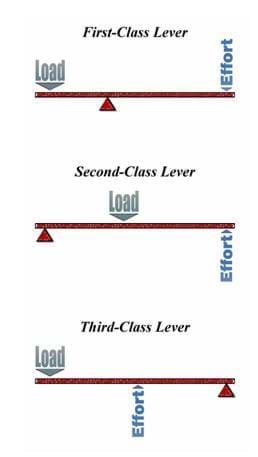
Immediately you will see that there is always a fulcrum, load and effort positioned somewhere on the lever, yet it may be difficult to notice how the position of each of these relative to one another can change the characteristics of the lever altogether. For this reason, levers are classified into three different types; called first-, second- and third-class levers (see Figure 2).
The classification of each depends on the position of the fulcrum relative to the effort and load. In a first-class lever, the fulcrum is placed between the effort and load to resemble a seesaw. Examples of this type of lever include a balance scale, crowbar, and a pair of scissors.
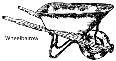
A second-class lever is when the load is placed between the fulcrum and effort. This lever type has been used in the design of many devices such as a wheelbarrow, nutcracker, bottle opener, and conventional door.
Lastly, third-class levers operate with the effort applied between the fulcrum and load. These levers can be found in tweezers, fishing rods, hammers, boat oars, and rakes.
Pulley
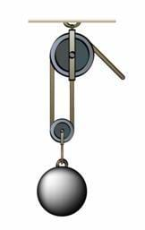
Throughout history, engineers have found the pulley to be the machine of choice when lifting heavy objects over a direct vertical path. The pulley is basically a grooved circular disk which acts to guide a rope or cable pulled around its perimeter, as illustrated in Figure 4. With a single pulley, engineers can change the direction of an applied force; such as pulling a rope down to lift a weight up. However, using a combination of pulleys in a pulley system can change both the amount and direction of the applied effort. To increase the pulley's lifting power, pulley wheels are added to a pulley system so that the effort required to lift objects vertically is largely reduced. This machine is incorporated into the design of various engineering systems such as a crane, where huge loads are manipulated with a little force supplied by a relatively small motor. Some cranes can have numerous pulley wheels and a complex array of cables so that the ability to lift heavier objects is even greater. Many other devices employ the pulley in order to benefit from its amazing potential, including an elevator, sailboat, and a basic flagpole.
Wheel-and-Axle
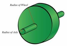
The last simple machine we are going to learn about is the wheel-and-axle, which engineers primarily use to increase a turning or rotational force. This device is composed of a circular wheel directly connected to a circular shaft or axle, and turned to rotate about a common axis (see Figure 5). From this arrangement, you may notice how the wheel and axle operates similar to that of the lever; however, it is different in the sense that it has the ability to increase a rotational force instead of a linear force. Engineers commonly refer to a rotational force as torque. In order to remain consistent with the definition of mechanical advantage, we define the wheel and axle such that the effort or input force is always applied to the wheel and the load or output force is always acting on the axle.
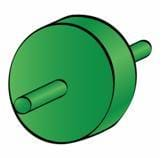
In most cases, the axle is smaller than the wheel and the applied torque is magnified by the machine; however, this configuration is not always the case. In some instances, the axle is larger than the wheel, and the input distance is increased by the machine instead of the input torque.
Examples of the wheel and axle include a screw driver, steering wheel, jet engine, mechanical gears, and even doorknobs.
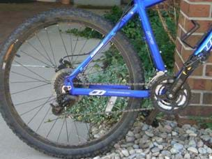
A bicycle is a great example of several simple machines like the wheel-and-axle, lever, and pulley, integrated into one device (see Figure 6). The front and back tires are wheel-and-axles, where the tires rotate around the axle in the center where the gears are fixed. The gears and chain act as a pulley and help to drive the wheel on its axle. There are several levers on a bicycle, one of which is the pedal. All three of these simple machines are necessary for a bicycle to move! As you ride your bike, your leg transfers energy to the pedal (lever), which then gets tranferred from the pedal to the chain and gears (pulley system). This energy finally gets transferred to the wheel-and-axle system (tires) and then to the ground to make the bicycle move forward!
Lesson Background and Concepts for Teachers
The mechanical advantage of a machine characterizes its ability to do work efficiently and effectively. Therefore, anytime a simple machine is considered for an appropriate engineering system, it is necessary to determine its associated mechanical advantage. In Lesson 1 of this unit, the mechanical advantage of a machine is defined as the ratio of the load (resistance the machine overcomes) to the effort (the force applied). The mechanical advantage is a way to determine how well a machine is performing. This idea can also be expressed by the general mathematical equation:
For the three simple machines in this lesson, it is important to clarify what the mechanical advantage of a machine reveals about its capabilities. If MA = 1 (Mechanical Advantage = 1), this implies the machine has no effect on alleviating work, since the output force is exactly the same as the input force. Most simple machines provide a mechanical advantage greater than 1 (MA > 1) so that work is made easier; i.e., the input force is increased, and therefore, the mechanical advantage is less than the output force.
There are some cases when it is beneficial to have a mechanical advantage less than 1. On this occasion, work is made harder by the machine since the input force is greater than the output force. This may seem contrary to the purpose of simple machines; however, the force must be reduced by the machine in order for distance to be magnified. This is sometimes very useful in certain engineering applications and surprisingly common among the three machines discussed in this lesson.
To summarize this concept, if MA < 1, distance is multiplied — work is made harder, but faster; if MA > 1, force is multiplied — work is made easier, but slower. With this information, engineers can modify the mechanical advantage of a machine in order to produce an effective, efficient, and very useful appliance.
Mechanical Advantage
Lever
The advantage of levers, which relates effort and load (or input and output force), depends on how far away each are from the fulcrum. The mechanical advantage of a lever is increased when either the effort is moved further away from the fulcrum or the load is shifted closer to the fulcrum, or both. This idea of leverage can be expressed mathematically by:
In this equation, the distance between the load and fulcrum is called the Load Arm, while the distance from the fulcrum to the effort is called the Effort Arm as shown in Figure 9.
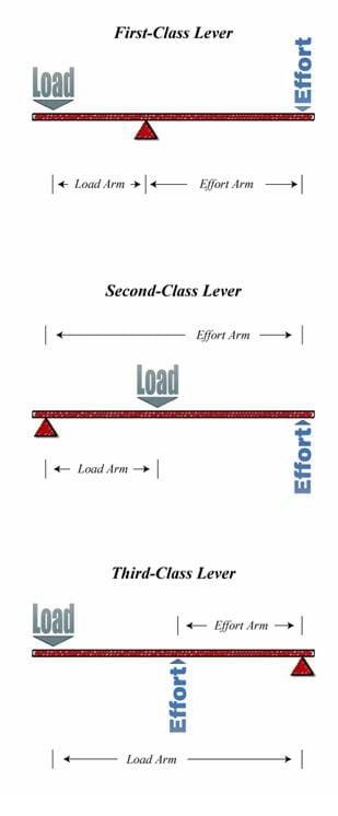
Notice that a single definition for the mechanical advantage of a lever applies to all three classes of levers. However, because of the physical arrangement of each lever type, we note that for second-class levers, MA > 1, yet for third-class levers, MA < 1. First-class levers have the unique option to magnify either the input force or the input distance (MA > 1 or MA < 1). The capabilities of these different lever types provide engineers with an array of choices during the design and selection process of a particular engineering system.
Pulley
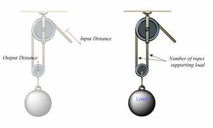
A pulley system operates on the principle that a load can be lifted easier by pulling on a rope or cable that is wrapped between a supporting structure and a rigid fixture attached to the load itself. One extremely common idea — and often a rule of thumb — for a pulley is to calculate its mechanical advantage by counting the number of pulley wheels found in a system. While this practice is generally acceptable, the method does not always provide accurate results. A more precise method for calculating the mechanical advantage of a pulley is by counting the number of ropes or cables which support the load. Then the mathematical relationship is simply expressed as:
This result may seem unrelated to the general definition of mechanical advantage; however, this machine remains in perfect agreement with the definition once the input and output distances are identified. From Figure 11, we can see how the input distance, output distance, and number of support lines are related in a pulley system. In this example, if a pulley has a mechanical advantage of 2 (MA = 2), pulling on the end of the support line with effort over a given input distance will cause the load to be raised a distance equal to half that pulled by the effort. This is true regarding all pulley combinations: the more support lines attached to the load, the more input distance required to raise the load up to a desired height. To conclude, we find that the physical geometry of a pulley system requires its mechanical advantage to always be greater than 1 and only in positive integer values; i.e., MA = 1, 2, 3, etc.
Wheel-and-Axle
Before stating the mechanical advantage of a wheel-and-axle, it is extremely important to remember that the effort is always applied to the wheel, while the load always acts to resists the turning motion of the axle. Specifically, as effort is applied to the wheel and rotated through an angle θ, geometry dictates the input distance to be the product of θ and the wheel radius. Likewise, since the axle is fastened to the wheel and turned through the same angle θ, the output distance is the product of θ and the axle radius. Then from the general definition, we see the mechanical advantage of the wheel-and-axle depends only on the radius of each, where it can be written as:
This result informs engineers how the mechanical advantage of a wheel-and-axle may be altered to provide the most efficient results in an engineering system. Typically, engineers configure the wheel-and-axle so its mechanical advantage is greater than 1 to benefit from a magnified torque, such as the case with a steering wheel. If engineers prefer the wheel-and-axle to multiply distance and thus do work faster, such as the case with a bicycle, the machine is constructed with its axle larger than the wheel, or MA < 1.
Associated Activities
- Machines and Tools, Part II - Students construct a system of pulleys to discover how its mechanical advantage can be increased and if their results agree with the calculated values.
Lesson Closure
All simple machines are characterized by their ability to provide mechanical advantage, which allows engineers to design devices to make work easier and more efficient. Although one machine is not superior to another, each machine provides its own unique and attractive capabilities which are used by engineers for numerous applications. The lever is capable of quickly increasing either force or distance; the pulley can lift enormous loads over a vertical path; and the wheel-and-axle is used to easily increase an input torque. These three simple machines, combined with the other three (inclined plane, wedge and screw), give engineers a set of extremely valuable tools to effectively carry out work.
Vocabulary/Definitions
complex machine: A machine that operates by combining two or more of the six simple machines.
lever: A simple machine consisting of a rigid beam or bar which pivots about a fixed point to move heavy loads with less effort.
mechanical advantage: The number of times a force exerted on a machine is multiplied by the machine.
pulley: A simple machine consisting of a grooved circular wheel which guides a rope, cable or chain. This machine is primarily used to lift heavy loads along a direct vertical path.
simple machine: The fundamental parts of any machine. Simple machines can exist on their own and are also sometimes hidden in the mechanical devices around you; a device which performs work by increasing or changing the direction of force, making work easier for people to do.
torque: The result of applying a linear force at the outside of a circular frame to create a turning tendency.
wheel-and-axle: A simple machine consisting two circular or cylindrical objects which are fastened together and rotate about a common axis. This machine is primarily used to magnify a torque supplied by the user.
work: The energy spent moving an object over a distance using force (W = Fd).
Assessment
Pre-Lesson Assessment
Question/Answer: Ask students the following questions and and discuss as a class:
- Work is defined as the product of force and distance. Which one of these things, force or distance, makes work harder to do? (Answer: Force. If a machine can reduce the force required to do work, it is generally easier to apply it over a longer distance.)
- Work is defined as the product of force and distance. Which one of these things, force or distance, makes work fast or slow? (Answer: Distance. If a machine can reduce the distance required to do work, it is generally faster to carryout the work, even though it is harder to do.)
Post-Introduction Assessment
Voting: Ask a true/false question and have students vote by holding thumbs up for true and thumbs down for false. Tally the votes and write the numbers on the board. Give the right answer.
- True or False: The lever has four different components. (Answer: False. The lever has three main components; the fulcrum, effort and load. These components can be arranged in three different ways and so the lever has three different classifications.)
- True or False: The lever is a better simple machine than either the pulley or wheel and axle. (Answer: False. While the lever may be a better choice for engineers in a specific design, one machine is not superior to another. Every simple machine has its own unique advantages which can be used for different engineering applications.)
Lesson Summary Assessment
Discussion Question: Solicit, integrate and summarize student responses.
- Ask students how the mechanical advantage of a machine helps engineers. Students should understand that if a machine's mechanical advantage is less than 1, the machine magnifies the input distance (work is harder but much faster). If a machine's mechanical advantage is greater than 1, the machine magnifies the input force (work is easier but slower). If MA = 1, the machine does nothing and work is the same. In other words:
If MA < 1, then work is harder, but faster
If MA > 1, then work is slower, but easier
Lesson Extension Activities
Team Competition: Organize the class into small groups of two or three students each and challenge each group to think of where in engineering systems today the lever, pulley and wheel-and-axle can be found. The group that thinks of the most machines is the winning team. To get full credit, each team must state the engineering device along with the associated simple machine. Examples: Lever: seesaw, balance scales, crowbar, wheelbarrow, nutcracker, bottle opener, tweezers, fishing rod, hammer, boat oar, rake, etc. Pulley: crane, elevator, flagpole, etc. Wheel and Axle: screwdriver, steering wheel, bicycle gears, doorknob, etc.
Complex Machines:
[Note to teacher: This extension activity is one that should be done after all six simple machines have been introduced to students through this lesson and the lesson Just Plane Simple]
A complex machine is one that operates by combining two or more simple machines together. Consider a pair of scissors. The two arms that you squeeze together are levers, while the cutting edges of the blades are sharp wedges. The scissors were a solution to a real-world problem that was made simple by breaking it down into smaller pieces. The simple machines of a lever and wedge were combined to create an engineering solution.
In groups of two, think about the following complex machines. For each complex machine, list the simple machines that have been combined and where they are found (just like the description of the scissors):
- Wheelbarrow
- Manual can opener
- Pencil sharpener
- Corkscrew
Answers:
- Wheelbarrow: The wheelbarrow itself is a 2nd class lever combined with a wheel and axle to make it roll.
- Manual can opener: The handle you rotate is a wheel and axle. The two long arms that clamp make a lever. The circular wheel that cuts the metal lid is a sharp wedge.
- Pencil sharpener: The blade that cuts and sharpens the pencil is a wedge. A screw holds the pieces together. The piece you spin is a wheel and axle.
- Corkscrew: The rotating handle at the top is a wheel and axle. The spiral metal piece that secures the cork is a screw. The sharp tip on the bottom of the spiral piece is a wedge to dig into the cork before turning. The two side arms that are pushed down are levers.
Subscribe
Get the inside scoop on all things Teach Engineering such as new site features, curriculum updates, video releases, and more by signing up for our newsletter!More Curriculum Like This

Students are introduced to the six types of simple machines — the wedge, wheel and axle, lever, inclined plane, screw, and pulley — in the context of the construction of a pyramid, gaining high-level insights into tools that have been used since ancient times and are still in use today.

This lesson introduces students to three of the six simple machines used by many engineers. These machines include the inclined plane, the wedge and the screw.

In this lesson, students learn about work as defined by physical science and see that work is made easier through the use of simple machines. Already encountering simple machines everyday, students will learn about their widespread uses in improving everyday life.

Students explore building a pyramid, learning about the simple machine called an inclined plane. They also learn about another simple machine, the screw, and how it is used as a lifting or fastening device.
References
Kahan, Peter. Motion, Forces, and Energy: Science Explorer Student Edition. Upper Saddle River, NJ: Prentice Hall, 2002.
Macaulay, David. The Way Things Work. Boston, MA: Houghton Mifflin Company, 1988.
Environment: Hand Tools for Trail Work. Las updated June 16, 2005. Federal Highway Administration, U.S. Department of Transportation. Accessed August 31, 2007. http://www.fhwa.dot.gov/environment/fspubs/05232810/page16.htm
Woods, Michael, and Mary Woods. Ancient Machines: From Wedges to Waterwheels. Minneapolis, MN: Runestone Press, 2000.
Other Related Information
Browse the NGSS Engineering-aligned Physics Curriculum hub for additional Physics and Physical Science curriculum featuring Engineering.
Copyright
© 2007 by Regents of the University of Colorado.Contributors
Jake Lewis; Malinda Schaefer Zarske; Janet YowellSupporting Program
Integrated Teaching and Learning Program, College of Engineering, University of Colorado BoulderAcknowledgements
This digital library content was developed by the Integrated Teaching and Learning Program under National Science Foundation GK-12 grant no. 0338326. However, these contents do not necessarily represent the policies of the National Science Foundation, and you should not assume endorsement by the federal government.
Last modified: January 12, 2021


User Comments & Tips