Summary
Students find and calculate the angle that light is transmitted through a holographic diffraction grating using trigonometry. After finding this angle, student teams design and build their own spectrographs, researching and designing a ground- or space-based mission using their creation. At project end, teams present their findings to the class, as if they were making an engineering conference presentation. Student must have completed the associated Building a Fancy Spectrograph activity before attempting this activity.Engineering Connection
Engineers design spectrographs to study atmospheres and surfaces of stars, planets and even components of other galaxies, as part of ground- or space-based missions (depending on the desired wavelength of study). To make a spectrograph work correctly, engineers consider many factors. They carefully measure and compute all angles. They use combinations of ray-trace computer programs, test, and computational analysis to determine the path the light takes in the spectrograph. A slight miscalculation makes instrument useless, so it is crucial to compute these angles and test them to make sure they are accurate before building a protective case to enclose the spectrograph. Engineers also explore with other engineers and scientists possible improvements to the design to create an efficient and effective instrument.
Learning Objectives
After this activity, students should be able to:
- Understand and explain that light seen through a diffraction grating shows all of the colors of that light.
- Create a spectrograph prototype.
- Design a ground- or space-based mission using the spectrograph prototype.
Educational Standards
Each TeachEngineering lesson or activity is correlated to one or more K-12 science,
technology, engineering or math (STEM) educational standards.
All 100,000+ K-12 STEM standards covered in TeachEngineering are collected, maintained and packaged by the Achievement Standards Network (ASN),
a project of D2L (www.achievementstandards.org).
In the ASN, standards are hierarchically structured: first by source; e.g., by state; within source by type; e.g., science or mathematics;
within type by subtype, then by grade, etc.
Each TeachEngineering lesson or activity is correlated to one or more K-12 science, technology, engineering or math (STEM) educational standards.
All 100,000+ K-12 STEM standards covered in TeachEngineering are collected, maintained and packaged by the Achievement Standards Network (ASN), a project of D2L (www.achievementstandards.org).
In the ASN, standards are hierarchically structured: first by source; e.g., by state; within source by type; e.g., science or mathematics; within type by subtype, then by grade, etc.
NGSS: Next Generation Science Standards - Science
| NGSS Performance Expectation | ||
|---|---|---|
|
HS-PS4-5. Communicate technical information about how some technological devices use the principles of wave behavior and wave interactions with matter to transmit and capture information and energy. (Grades 9 - 12) Do you agree with this alignment? |
||
| Click to view other curriculum aligned to this Performance Expectation | ||
| This activity focuses on the following Three Dimensional Learning aspects of NGSS: | ||
| Science & Engineering Practices | Disciplinary Core Ideas | Crosscutting Concepts |
| Communicate technical information or ideas (e.g. about phenomena and/or the process of development and the design and performance of a proposed process or system) in multiple formats (including orally, graphically, textually, and mathematically). Alignment agreement: | Solar cells are human-made devices that likewise capture the sun's energy and produce electrical energy. Alignment agreement: Information can be digitized (e.g., a picture stored as the values of an array of pixels); in this form, it can be stored reliably in computer memory and sent over long distances as a series of wave pulses.Alignment agreement: Photoelectric materials emit electrons when they absorb light of a high-enough frequency.Alignment agreement: Multiple technologies based on the understanding of waves and their interactions with matter are part of everyday experiences in the modern world (e.g., medical imaging, communications, scanners) and in scientific research. They are essential tools for producing, transmitting, and capturing signals and for storing and interpreting the information contained in them.Alignment agreement: | Systems can be designed to cause a desired effect. Alignment agreement: Science and engineering complement each other in the cycle known as research and development (R&D).Alignment agreement: Modern civilization depends on major technological systems.Alignment agreement: |
| NGSS Performance Expectation | ||
|---|---|---|
|
MS-ETS1-1. Define the criteria and constraints of a design problem with sufficient precision to ensure a successful solution, taking into account relevant scientific principles and potential impacts on people and the natural environment that may limit possible solutions. (Grades 6 - 8) Do you agree with this alignment? |
||
| Click to view other curriculum aligned to this Performance Expectation | ||
| This activity focuses on the following Three Dimensional Learning aspects of NGSS: | ||
| Science & Engineering Practices | Disciplinary Core Ideas | Crosscutting Concepts |
| Define a design problem that can be solved through the development of an object, tool, process or system and includes multiple criteria and constraints, including scientific knowledge that may limit possible solutions. Alignment agreement: | The more precisely a design task's criteria and constraints can be defined, the more likely it is that the designed solution will be successful. Specification of constraints includes consideration of scientific principles and other relevant knowledge that is likely to limit possible solutions. Alignment agreement: | All human activity draws on natural resources and has both short and long-term consequences, positive as well as negative, for the health of people and the natural environment. Alignment agreement: The uses of technologies and any limitations on their use are driven by individual or societal needs, desires, and values; by the findings of scientific research; and by differences in such factors as climate, natural resources, and economic conditions.Alignment agreement: |
Common Core State Standards - Math
-
Apply geometric methods to solve design problems (e.g., designing an object or structure to satisfy physical constraints or minimize cost; working with typographic grid systems based on ratios).
(Grades
9 -
12)
More Details
Do you agree with this alignment?
-
Use trigonometric ratios and the Pythagorean Theorem to solve right triangles in applied problems.
(Grades
9 -
12)
More Details
Do you agree with this alignment?
-
Prove the Pythagorean identity sin²(θ) + cos²(θ) = 1 and use it to find sin(θ), cos(θ), or tan(θ) given sin(θ), cos(θ), or tan(θ) and the quadrant of the angle.
(Grades
9 -
12)
More Details
Do you agree with this alignment?
International Technology and Engineering Educators Association - Technology
-
Students will develop an understanding of the attributes of design.
(Grades
K -
12)
More Details
Do you agree with this alignment?
-
Use instruments to gather data on the performance of everyday products.
(Grades
6 -
8)
More Details
Do you agree with this alignment?
-
Evaluate the design solution using conceptual, physical, and mathematical models at various intervals of the design process in order to check for proper design and to note areas where improvements are needed.
(Grades
9 -
12)
More Details
Do you agree with this alignment?
-
Apply a broad range of making skills to their design process.
(Grades
9 -
12)
More Details
Do you agree with this alignment?
State Standards
Colorado - Math
-
Use the Pythagorean identity to find sin(θ), cos(θ), or tan(θ) given sin(θ), cos(θ), or tan(θ) and the quadrant of the angle.
(Grades
9 -
12)
More Details
Do you agree with this alignment?
-
Use trigonometric ratios and the Pythagorean Theorem to solve right triangles in applied problems.
(Grades
9 -
12)
More Details
Do you agree with this alignment?
-
Apply geometric methods to solve design problems.
(Grades
9 -
12)
More Details
Do you agree with this alignment?
Colorado - Science
-
Use appropriate measurements, equations and graphs to gather, analyze, and interpret data on the quantity of energy in a system or an object
(Grades
9 -
12)
More Details
Do you agree with this alignment?
Materials List
Each group needs:
- 1 holographic diffraction grating (1,000 lines per mm or 25,400 grooves per inch)
- 1 scientific calculator
- 1 protractor or angle ruler
- 1 ruler
- Graph paper
- Butcher-block paper
- Designing a Spectroscopy Mission Worksheet, one per team
To share with the entire class:
- 4-5 large sheets of black foam core board
- 1 red or green laser pointer
- 1 white light source (incandescent light bulb, not fluorescent)
- Copies of Astronomy Today or Sky and Telescope magazines
- Internet-accessible computers, for research
Have readily available, if needed:
- X-ACTO knives
- Scissors
- Masking tape
- Duct tape
- Black paint
Materials note:
- Student teams are asked to make a materials list. Encourage them to use already-available materials found around the home or school (to minimize items that must be purchased).
- Purchase holographic diffraction gratings in sheets or card-mounted slides. For example:
- Rainbow Symphony Store, http://www.rainbowsymphony.com/
A set of 10 12-inch x 6-inch linear sheets with 500 lines per mm costs $25
A set of 50 2-inch x 2-inch linear calibrated card mounted slides with 500 lines per mm costs $20
A set of 100 2-inch x 2-inch linear calibrated card mounted slides with 500 lines per mm costs $35
Worksheets and Attachments
Visit [www.teachengineering.org/activities/view/cub_spect_activity8] to print or download.Pre-Req Knowledge
The students must have a basic understanding of trigonometry, as well as the nature of light and prisms.
Introduction/Motivation
Have you heard about scientists and engineers who discover the components of the atmosphere or surface of a far-off planet, star, comet or other astronomical body? How can they know what material(s) forms the molecules and atoms of these bodies without actually physically traveling to them? Well, sometimes, they send a spaceship to the object or use spacecraft orbiting the Earth, and other times they figure it out using instruments on the ground. In all cases, they use spectrographs to measure the atomic and molecular constituents.
A spectrograph is a device that bends incoming light to form a spectrum. The first spectrographs used photographic paper, which is paper coated with light-sensitive chemicals. Today, most spectrographs use what is called a charge-coupled device or CCD camera.
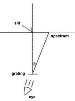
(Draw Figure 1 on the board or overhead projector.) Here is a diagram showing how a simple spectrograph works.
Light passes through the slit, making its way to the holographic diffraction grating. Once the light reaches the grating, it bends at a certain angle represented by the Greek letter theta (θ). This angle is different for every wavelength. What this means is that light hitting the diffraction grating diffracts onto a surface (or within your eye), and the position of the color is dependent on the color itself! For example, green light diffracts through the grating at a different angle than violet, etc. The color that diffracts at the biggest angle is red, and the color that has the smallest angle is violet.
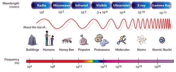
Light travels in waves. Wavelength is the distance between one peak or crest of a wave of light and the next corresponding peak or crest. Wavelength is a measure of distance and is generally shown in units of micrometers, nanometers, millimeters, centimeters and meters. As you can see from this drawing of the electromagnetic spectrum (Figure 2), every color of light has a different wavelength — which is why we are able to see a spectrum. You can also see that the spectrum includes many different types of light that we cannot see, such as x-rays or radio waves.
A diffraction grating is a surface with a series of evenly-spaced grooves. When light hits the surface, it diffracts, or bends, around the grooves at a certain angle, which is dependent upon its wavelength. Today, we use holographic diffraction gratings, which are basically thin pieces of film with a hologram of the grooves printed onto it.
Our grating has 1,000 lines per mm, meaning it has 1,000 parallel grooves in every 1 mm of the surface. In a spectrograph, if you look through the holographic grating toward the light source, the image appears at that angle in front of your eye.
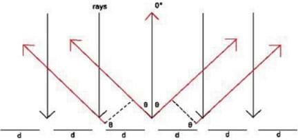
The distance between the grooves is "d." To find out the distance between the grooves if there are 1,000 grooves per millimeter, we divide the length (1 mm) by the number of grooves (1,000). This can be represented by the following equation:
where N = the number of grooves per unit length (in this case, millimeters)
From Figure 3, we see "d" is the grating spacing, and "θ" is the angle of diffraction. The dotted line represents one complete wavelength,λ. Knowing this allows us to map out where our spectrum will be located in our spectrograph.
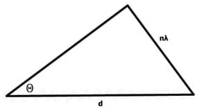
As shown in Figure 4, a triangle shows the angle at which the spectrum will appear. We find the angle θ by using the following equation:
We want to find λ, so using simple trigonometry we can see that:
where "n" is the order number. In this experiment, we will use n = 1.
Today, your team will begin to design and build a prototype of a spectrograph for a mission you design. Over the next few weeks, you will conduct research about the mission you would like to do and build a spectrograph using provided materials as well as any additional materials you request after discussing your plan with me. The mission can be something you imagine, such as sending your spectrograph to another planet, or something you do from the ground. Remember, you are constrained by the wavelengths the diffraction grating is capable of producing, so you are limited by the diffraction grating provided. You are also limited by what your eye is capable of seeing.
Procedure
Terminology Note
In creating the Spectroscopy curricular unit, the Project SPECTRA! program chose to use the term “spectrograph” (as opposed to spectroscope) for the engineering projects activities because a spectrograph is a tool used in spacecraft and modern telescopes, and Project SPECTRA! is an astronomy program. A spectrograph uses a detector, usually a CCD (a charge coupled device, similar to those used in digital cameras), to record the properties of light. Technically, in this unit, students build “spectroscopes,“ which are similar to spectrographs, however, instead of using a detector, the human eye directly observes the light within the scope or projected onto a screen. The primary difference between the two instruments is the method in which the light is detected. A spectrograph enables a person to observe light that cannot be seen with the eye (typically ultraviolet, infrared, and x-rays) because the detector records these wavelengths electronically, enabling the signals to be observed as plots or graphs. In this curricula, when students build their “space-worthy” spectrographs, we consider the students themselves to be the detectors, and leave to their instructors the option of providing students with more in-depth explanation.
Background
Establishing θ
The holographic diffraction grating used in this activity has 1,000 grooves per mm.With this number of grooves, students can only view light with wavelengths between 400 nm and 700 nm, or the visible portion of the spectrum, which also happens to be the limits of the human eye. The students calculate the grating spacing, using the following equation (Equation 1):
where "d" is the grating spacing, and "N" is the number of grooves per unit length
In this case, d = 0.001 mm, which must be converted to nanometers (nm). Make the conversion by using 1 meter is equal to 1 x 10⁹ nm, or 1 millimeter is equal to 1 x 10⁶ nm. This gives you:
The grating has a spacing of 1,000 nm, which means the distance between each groove is 1,000 nm. To solve for either wavelength or angle, use the following equation:
where "n" is the order number, "λ" is the wavelength of light, and "θ" is the diffraction angle (angle to any specific color from the center of the grating)
Since the students have already calculated d in nanometers, the wavelength should also be in nanometers. The grating produces multiple images of the spectrum because of the properties of light, and each image is given a different order number. On one side, the spectrum is labeled with positive numbers, and on the other, with negative numbers. For the purposes of this activity, and to simplify the concept, state that the order number, n, is equal to 1.
Students can choose a specific wavelength and compute the angle using Equation 2, solving for θ:
Advise students to pick one color as their central wavelength; for example, the light corresponding with the color green, 550 nm, is often a good choice (see Table 1). In reality, students can compute the angles to any wavelength. If students are ambitious, they can create fairly accurate scales for their spectrographs.

Once students know the appropriate angles associated with the grating, they can begin to establish what shape will best fit the spectrograph. To make sure the spectrum appears on a flat surface, making a triangularly-shaped box is the best option. The box requires a slit that lets in light from opposite the grating, as described in the Building a Fancy Spectrograph activity. The distance from the slit to the grating is not very important, but the angles to the edges of the spectrum are what establish the shape of the box.
Alternative Methods for Establishing θ
A few experimental methods exist for determining θ for a specific wavelength. Students could shine a flashlight through the grating, directly measuring the angle of diffraction of light for several colors as described in the Engineering Your Own Spectrograph activity. Once they have these angles, they can compute each corresponding wavelength by solving for λ using Equation 2. Unfortunately, even with a focused flashlight, the beam is fairly diffuse, which may skew measurements.
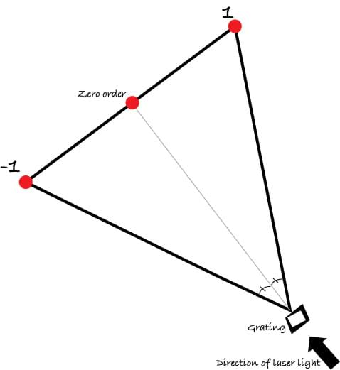
Alternatively, a more accurate method uses a laser pointer. Shine a laser pointer through the grating to measure the angle of diffraction and solve for λ. The grating produces three laser dots (spectral orders: 1, 0, -1). Direct students to ignore the one in the middle (the zero order) and measure the angle to either of the laser dots that appears at an angle to the center of the grating, as in Figure 5. They can compute the wavelength using the following equation:
Usually the laser's wavelength is printed on it, so students can compare the actual wavelength with the calculated one. Because we are using inexpensive gratings, the calculated and actual values might differ, which provides the opportunity to discuss accuracy and quality in engineering. The drawback to the laser pointer method is that only one color can be measured, but it gives some idea of where the color appears in the spectrograph. With both of these methods, make sure the grating and light source are not shifting position during the measurement by using a stand (see the Engineering Your Own Spectrograph activity for inexpensive suggestions).
Before the Activity
- Gather materials.
- Make copies of the Designing a Spectroscopy Mission Worksheet, one per team.
With the Students
- Divide the class into teams of four students each.
- Hand out the worksheets.
- Have students follow along with the activity using their worksheets.'
- Remind students that they are part of teams of NASA engineers who have been asked to create an innovative spectrograph to conduct research in the visible region of the spectrum.
Part 1: Establishing the Mission
- Student teams identify a problem related to solar system spectroscopy for the mission they will undertake.
- Students establish whether their mission is ground- or space-based, and explain why.
Part 2: Building the Spectrograph
- Student teams follow along on the worksheet to construct their own spectrograph using a grating that has 1,000 grooves per mm.
- Assist with the calculation of the grating spacing, d.
- Assist student groups with the calculation of the spectrum's position using Equation 2.
- Help students brainstorm spectrograph designs.
Part 3: Mission and Design Analysis
Student teams determine whether their spectrograph could actually achieve the mission.
Part 4: Engineering Conference Presentations
Each student team makes a10-minute class presentation, describing:
- Their mission.
- Engineering they accomplished.
- Problems they may have encountered.
- Any other topics relevant to the project.
Vocabulary/Definitions
diffraction: When light bends, as through a prism or diffraction grating.
diffraction grating: Usually a piece of film designed to act like a prism.
prototype: A first attempt or early model of a new product or creation. May be revised many times.
spectrograph: A tool that allows the components of light to be seen easily with the eye. Also: spectroscope.
spectrum: The pattern light produces as can be seen through a spectrograph. Plural: spectra.
wavelength: The distance between one peak or crest of a wave of light and the next corresponding peak or crest.
Assessment
Pre-Activity Assessment
Brainstorming: As a class, have students engage in open discussion. Remind them that in brainstorming, no idea or suggestion is "silly." All ideas should be respectfully heard. Take an uncritical position, encourage wild ideas and discourage criticism of ideas. Have students raise their hands to respond. Write their ideas on the board. Ask the students:
- Why do you think spectrographs are made by engineers?
- What are spectrographs used to determine?
Activity Embedded Assessment
Worksheet: Have student teams complete their activity worksheets; review their answers to gauge their mastery of the subject.
Post-Activity Assessment
Presentation: Have student teams present their final design prototypes, showing the math they used as well as how the spectrographs work. This may be a good opportunity for students to hone their PowerPoint skills in creating a 10-minute presentation. Ask students to elaborate on the research they conducted and the mission the spectrograph will undertake.
Safety Issues
- Never have students look directly at the Sun, and warn them not to look at the Sun.
Troubleshooting Tips
Colorblind and vision-impaired children will have difficulty with portions of this activity; students with corrective lenses will not. It is a good idea to pair colorblind students with others who can assist them with the activity.
Students may need assistance adjusting the position of the grating so that a continuous spectrum appears. If a continuous spectrum is not visible, rotate the grating 90°. Also, make sure the slit is visible through the grating. Make sure the slit does not have any light leaks or the spectrograph will not work properly.
Students may be confused that they see two spectra through the slit. The diffraction grating produces two spectra, and both are a complete spectrum of the source. Make sure students choose one or the other, but not both.
Subscribe
Get the inside scoop on all things Teach Engineering such as new site features, curriculum updates, video releases, and more by signing up for our newsletter!More Curriculum Like This

Students use simple materials to design an open spectrograph so they can calculate the angle light is bent when it passes through a holographic diffraction grating. A holographic diffraction grating acts like a prism, showing the visual components of light.

Students estimate the storage capacity of CDs and DVDs by assessing diffraction patterns of green and red laser beams.
Copyright
© 2008 by Regents of the University of Colorado.Contributors
Laboratory for Atmospheric and Space Physics, University of Colorado BoulderSupporting Program
Laboratory for Atmospheric and Space Physics (LASP), University of Colorado BoulderLast modified: January 11, 2022





User Comments & Tips