Quick Look
Summary
Students use simple materials to design an open spectrograph so they can calculate the angle light is bent when it passes through a holographic diffraction grating. A holographic diffraction grating acts like a prism, showing the visual components of light. After finding the desired angles, students use what they have learned to design their own spectrograph enclosure.Engineering Connection
Engineers design spectrographs so astronomers can study atmospheres of stars, planets and even components of far galaxies. An engineer must look at a lot of key factors to make sure a spectrograph works correctly. They must accurately measure all angles, sometimes using computers to perform the calculations. Engineers also discuss with other engineers and scientists how to make improvements to the design in order to create an instrument that is most efficient and effective.
Learning Objectives
After this activity, students should be able to:
- Design a simple experiment to measure the angle of light through a diffraction grating.
- Create a model of a basic spectrograph using the information they acquire during a light activity.
- Use the Pythagorean Theorem to size a spectrograph prototype.
Educational Standards
Each TeachEngineering lesson or activity is correlated to one or more K-12 science,
technology, engineering or math (STEM) educational standards.
All 100,000+ K-12 STEM standards covered in TeachEngineering are collected, maintained and packaged by the Achievement Standards Network (ASN),
a project of D2L (www.achievementstandards.org).
In the ASN, standards are hierarchically structured: first by source; e.g., by state; within source by type; e.g., science or mathematics;
within type by subtype, then by grade, etc.
Each TeachEngineering lesson or activity is correlated to one or more K-12 science, technology, engineering or math (STEM) educational standards.
All 100,000+ K-12 STEM standards covered in TeachEngineering are collected, maintained and packaged by the Achievement Standards Network (ASN), a project of D2L (www.achievementstandards.org).
In the ASN, standards are hierarchically structured: first by source; e.g., by state; within source by type; e.g., science or mathematics; within type by subtype, then by grade, etc.
NGSS: Next Generation Science Standards - Science
| NGSS Performance Expectation | ||
|---|---|---|
|
HS-PS4-5. Communicate technical information about how some technological devices use the principles of wave behavior and wave interactions with matter to transmit and capture information and energy. (Grades 9 - 12) Do you agree with this alignment? |
||
| Click to view other curriculum aligned to this Performance Expectation | ||
| This activity focuses on the following Three Dimensional Learning aspects of NGSS: | ||
| Science & Engineering Practices | Disciplinary Core Ideas | Crosscutting Concepts |
| Communicate technical information or ideas (e.g. about phenomena and/or the process of development and the design and performance of a proposed process or system) in multiple formats (including orally, graphically, textually, and mathematically). Alignment agreement: | Solar cells are human-made devices that likewise capture the sun's energy and produce electrical energy. Alignment agreement: Information can be digitized (e.g., a picture stored as the values of an array of pixels); in this form, it can be stored reliably in computer memory and sent over long distances as a series of wave pulses.Alignment agreement: Photoelectric materials emit electrons when they absorb light of a high-enough frequency.Alignment agreement: Multiple technologies based on the understanding of waves and their interactions with matter are part of everyday experiences in the modern world (e.g., medical imaging, communications, scanners) and in scientific research. They are essential tools for producing, transmitting, and capturing signals and for storing and interpreting the information contained in them.Alignment agreement: | Systems can be designed to cause a desired effect. Alignment agreement: Science and engineering complement each other in the cycle known as research and development (R&D).Alignment agreement: Modern civilization depends on major technological systems.Alignment agreement: |
| NGSS Performance Expectation | ||
|---|---|---|
|
MS-ETS1-1. Define the criteria and constraints of a design problem with sufficient precision to ensure a successful solution, taking into account relevant scientific principles and potential impacts on people and the natural environment that may limit possible solutions. (Grades 6 - 8) Do you agree with this alignment? |
||
| Click to view other curriculum aligned to this Performance Expectation | ||
| This activity focuses on the following Three Dimensional Learning aspects of NGSS: | ||
| Science & Engineering Practices | Disciplinary Core Ideas | Crosscutting Concepts |
| Define a design problem that can be solved through the development of an object, tool, process or system and includes multiple criteria and constraints, including scientific knowledge that may limit possible solutions. Alignment agreement: | The more precisely a design task's criteria and constraints can be defined, the more likely it is that the designed solution will be successful. Specification of constraints includes consideration of scientific principles and other relevant knowledge that is likely to limit possible solutions. Alignment agreement: | All human activity draws on natural resources and has both short and long-term consequences, positive as well as negative, for the health of people and the natural environment. Alignment agreement: The uses of technologies and any limitations on their use are driven by individual or societal needs, desires, and values; by the findings of scientific research; and by differences in such factors as climate, natural resources, and economic conditions.Alignment agreement: |
Common Core State Standards - Math
-
Draw (freehand, with ruler and protractor, and with technology) geometric shapes with given conditions. Focus on constructing triangles from three measures of angles or sides, noticing when the conditions determine a unique triangle, more than one triangle, or no triangle.
(Grade
7)
More Details
Do you agree with this alignment?
-
Apply the Pythagorean Theorem to determine unknown side lengths in right triangles in real-world and mathematical problems in two and three dimensions.
(Grade
8)
More Details
Do you agree with this alignment?
-
Apply the Pythagorean Theorem to find the distance between two points in a coordinate system.
(Grade
8)
More Details
Do you agree with this alignment?
-
Use trigonometric ratios and the Pythagorean Theorem to solve right triangles in applied problems.
(Grades
9 -
12)
More Details
Do you agree with this alignment?
International Technology and Engineering Educators Association - Technology
-
Students will develop an understanding of the attributes of design.
(Grades
K -
12)
More Details
Do you agree with this alignment?
-
Students will develop an understanding of the role of troubleshooting, research and development, invention and innovation, and experimentation in problem solving.
(Grades
K -
12)
More Details
Do you agree with this alignment?
-
Students will develop an understanding of the relationships among technologies and the connections between technology and other fields of study.
(Grades
K -
12)
More Details
Do you agree with this alignment?
-
Use instruments to gather data on the performance of everyday products.
(Grades
6 -
8)
More Details
Do you agree with this alignment?
State Standards
Colorado - Math
-
Draw (freehand, with ruler and protractor, and with technology) geometric shapes with given conditions.
(Grade
7)
More Details
Do you agree with this alignment?
-
Apply the Pythagorean Theorem to determine unknown side lengths in right triangles in real-world and mathematical problems in two and three dimensions.
(Grade
8)
More Details
Do you agree with this alignment?
-
Apply the Pythagorean Theorem to find the distance between two points in a coordinate system.
(Grade
8)
More Details
Do you agree with this alignment?
-
Use trigonometric ratios and the Pythagorean Theorem to solve right triangles in applied problems.
(Grades
9 -
12)
More Details
Do you agree with this alignment?
Colorado - Science
-
Compare and contrast different types of waves
(Grade
8)
More Details
Do you agree with this alignment?
Materials List
Each group needs:
- 1 rectangular piece of thick foam core, 25.5 x 76 cm (10 x 30-inch) and 5 mm (3/16 inch) thick
- 2 Styrofoam cups
- 1 holographic diffraction grating (1,000 lines per mm or 25,400 grooves per inch)
- 1 ruler
- 1 meter stick
- 1 protractor
- 1 X-ACTO knife
- 1 black fine point permanent marker
- 1 incandescent flashlight with focusing beam (mini mag-lights are best; LED flashlights do not work)
- Engineering Your Own Spectrograph Worksheet
To share with the entire class:
- 1 roll of masking tape
- Red, green and violet markers
- Sheets of paper, from legal- to poster-sized, for calculations and sketching
Material note: Purchase holographic diffraction gratings in sheets or on card-mounted slides; prices from Rainbow Symphony Store (2007)
http://www.rainbowsymphony.com/:
- A set of 10 12-inch x 6-inch linear sheets with 1,000 lines per mm for $25
- A set of 50 2-inch x 2-inch linear calibrated card-mounted slides with 1,000 lines per mm for $20
- A set of 100 2-inch x 2-inch linear calibrated card-mounted slides with 500 lines per mm for $35
Worksheets and Attachments
Visit [www.teachengineering.org/activities/view/cub_spect_activity7] to print or download.Pre-Req Knowledge
A basic understanding of geometry (such as triangles, Pythagorean Theorem, use of a protractor, etc.). Ability to work with sharp cutting utensils and rulers.
Introduction/Motivation
(Set up an example so students can look through a diffraction grating toward an incandescent light bulb with the overhead lights turned off and see how the light is diffracted, creating a rainbow. Make sure to use an incandescent light source.)
Today's scientists and engineers study the planets and stars around us, painting a picture of the universe we live in and are a part of. To study such faraway places, they must use creative techniques since they cannot travel to the nearest star or planet easily. The nearest planet is about 40 million kilometers away. That's about 23 million miles! To observe the properties of objects so far away, engineers develop tools such as space telescopes. Sometimes they create instruments called spectrographs that help determine what gasses make up the atmospheres of planets, stars and other objects. A spectrograph shows the colors of light that correspond with a particular gas. We call these spectral lines, and each gas has a different set of lines. A spectrograph uses a diffraction grating just like the ones we are using today. A diffraction grating acts like a prism. White light in this light bulb does not have gas around it, so we see a rainbow when we look through the diffraction grating. Light that we see in neon or florescent light bulbs show specific spectral lines, so we would not see rainbows, we would only see some colors of the rainbow.
When light enters a spectrograph, it enters through a slit and transmits through the diffraction grating. The light is transmitted at an angle, and produces the spectrum. You can see the spectrum when you hold the diffraction grating up to your eye and stand in front of the light bulb. You see rainbows off to the side, and not in the middle, because the grating produces two spectra on either side of the grating. When engineers design their spectrographs, they simply choose one or the other. When engineers begin to design a spectrograph, the first important thing they do is find the angle between the light source and one of the spectral lines. Once they find this angle, they can design a box that best fits the spectrograph. They want to make sure the light falls onto the detector in the instrument, because a detector is what collects the data from the spectrograph.
Today, imagine that you are engineers. Your team will set up an experiment so you can find the angle that the light transmits through the diffraction grating. Then you will use the Pythagorean Theorem to help you determine the length of the sides of a box that would be best for viewing the entire spectrum. Using this information, you will design your own prototype spectrograph. Lastly, you will imagine a space mission that would benefit from your spectrograph.
Procedure
Terminology Note
In creating the Spectroscopy curricular unit, the Project SPECTRA! program chose to use the term “spectrograph” (as opposed to spectroscope) for the engineering projects activities because a spectrograph is a tool used in spacecraft and modern telescopes, and Project SPECTRA! is an astronomy program. A spectrograph uses a detector, usually a CCD (a charge coupled device, similar to those used in digital cameras), to record the properties of light. Technically, in this unit, students build “spectroscopes,“ which are similar to spectrographs, however, instead of using a detector, the human eye directly observes the light within the scope or projected onto a screen. The primary difference between the two instruments is the method in which the light is detected. A spectrograph enables a person to observe light that cannot be seen with the eye (typically ultraviolet, infrared, and x-rays) because the detector records these wavelengths electronically, enabling the signals to be observed as plots or graphs. In this curricula, when students build their “space-worthy” spectrographs, we consider the students themselves to be the detectors, and leave to their instructors the option of providing students with more in-depth explanation.
Background
A spectrograph is a device that takes incoming light and transforms it into a spectrum. The earliest spectrographs used photographic paper that was coated with light-sensitive chemicals. Today, most spectrographs use a charge-coupled device or a CCD camera.
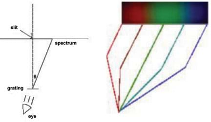
See Figure 1 for a diagram of how a simple spectrograph works. Light passes through a slit and makes its way to the holographic diffraction grating. The holographic diffraction grating used in this activity is a transmission grating with 1,000 grooves per mm. With this number of grooves, students can view light with wavelengths between 400 nm and 700 nm, or the visible portion of the spectrum. When the light reaches the holographic grating, the many grooves on the grating's surface cause the light to diffract, and separate into a rainbow — or a continuous spectrum.
Once light reaches the grating, it bends at a certain angle, represented mathematically by the Greek letter theta (θ). This angle is different for every wavelength and is determined through the equation:
λ = d * sin (θ)
where d is 1 divided by the number of lines per mm, and the Greek letter lambda (λ) is the wavelength of light
This means that light hitting the diffraction grating diffracts onto a surface, and the position of the color on that surface is dependent on the color itself! For example, green transmits through the grating at a different angle than violet. The color that diffracts at the biggest angle is red, and the color that has the smallest angle is violet. Using this knowledge, students can construct a rough scale for the grating.
Students measure the distance to the edge of the colors red and violet, and the color green. Using a protractor, they measure the angle between the incoming light and the color (see Table 1). Using the Pythagorean Theorem, they determine the length of the sides of the box optimal for viewing the entire spectrum.

For additional information, see the background information provided in the following TeachEngineering Spectroscopy unit activities: Building a Fancy Spectrograph and Using a Fancy Spectrograph.
Before the Activity
- Complete Building a Fancy Spectrograph activity so students have a good idea of how spectrographs work.
- This activity (Parts 1 and 2, below) takes about 60 minutes. Part 3 is an extension to the activity and requires another 1-2 class periods, or about more 120 minutes.
- Gather materials and cut poster board for each group.
- Print copies of the Engineering Your Own Spectrograph Worksheet, one per team.
- Place tables or desks lengthwise against a classroom wall to create a work surface.
- Set up the light activity as an example for students.
With the Students
- Divide the class into teams of two or three students each.
- Hand out student materials and the worksheets, which include instructions and diagrams for designing an open spectrograph.
- Have students follow along with the worksheet.
Part 1: Building an Open Spectrograph
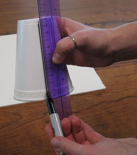
- Cut a 5cm slit in the center of the bottom of a Styrofoam cup.
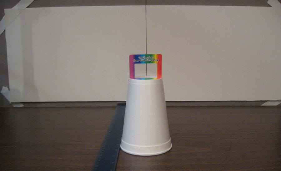
- Using a ruler as a straight edge, draw a vertical black line from the slit to the bottom of the cup (see Figure 2).
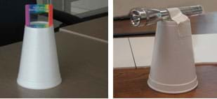
- Create a grating stand by placing the diffraction grating ½ cm into the cup (see Figure 3).
- Create a flashlight stand, by centering a small flashlight across the bottom of another Styrofoam cup. Use masking tape to loosely tape down the flashlight (see Figure 3).
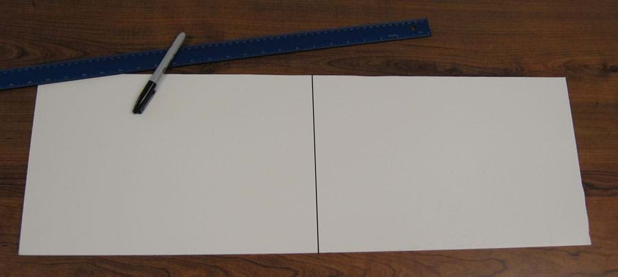
- Use a meter stick to find the center of the longer side of a foam core board. Draw a vertical line through the center, splitting the longer side into two halves (see Figure 4).
- Tape the foam board on the wall adjacent to a table, leaving enough room for a meter stick to fit underneath. This becomes your background screen (see Figure 5).
- Place the grating stand in front of the screen so that the center of the grating lines up with the central line on the screen (see Figure 5).
- Place the meter stick on the table perpendicular to the screen. Align the zero centimeter line with the front of the screen and the edge of the meter stick against the Styrofoam cup (see Figure 5). Using masking tape, secure the meter stick to the table at each end so that it does not shift.
- Turn on and then focus the flashlight so it makes a small, bright beam.
- Place the flashlight stand directly behind the grating stand facing the screen. Rest the head of the flashlight on the grating stand so the beam of light travels directly through the center of the grating (see Figure 6).
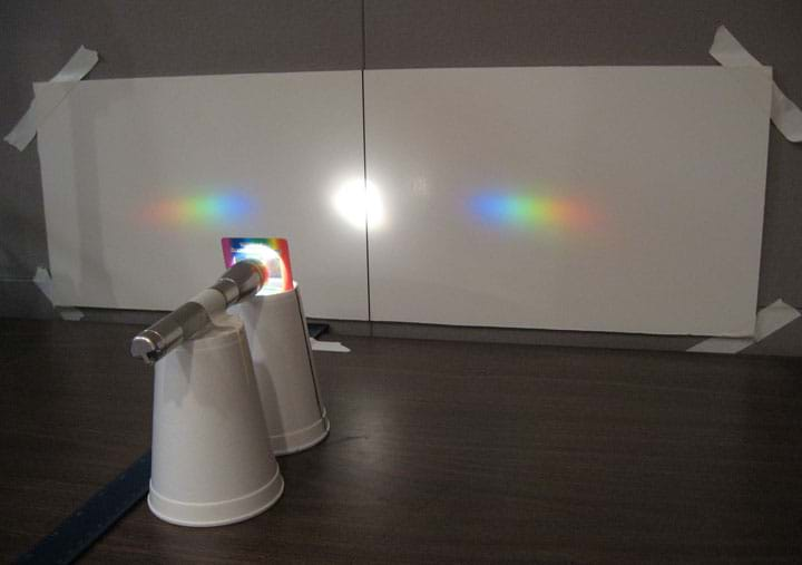
- Slide the two stands backward and forward along the meter stick until your spectra are clear and bright. As long as the spectra are on the screen, you can place the stands anywhere along the meter stick.
- Choose either the spectrum on the right OR left to make your measurements.
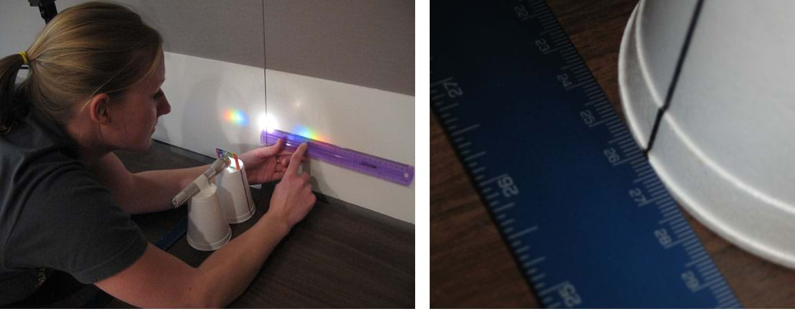
- Measure the distance from the grating and the screen by reading the meter stick where it lines up with the black line on the cup (see Figure 7). Record this distance.
- Measure the distances from the centerline on the screen to the very edge of the red and violet light. Record these distances.
- Choose a point in the green area of the light, and measure and record the distance (see Figure 7).
- Using the recorded measurements, draw a right triangle on a sheet of paper. Use the distance from the grating to the screen, and each of the measured distances to the colors. Mark the location of each of the colors with an X, and connect the apex of the triangle with each X as shown in Figure 8.
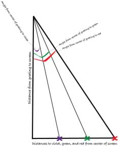
- Measure and record the angles to each color using a protractor.
- Using the Pythagorean Theorem and a calculator, determine the hypotenuse lengths for the violet and red triangles. Measure them with a ruler to confirm the lengths.
Part 2: Designing an Open Spectrograph
- Have students use the angles to the colors in the spectrum from the open spectrograph to design an enclosed spectrograph with their group.
- Begin by having students answer the questions on the worksheet and present their ideas to the class.
- Next, have them brainstorm ideas for designs of a box to enclose their prototype spectrograph.
- Conclude by leading a class discussion about missions that could use their spectrographs (see the Activity Assessment section) or continue the activity during the next class period by having students build their designs, as described below.
Part 3: Building the Spectrograph Enclosure (optional)
- (Optional: This section requires an extra 1-2 class periods or about 120 more minutes.) To extend this activity, have students build the box they designed for their spectrograph using the measurements from the activity and the knowledge gained from the Building a Fancy Spectrograph activity.
- To continue acting as engineers, have students gather the materials needed to make their group's spectrograph design. Have them prepare a materials list for the teacher to buy, or limit materials to found/recycled materials available from around the house or school.
- Have students keep a record of how much the items cost. Estimate cost when necessary.
- After building the spectrograph enclosures, have each team present theirs to the class along with a description of their missions and final cost analyses.
Vocabulary/Definitions
apex: The usually pointed end of an object; the tip.
diffraction: When light bends, as through a prism or diffraction grating.
diffraction grating: Usually a piece of film designed to act like a prism.
incandescent light bulb: A standard light bulb as found in most households.
prototype: A first attempt or early model of a new product or creation. May be revised many times.
Pythagorean Theorem: A mathematical theorem that the square of the length of the hypotenuse (C) of a right triangle is equal to the sum of the squares of the lengths of the other two sides. C2 = A2 + B2
Spectrograph: A tool that allows the components of light to be seen easily with the eye. Also: spectroscope.
Spectrum: The pattern light produces as can be seen through a spectrograph. Plural: spectra.
Assessment
Pre-Activity Assessment
Brainstorming: When making a spectrograph, engineers brainstorm different ideas to make the spectrograph correctly. They study the properties of light. Today, imagine that you are engineers and brainstorm about the following questions:
- What do you know about light?
- How does a spectrum form?
Activity Embedded Assessment
Class Discussion: Have students discuss missions that used spectrographs or spectrometers. What information did the spectrograph or spectrometer help to find out? If time permits, have students conduct Internet research on missions that use spectrographs.
Post-Activity Assessment
Designing a Mission: Following along with the activity worksheet, have students create an imaginary mission to launch their spectrograph into space. They should consider if the mission is ground- or space-based, mission goals, their spectrograph limitations, as well as size or weight restrictions, and mission cost. Students should demonstrate critical thought about the questions, even if the answers are not based on research.
Engineering Presentation: Many engineers make presentations to show their ideas and designs for a client's desired product. Have student teams create presentations and explain to the rest of the class how their prototype spectrographs work. Provide a light source so students can look through each spectrograph. Allow time after each presentation for questions. Make note of these questions and address any conceptual misunderstandings at the end of the presentations. Have student teams create missions that are perfect for their new spectrographs. Have the students use their imaginations, making either realistic or non-realistic missions.
Safety Issues
- Alert students to safe handling procedures for using X-ACTO knives.
- Never have students look directly at the Sun, and warn them not to look at the Sun.
Troubleshooting Tips
Colorblind and vision-impaired children will have difficulty with portions of this activity; students with corrective lenses will not. Pair colorblind students with others who can assist them with the activity.
Students may be confused that they see two spectra through the slit. The diffraction grating produces two spectra, and both are a complete spectrum of the source. Make sure students choose one or the other to measure, but not both.
The values for red, violet and green vary from group to group because the "edge of the red," etc. is not a concrete definition — it depends on where the students perceive this to be. Students may also be choosing a green color that is more blue or yellow as well. As long as the values for the angles are somewhere in the correct range, the answers are accurate (see table 1).
When the students design an enclosed spectrograph, they will design a box that is similar to "Building a Fancy Spectrograph" in which the light comes through a slit, and the student looks through the grating. In this format, the image forms in the eye, and is not a projection.
Activity Extensions
Part 3 of the Procedure section is an optional activity extension, requiring an additional 1-2 class periods or about 120 more minutes.
Subscribe
Get the inside scoop on all things Teach Engineering such as new site features, curriculum updates, video releases, and more by signing up for our newsletter!More Curriculum Like This

Students find and calculate the angle that light is transmitted through a holographic diffraction grating using trigonometry. After finding this angle, student teams design and build their own spectrographs, researching and designing a ground- or space-based mission using their creation.

Students create and decorate their own spectrographs using simple materials and holographic diffraction gratings. A holographic diffraction grating acts like a prism, showing the visual components of light.
Copyright
© 2007 by Regents of the University of Colorado.Contributors
Nathanael BoltSupporting Program
Laboratory for Atmospheric and Space Physics (LASP), University of Colorado BoulderAcknowledgements
The contents of this digital library curriculum were developed under a grant from the Fund for the Improvement of Postsecondary Education (FIPSE), U.S. Department of Education, and National Science Foundation GK-12 grant no 0338326. However, these contents do not necessarily represent the policies of the Department of Education or National Science Foundation, and you should not assume endorsement by the federal government.
Last modified: February 25, 2020





User Comments & Tips