Quick Look
Grade Level: 9 (9-12)
Time Required: 3 hours 30 minutes
(This activity is split into two parts, ~60 minutes for Part 1: Planning Phase; ~120 minutes for Part 2: Building Phase)
Expendable Cost/Group: US $3.00 Note: This activity uses an optional non-expendable (re-usable) LEGO® MINDSTORMS® ultrasonic sensor and software; see the Materials List for details.
Group Size: 3
Activity Dependency: None
Subject Areas: Problem Solving, Science and Technology
NGSS Performance Expectations:

| HS-ETS1-3 |
Summary
Student teams design their own booms (bridges) and engage in a friendly competition with other teams to test their designs. Each team strives to design a boom that is light, can hold a certain amount of weight, and is affordable to build. Teams are also assessed on how close their design estimations are to the final weight and cost of their boom "construction." This activity teaches students how to simplify the math behind the risk and estimation process that takes place at every engineering firm prior to the bidding phase—when an engineering firm calculates how much money it will take to build the project and then "bids" against other competitors.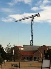
Engineering Connection
Complex engineered structures can be described as tall buildings, bridges, tunnels and highways. The use of mathematics in engineering is important because each of these structures has a different design depending on its purpose and where it is built. While the math associated with the design of complex structures is difficult (precisely figuring out the beams, columns and floors of a structure, for example), another application for math exists, one that is not as complex. The bidding phase of a project, for instance, also involves the use of math for estimations and unit conversions—a simpler but also important type of math than what is used to design vital structure components.
Learning Objectives
After this activity, students should be able to:
- Estimate the cost and weight of a design project.
- By applying concepts of the engineering design process, explain how to build a bridge out of paper that can hold more than its own weight.
- Explain the different type of failures that occur in buildings.
- Describe how the accuracy equation can be used.
- (If Microsoft Excel® is used): Use a software spreadsheet application to tabulate results and/or use an ultrasonic sensor to measure distance.
Educational Standards
Each TeachEngineering lesson or activity is correlated to one or more K-12 science,
technology, engineering or math (STEM) educational standards.
All 100,000+ K-12 STEM standards covered in TeachEngineering are collected, maintained and packaged by the Achievement Standards Network (ASN),
a project of D2L (www.achievementstandards.org).
In the ASN, standards are hierarchically structured: first by source; e.g., by state; within source by type; e.g., science or mathematics;
within type by subtype, then by grade, etc.
Each TeachEngineering lesson or activity is correlated to one or more K-12 science, technology, engineering or math (STEM) educational standards.
All 100,000+ K-12 STEM standards covered in TeachEngineering are collected, maintained and packaged by the Achievement Standards Network (ASN), a project of D2L (www.achievementstandards.org).
In the ASN, standards are hierarchically structured: first by source; e.g., by state; within source by type; e.g., science or mathematics; within type by subtype, then by grade, etc.
NGSS: Next Generation Science Standards - Science
| NGSS Performance Expectation | ||
|---|---|---|
|
HS-ETS1-3. Evaluate a solution to a complex real-world problem based on prioritized criteria and trade-offs that account for a range of constraints, including cost, safety, reliability, and aesthetics, as well as possible social, cultural, and environmental impacts. (Grades 9 - 12) Do you agree with this alignment? |
||
| Click to view other curriculum aligned to this Performance Expectation | ||
| This activity focuses on the following Three Dimensional Learning aspects of NGSS: | ||
| Science & Engineering Practices | Disciplinary Core Ideas | Crosscutting Concepts |
| Evaluate a solution to a complex real-world problem, based on scientific knowledge, student-generated sources of evidence, prioritized criteria, and tradeoff considerations. Alignment agreement: | When evaluating solutions it is important to take into account a range of constraints including cost, safety, reliability and aesthetics and to consider social, cultural and environmental impacts. Alignment agreement: | New technologies can have deep impacts on society and the environment, including some that were not anticipated. Analysis of costs and benefits is a critical aspect of decisions about technology. Alignment agreement: |
Common Core State Standards - Math
-
Reason abstractly and quantitatively.
(Grades
K -
12)
More Details
Do you agree with this alignment?
-
Model with mathematics.
(Grades
K -
12)
More Details
Do you agree with this alignment?
-
Reason quantitatively and use units to solve problems.
(Grades
9 -
12)
More Details
Do you agree with this alignment?
-
Solve equations and inequalities in one variable
(Grades
9 -
12)
More Details
Do you agree with this alignment?
-
Solve linear equations and inequalities in one variable, including equations with coefficients represented by letters.
(Grades
9 -
12)
More Details
Do you agree with this alignment?
International Technology and Engineering Educators Association - Technology
-
Students will develop an understanding of the attributes of design.
(Grades
K -
12)
More Details
Do you agree with this alignment?
-
Students will develop an understanding of engineering design.
(Grades
K -
12)
More Details
Do you agree with this alignment?
-
Students will develop abilities to apply the design process.
(Grades
K -
12)
More Details
Do you agree with this alignment?
-
A prototype is a working model used to test a design concept by making actual observations and necessary adjustments.
(Grades
9 -
12)
More Details
Do you agree with this alignment?
-
Illustrate principles, elements, and factors of design.
(Grades
9 -
12)
More Details
Do you agree with this alignment?
-
Document trade-offs in the technology and engineering design process to produce the optimal design.
(Grades
9 -
12)
More Details
Do you agree with this alignment?
State Standards
New York - Math
-
Reason abstractly and quantitatively.
(Grades
Pre-K -
12)
More Details
Do you agree with this alignment?
-
Model with mathematics.
(Grades
Pre-K -
12)
More Details
Do you agree with this alignment?
-
Reason quantitatively and use units to solve problems.
(Grades
9 -
12)
More Details
Do you agree with this alignment?
-
Solve quadratic equations in one variable.
(Grades
9 -
12)
More Details
Do you agree with this alignment?
-
Solve linear equations and inequalities in one variable, including equations with coefficients represented by letters.
(Grades
9 -
12)
More Details
Do you agree with this alignment?
New York - Science
-
Evaluate a solution to a complex real-world problem based on prioritized criteria and trade-offs that account for a range of constraints, including cost, safety, reliability, and aesthetics, as well as possible social, cultural, and environmental impacts.
(Grades
9 -
12)
More Details
Do you agree with this alignment?
Materials List
Each group needs:
- glue stick
- roll of transparent tape
- ruler
For the class to share (to be "purchased" by each group):
- printer or copier paper (can be recycled)
- construction/craft paper (stiffer than printer paper)
- index cards
For teachers use only:
- 12-inch length of fishing line or other nylon/strong string
- 1-2 foam/paper cup (only one is needed, but have a back-up)
- variety of incremental weights (between 5 g - 20 g)
- digital scale (with a resolution of 1g)
- (optional) LEGO MINDSTORMS EV3 ultrasonic sensor. Note: This activity can also be conducted with the older LEGO MINDSTORMS NXT set.
- (optional) access to computer with Microsoft Excel®
Worksheets and Attachments
Visit [www.teachengineering.org/activities/view/nyu_boom_activity1] to print or download.Pre-Req Knowledge
An understanding of equations and equation format.
Introduction/Motivation
Today we are going to learn what it takes to be a civil engineer. Civil engineering is a profession in which you create structures and infrastructure such as buildings, traffic systems, bridges, roads, transportation models, rivers and water networks (among other things). Civil engineers regularly use the engineering design process in their projects to help them find optimal solutions. The primary steps that compose the engineering design process are: ask to identify the problem, research the problem, imagine possible solutions, plan by selecting a design, create, test, and iterate/improve. They are explained as:
- Ask: Identify the Needs and Constraints: What is the problem? What do we want to accomplish? What are the project requirements? What are the limitations? Who is the customer? What is our goal?
- Research the Problem: Gather information and conduct research, talking to people from many different backgrounds.
- Imagine possible solutions: Imagine and brainstorm ideas. Be creative; build upon the wild and crazy ideas of others. Investigate existing technologies and methods to use. Explore, compare and analyze many possible solutions.
- Plan by selecting a design: Based on the needs identified, select the most promising idea. Draw a diagram of your idea. How will it work? What environmental and cultural considerations will you evaluate? What materials and tools are needed? What analyses must you do? How will you test it to make sure it works?
- Create: Assign team tasks. Build a prototype and test it against your design objectives. Push yourself for creativity, imagination and excellence in design.
- Test and Evaluate Prototype: Does it work? Analyze and talk about what works, what doesn't and what could be improved.
- Improve: Discuss how you could improve your product. Make revisions. Draw new designs. Iterate your design to make your product the best it can be.
By following the steps of the engineering design process, we will design and build a boom. What is a boom? Well, a boom is something that can hold more than its own weight and performs a job. For example, a bridge is a boom. The deck of a bridge has one job: to provide a flat area (deck) for trucks and people to cross over something below (such as, water, wetlands, debris, canyon, ditch, highway, empty space, etc.). A deck bridge usually consists of trusses, placed either on top of the bridge or below it. A truss is a combination of beams (posts or sticks) that form triangles. Whether you realize it or not, you have seen many of these creations: the floors and ceilings of structures such as office buildings, homes, shopping centers, subways, and many roofs—all are made of trusses. Trusses are very useful for engineers because they are lightweight, yet strong structures. 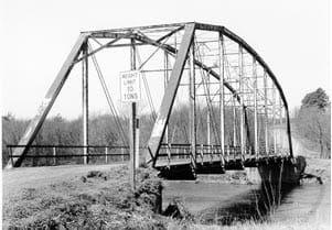
[Show students Figures 1 and 2, or other pictures of trusses, I-beams and deck bridges. Point out the difference in bridges with trusses on top vs. beneath bridge decks.]
A simple beam can also be a boom. A beam is just a stick (or post or pole) that can hold weight. Think of a diving board or a fallen tree that spans a creek. Civil engineers make sure that they use the right size beams that can hold the anticipated amount of weight (load) in order to avoid collapse (failure). This might make you ask, "Why don't we just put large beams everywhere?" The answer is simple. Money limitations, or the project budget, is something that civil engineers must pay attention to on every project. A civil engineering company signs a contract, which is an agreement (or promise), that it will complete the project by a certain date and at a certain cost. Both date and cost are called constraints—a concept that is the foundation of the fundamentals of engineering, "designing within constraints."
Many companies go through a bidding phase to find an engineering firm to design and complete a project. A bidding phase is when many companies bid on how much money it will take them to finish the project by a required date. Usually the company with lowest bid wins the contract, unless the firm is not qualified for the job. 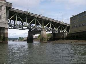
Today we will complete two engineering tasks: 1) design a project (bridge) and 2) estimate its cost (bid). We will learn on how to build a good bridge using only paper by going through an engineering process called modeling or prototyping. Modeling is seeing the desired effects on a much smaller scale in order to save money. We also learn how to use accuracy equations and estimations in order to be on budget.
This activity also involves a competition. Within your groups, you each will be assigned one of three roles, just like a real job at a company. The team with the best estimation and strongest bridge wins.
Procedure
Background
Failure
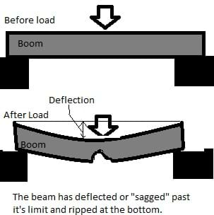
The concepts of shear failure and bending failure are very important in bridge design. When dealing with building structures, a beam can fail in two main ways. These failures are demonstrated in Figures 3 and 4. Beams are important in preventing failure; your boom can be made of as many beams as your design specifies.
Bending Failure
As illustrated in Figure 3, a beam can physically break when the load applied is such that the beam sags past it's limit. For example, if you take a ruler and try to bend it, it will bend a bit, but at some point it will break. However, bending also provides another mode of failure, which relates to the amount of sag that is allowed. For example, if the bending ruler doesn't break, it can create quite a steep curve, but would you feel safe walking on that ruler? This is why in civil engineering, limits have been established to prevent very large sags or also known as deflections. This deflection is usually related and proportional to the length of the beam. This is what we will measure in this competition. Every team will be limited to a certain amount of deflection (see the rules) .
Shear Failure
Shear failure can be imagined as a "cutting" failure. When a load is so large, it can physically crush or cut the beam in half. This is the worst kind of failure, because it does not give any warning before the break occurs, as opposed to the bending failure in which you can feel the beam curvature. This is very important to consider because your booms will be made of paper. If you do not put stiff materials under where the load will be applied, you will crush the beam at that point. Some ways you can prevent crushing is by filling the inside of the beam with strong material, such as index cards.
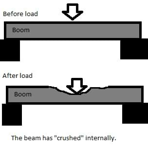
This activity consists of two parts. Part I is the planning phase, during which time students brainstorm their bridge/boom designs and draw their designs. In the planning phase, teams prepare everything they need to build their projects. Part II is the building phase.
In Part I, introduce team tasks and the competition rules. This allows students to plan accordingly and prepare their best estimations.
Assign the following team tasks. Have groups discuss among themselves who will complete each task.
- Cost Estimator – estimates the final project cost and figures out how to reduce the project cost.
- Materials Estimator – estimates the final project weight and figures out how to reduce the boom weight, while not compromising strength.
- Structural Designer – listens to team suggestions and sketches a drawing of the selected design.
Competition Rules (aka engineering challenge requirements)
- Each team may use as much of the materials as it wants, but some materials have a cost. Other materials are without cost (free), but may add unnecessary weight.
- Each bridge/boom must span (go across) an 11-inch space. Tip: This distance can be increased, but doing so may make bridges fail sooner, with less weight.
- Each bridge will be loaded at increments of 5 g - 20 g, until it fails.
- Each bridge is considered to fail once it has "sagged" or deflected by the ratio shown below. A ratio is used in civil engineering to measure acceptable deflections in the real world. This ratio is modified to allow greater sag to allow more competitiveness among teams.

Equation for measuring acceptable deflection.
This means that once your bridge has sagged by .5 inch., it is considered to fail at the weight that it is currently holding. At the initial point of sagging, wait about 5 seconds before considering a bridge as failed, due to wave and spring motion (bridge bouncing up and down from the weight being loaded into the cup).
NOTE: If a LEGO EV3 sensor is used to measure this distance, do it in centimeters with a value of 2. The sensor already has this value built into the program.
- ONLY the following materials, sold at the stated costs, may be used to construct bridges:
- construction paper @ $0.145/sheet (if no stiffer than printer paper, reduce this cost to the same as printer paper)
- printer or copy paper (11 x 8 in) @ $0.065/sheet
- index cards @ $0.035/card
- tape (free)
- glue stick (free)
- scissors (free)
- The group that wins the competition is the team with the highest final ratio (FR). The FR consists of the following four ratios:
- weight ratio (WR) – ratio between final weight and boom self-weight
- cost ratio (CR) – ratio of final cost and a constant
- cost estimation ratio (CER) – determines the accuracy of cost estimation
- weight estimation ratio (WER) – determines the accuracy of self-weight estimation
![FR=(WR+CR)(WER)(CER), where WR = 4 x weight held (g) / self weight (g), CR = 2 / cost of boom ($), CER = 1 – [|cost of boom ($) – estimated cost of boom ($) / cost of boom ($)] and WER = 1 – [|self weight (g)– estimated weight of boom (g) / self weight (g)] FR=(WR+CR)(WER)(CER), where WR = 4 x weight held (g) / self weight (g), CR = 2 / cost of boom ($), CER = 1 – [|cost of boom ($) – estimated cost of boom ($) / cost of boom ($)] and WER = 1 – [|self weight (g)– estimated weight of boom (g) / self weight (g)]](/content/nyu_/activities/nyu_boom/nyu_boom_activity1_equation2.jpg)
Equation 2. How to calculate the final ratio (FR).
NOTE: Both CER and WER should be 0<CER&WER<1, thus reducing CR by the error percentage. Both CER and WER are accuracy equations that use absolute value.
- Make sure that students understand that these equations are essentially "accuracy equations." To further explain the concepts, draw a target on the classroom board. Color in red dots to represent dart "hits," as shown in Figure 5. Now apply Equation 2 to calculate how accurate you are to the desired score. In the example below, the desired value would be 4 x 10 = 40 points. The actual value is 2 x 5 + 2 x 7 = 24. Now apply the accuracy equation.
%Accurate=1 – [ |Desired Score – Actual Score| / Desired Score ]
%Accurate=1 – [ |40 – 24| / 40 ]=0.6
So we are 0.6 accurate with our desired score. Explain that this could be turned into a percentage by multiplying it by 100.
NOTE: An accuracy equation can be applied to anything, as it simply states how close you are to your desired value, either in decimals or in percentage. It is used to find the weight estimation ratio and cost estimation ratio, where for weight, the desired value is the final bridge weight (the one the scale will read), and the actual number is the students' guess (before it's weighed). Same for cost ratio, whereby desired is what you think it will cost vs. how much it actually ended up costing. 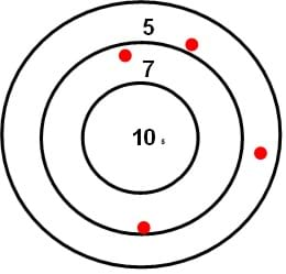
- Groups must provide their estimated costs and estimated weights to the teacher prior to the start of Part II and are not permitted to change them. Teams may only alter these values during Phase I (planning).
- The boom may not be taped to the table (or to supporting structures).
Before the Activity
- (optional) Open the attached Boom Construction Calculation Form (Excel file) to tabulate each group's results at the end of each activity. A sample version of a completed Excel sheet is also attached. Alternatively, if not using Excel, draw a table on the board to record and tabulate results. Not using Excel for calculations may prolong the activity time.
- (optional) Open and upload the attached LEGO MINDSTORMS EV3 program, Deflection Measure (ev3 file). Read the attached MINDSTORMS EV3 Sensor Assembly Instructions to set up the sensor to measure bridge deflection. Alternatively, students may use a ruler, which works just as well and speeds up the activity.
- (optional) Search the Internet to find some images of trusses, I-beams and deck bridges to show the class. See Figures 1 and 2 as examples.
- Write the steps of the engineering design process on the classroom board: identify the problem, brainstorm solutions, select a design, plan, build and test, iterate/improve.
With the Students
Part I: Planning Phase (1.5 hrs)
- Divide the class into teams of three students each. Avoid creating four-person teams unless you have one or two students beyond what is needed to make three-person teams.
- Have each group agree on a unique name for its engineering firm. To stay on schedule, allow no more than five minutes for this task. Enter the team names into the Excel file.
- While students are discussing/deciding upon their team names, write the material prices on the classroom board.
- Assign the group member roles of: cost estimator, materials estimator and structural designer, as described earlier.
- Next, review with the entire class the activity competition rules (see above; also listed on the Boom Construction Contract Form). In the real-world, these would be considered project requirements or constraints.
- Remind students of the concepts of bending and shear failure, and show them pictures of trusses, I-beams and deck bridges.
- Have groups brainstorm bridge/boom designs and estimate their total building costs and weights, while performing their assigned roles. Have students use the attached Boom Construction Contract Form for purchasing materials.
- Using a digital scale, weigh each piece of building material that groups use and convert this into either weight per area or weight per linear unit.
For example: Place an 11 x 8.5-in piece of printer paper on the scale. It should weigh ~5 g. Divide 5 g by (11 x 8) to find weight per square inch, which equals the value that students should use to estimate the weight of their booms. Permit students to use the standard weight of 5 g for each sheet of paper used.
Tip: Have students calculate the total number of sheets they estimate they using, and then after they build their bridges, they can subtract any unused paper using the weight per sq in rule.
Tip: To measure tape and glue, run a known length of glue/tape down a known weight sheet of 5 g paper and then measure the difference in weight. Represent this weight with units of g per inch.
- Record the estimation and weight values for each team; from this point forward, these may not be changed.
Part II: Building Phase (2 hrs)
- Have one student from each team pick up the materials "purchased" on the Boom Construction Contract Form.

Figure 6. Example "weight" cup with threaded string. - Have groups begin building their bridges, while still being able to buy more materials as they progress Note: Remind students that estimation values may not be changed.
- While teams are building, set up a testing station by placing two chairs or desks 11 inches apart. If a LEGO EV3 sensor is used, position it on the floor under the testing station.
- Prepare the foam/paper cup with a string with paper clips on both sides to be used to add the incremental weights. The string can either have one paper clip on each end to be used as hooks to attach to the cup's holes (see Figure 6). Or, it can be threaded through the holes in the cup and then two paper clips on each end can hook to each other as the string is placed on each side of the bridge.
- Once a team is done building and its boom is ready for testing, measure and record its weight in the Excel file.
- Place the boom over the 11-inch gap with the string placed through/on the middle of the boom. Note: Placing the string in the middle is very important for fairness amongst teams.
- If using a LEGO EV3 sensor, set it to record the distance between the cup and the sensor. If using a ruler to measure the sag/deflection, position it perpendicular to the floor.
- Gently load weight increments of 5 g - 20 g into the cup until the bridge sags 2 cm if using an EV3 or 0.5 in if using a ruler (see Figure 7).
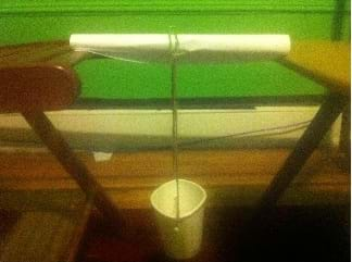
Figure 7. Placement of the hanging cup from a test boom.
- Once a boom fails, weigh the cup and record this value in the Excel file as "weight held."
- Once all values are entered, calculate the team ratios.
- Once the calculations are made, announce a winner.
- Discuss as a class what made the winning boom stronger than the other booms (see Figure 8). Have students brainstorm ways they could modify their booms to make them stronger.

Figure 8. Due to its simplistic and light design, this student-constructed boom scored the highest.
Vocabulary/Definitions
bending failure: Failure of a beam based on bending beyond its load limit.
bidding: Putting in your estimation for a contract in order to try to win it.
contract: An agreement.
deflection: How much something has "sagged" or moved.
load: Anticipated weight applied to a bridge structure. Includes self-weight.
self-weight: The weight of the object itself.
shear failure: Failure of a beam based on crushing or cutting.
structural: (structure) Anything related to the building. In engineering it is usually anything related to the "load" carrying parts of a building.
Assessment
Pre-Activity Assessment
Construction Pre-Quiz: Ask the following questions to gauge students' knowledge of bridge design and related concepts. If you wish to grade this quiz, ask students to write their answers, with corresponding numbers, on a sheet of paper; collect responses and review their answers to gauge their baseline knowledge (see the attached Answer Key for example answers).
- Why is it important to estimate the cost and how much material will be needed for a building project?
- How are cost and material estimations used by engineers?
- What is an accuracy equation?
- What is deflection?
- Must a bridge collapse in order for civil engineers to consider it "failed"?
- What is shear failure?
Activity Embedded Assessment
Accuracy Equation: Make sure students understand the equation and then apply it to the activity, where the desired score is equivalent to the self-weight of the bridge after it has been tested, and the actual score is the estimation. Note: The accuracy equation may seem a bit counter-intuitive to students at first; explain that the denominator is the number they are trying to get.
Post-Activity Assessment
Construction Post-Quiz: Again, ask students the pre-assessment quiz questions to gauge their knowledge of bridge design and related concepts after the completion of the activity. If you wish to grade this quiz, ask students to write their answers, with corresponding numbers, on a sheet of paper; collect responses and review their answers to gauge their level of comprehension.
Investigating Questions
- What makes one bridge stronger than another?
- What type of material works better than other types? Why?
- When building a bridge, is it better to sacrifice cost or weight? Why? Why not?
- Does the number of trusses used determine the carrying capacity (load) of a bridge?
Troubleshooting Tips
- Over time, some EV3 ultrasonic sensors may not accurately measure the sag; unfortunately, no fix exists for the calibrating measurements. It is recommended that you test any sensor and program prior to activity to verify its reliability.
- Since some bridges fail quickly, begin with a small amount of weight, slowly incrementing as the bridge continues to hold up
- The weight cup may become lopsided during loading; prevent the cup from tipping over by spreading the weight inside the cup.
- Make sure students understand that bridges must be built longer than 11inches so that they span the 11-inch gap.
- The accuracy equation is easier to first explain in terms of how it can be used to figure out how "accurate" a dart shot is, then diving right into the desired cost/desired weight accuracy as pertains to the activity.
Activity Extensions
If time allows, have students redesign their bridges to make them stronger. Repeat the testing steps.
Subscribe
Get the inside scoop on all things Teach Engineering such as new site features, curriculum updates, video releases, and more by signing up for our newsletter!More Curriculum Like This

Learn the basics of the analysis of forces engineers perform at the truss joints to calculate the strength of a truss bridge known as the “method of joints.” Find the tensions and compressions to solve systems of linear equations where the size depends on the number of elements and nodes in the trus...

Students learn about the major factors that comprise the design and construction cost of a modern bridge. Students learn about the components that go into estimating the total cost, including expenses for site investigation, design, materials, equipment, labor and construction oversight, as well as ...

Students are presented with a brief history of bridges as they learn about the three main bridge types: beam, arch and suspension. They are introduced to two natural forces — tension and compression — common to all bridges and structures.

Students take a close look at truss structures, the geometric shapes that compose them, and the many variations seen in bridge designs in use every day. Through a guided worksheet, students draw assorted 2D and 3D polygon shapes and think through their forms and interior angles (mental “testing”) be...
Copyright
© 2013 by Regents of the University of Colorado; original © 2012 Polytechnic Institute of New York UniversityContributors
Stanislav Roslyakov; Janet YowellSupporting Program
AMPS GK-12 Program, Polytechnic Institute of New York UniversityAcknowledgements
This activity was developed by the Applying Mechatronics to Promote Science (AMPS) Program funded by National Science Foundation GK-12 grant no. 0741714. However, these contents do not necessarily represent the policies of the NSF, and you should not assume endorsement by the federal government.
Additional support was provided from the Central Brooklyn STEM Initiative (CBSI), funded by six philanthropic organizations.
Last modified: August 27, 2020





User Comments & Tips