Quick Look
Summary
Students explore the fundamentals of digital logic by building truth tables and designing their own logic circuits. Using a series of scaffolded worksheets, students gain hands-on experience with core logic gates such as AND, OR, NOT, NAND, NOR, XOR, and XNOR. They apply this knowledge by analyzing multi-input circuits and eventually designing their own four-input logic system. On the final day, students use the free online circuit simulator Wokwi to test and verify their custom logic gate designs. Through this activity, students gain foundational experience in binary reasoning, digital electronics, and circuit logic that underpins real-world computing systems.Engineering Connection
Engineers use logic gates to design everything from smartphone processors to self-driving-car sensors. These gates form the foundation of digital systems, helping engineers create circuits that make decisions based on input signals. Electrical and computer engineers simulate logic designs digitally before building them, just like students do in this activity using Wokwi. When designing a circuit, engineers consider the number of inputs, how they combine, what conditions trigger an output, and how reliable the system is. Logic systems must be efficient, scalable, and precise, especially in safety-critical technologies such as medical devices, robotics, or aerospace systems.
Learning Objectives
After this activity, students should be able to:
- Identify and interpret the function of basic logic gates and their corresponding truth tables.
- Design and simulate a multi-input logic circuit using digital tools to meet a specific logical condition.
- Apply systems thinking and symbolic reasoning to analyze input-output relationships in digital circuits.
Educational Standards
Each TeachEngineering lesson or activity is correlated to one or more K-12 science,
technology, engineering or math (STEM) educational standards.
All 100,000+ K-12 STEM standards covered in TeachEngineering are collected, maintained and packaged by the Achievement Standards Network (ASN),
a project of D2L (www.achievementstandards.org).
In the ASN, standards are hierarchically structured: first by source; e.g., by state; within source by type; e.g., science or mathematics;
within type by subtype, then by grade, etc.
Each TeachEngineering lesson or activity is correlated to one or more K-12 science, technology, engineering or math (STEM) educational standards.
All 100,000+ K-12 STEM standards covered in TeachEngineering are collected, maintained and packaged by the Achievement Standards Network (ASN), a project of D2L (www.achievementstandards.org).
In the ASN, standards are hierarchically structured: first by source; e.g., by state; within source by type; e.g., science or mathematics; within type by subtype, then by grade, etc.
NGSS: Next Generation Science Standards - Science
| NGSS Performance Expectation | ||
|---|---|---|
|
HS-ETS1-2. Design a solution to a complex real-world problem by breaking it down into smaller, more manageable problems that can be solved through engineering. (Grades 9 - 12) Do you agree with this alignment? |
||
| Click to view other curriculum aligned to this Performance Expectation | ||
| This activity focuses on the following Three Dimensional Learning aspects of NGSS: | ||
| Science & Engineering Practices | Disciplinary Core Ideas | Crosscutting Concepts |
| Design a solution to a complex real-world problem, based on scientific knowledge, student-generated sources of evidence, prioritized criteria, and tradeoff considerations. Alignment agreement: | Criteria may need to be broken down into simpler ones that can be approached systematically, and decisions about the priority of certain criteria over others (trade-offs) may be needed. Alignment agreement: | |
| NGSS Performance Expectation | ||
|---|---|---|
|
HS-ETS1-4. Use a computer simulation to model the impact of proposed solutions to a complex real-world problem with numerous criteria and constraints on interactions within and between systems relevant to the problem. (Grades 9 - 12) Do you agree with this alignment? |
||
| Click to view other curriculum aligned to this Performance Expectation | ||
| This activity focuses on the following Three Dimensional Learning aspects of NGSS: | ||
| Science & Engineering Practices | Disciplinary Core Ideas | Crosscutting Concepts |
| Use mathematical models and/or computer simulations to predict the effects of a design solution on systems and/or the interactions between systems. Alignment agreement: | Both physical models and computers can be used in various ways to aid in the engineering design process. Computers are useful for a variety of purposes, such as running simulations to test different ways of solving a problem or to see which one is most efficient or economical; and in making a persuasive presentation to a client about how a given design will meet his or her needs. Alignment agreement: | Models (e.g., physical, mathematical, computer models) can be used to simulate systems and interactions—including energy, matter, and information flows—within and between systems at different scales. Alignment agreement: |
| NGSS Performance Expectation | ||
|---|---|---|
|
HS-PS4-2. Evaluate questions about the advantages of using a digital transmission and storage of information. (Grades 9 - 12) Do you agree with this alignment? |
||
| Click to view other curriculum aligned to this Performance Expectation | ||
| This activity focuses on the following Three Dimensional Learning aspects of NGSS: | ||
| Science & Engineering Practices | Disciplinary Core Ideas | Crosscutting Concepts |
| Evaluate questions that challenge the premise(s) of an argument, the interpretation of a data set, or the suitability of a design. Alignment agreement: | Information can be digitized (e.g., a picture stored as the values of an array of pixels); in this form, it can be stored reliably in computer memory and sent over long distances as a series of wave pulses. Alignment agreement: | Systems can be designed for greater or lesser stability. Alignment agreement: Modern civilization depends on major technological systems.Alignment agreement: Engineers continuously modify these technological systems by applying scientific knowledge and engineering design practices to increase benefits while decreasing costs and risks.Alignment agreement: |
Common Core State Standards - Math
-
Reason abstractly and quantitatively.
(Grades
K -
12)
More Details
Do you agree with this alignment?
Materials List
Each student needs:
- 1 printed copy of the Logic Gates and Truth Tables Reference Sheet
- 1 printed copy of the Logic Gates I Worksheet
- 1 printed copy of the Logic Gates II Worksheet
- 1 printed copy of the Logic Gates III Worksheet
Each group needs:
- 1 laptop or Chromebook with internet access
- access to the Wokwi simulator (https://wokwi.com)
- pencil and eraser
For the entire class to share:
- access to a classroom projector or screen (for instructor demonstration of Wokwi simulation)
- whiteboard or poster paper for logic diagram modeling
- colored markers or pens for truth table visualization
Digital and Multimedia Resources:
- Wokwi Logic Gate Simulator; https://wokwi.com
- Used by students to build and test custom logic circuits in the final design challenge
- Note: This website was not blocked by our network services, but the subdomain of wokwi.github.io
- Wokwi Four-Input Logic Gate Simulator Template
- Custom-made template with instructions for students to use for the final product of the activity
- https://wokwi.com/projects/430117426135868417
- YouTube Video “Size Matters: Human Hair vs Apple iPhone 5 nm Chip”
- https://www.youtube.com/shorts/GCcKW8KB_lo (0:57)
- Hook video to show the mind-boggling size of the physical structures of logic gates in advanced chips.
- Optional: Canvas Creative Commons Pages
- Linked below are my Canvas modules and pages related to this activity. They include information, tutorials, and additional background information that can be used to augment or scaffold your implementation of this activity!
- https://okcps.instructure.com/courses/221876
Worksheets and Attachments
Visit [www.teachengineering.org/activities/view/oks-2995-unlocking-secrets-semiconductors-logic-gates-activity] to print or download.Pre-Req Knowledge
No prerequisite knowledge of Boolean logic is required, as the activity is designed to introduce students to logic gates, truth tables, and digital reasoning from the ground up.
Students should have:
- A basic understanding of how electricity flows through circuits (on/off, open/closed concepts).
- The ability to interpret simple tables and identify input/output relationships.
- Familiarity with terms such as “input,” “output,” and “system” in a general science or math context.
- Basic keyboard and web navigation skills (to be able to use a simulation platform such as Wokwi).
Introduction/Motivation
Logic is all around us. It is the process of making decisions based on clear rules: If this happens, then do that. We use logic every day, whether we are deciding what to eat, choosing which route to take to school, or solving problems in games and puzzles. When you follow a recipe, you are using logic—if the water boils, then add the pasta. If you miss your alarm, then you run to catch the bus.
Can you think of a moment today where you used an “if this, then that” kind of decision? What happened? (Possible answers: If I miss breakfast, I grab a granola bar. If my phone battery is low, I plug it in.)
Logic is a way to reduce any kind of complicated question or process into the simplest terms—yes or no, true or false. This same kind of thinking is used in systems built by engineers and programmers. From traffic lights to phone notifications, logic determines what actions a system takes based on inputs. It is the backbone of automation, control systems, and computing.
Let’s take two minutes to write a one-sentence definition of “logic” in your own words and give a real-life example of how you have used it. (Give students two minutes to complete the prompt. Have a few students share their answers. Possible answers: “Logic is how you make decisions based on rules.” “If I don’t sleep, I feel tired.”)
Now, where do you think logic exists in machines? What systems have you seen or used that seem to make decisions without a person involved? (Write student answers on the board. Prompt them to think beyond computers, e.g., vending machines, traffic lights, elevators, motion-sensor lights, or smart speakers.)
In electronics, logic becomes a physical system. Engineers use what are called logic gates, small electronic circuits that follow basic logical rules. A gate might turn something on only if two inputs are both active, or turn something off if one input is active. These gates are built using semiconductors, which are special materials such as silicon that can act as both conductors and insulators. Inside a gate, transistors made of semiconductors function like tiny switches, controlling the flow of electricity based on input signals. This is how “if this, then that” logic becomes the foundation of real machines. Logic gates are the building blocks of everything from calculators to gaming consoles to self-driving cars.
Why might it be important for systems like these to always follow exact rules? (Possible answers: Safety, reliability, no guessing, needs to work the same way every time.)
Today’s activity gives you the chance to explore how logic works in electronics. You will start by learning how each gate behaves and how inputs affect outputs. Then, you will combine gates into more complex systems. Finally, you will use a tool engineers use, called a digital simulator, to design and test a system of your own.
By the end of this activity, you will not just understand logic; you’ll be using it to build something that works!
Procedure
Background
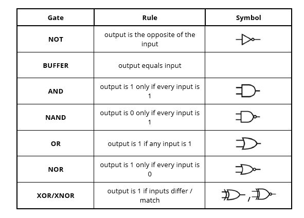
Boolean algebra is a branch of mathematics that reduces any statement to two possible values: true (1) or false (0). Electronic engineers embed these true/false decisions in logic gates. Each gate is a tiny circuit that accepts one or more binary inputs and produces a binary output according to a rule. Image 1 shows the seven gates that are used in this activity.
Logic gates are the basic building blocks of digital circuits, and they rely on semiconductors to function. Inside each gate, semiconductor devices such as transistors act as electronic switches that control the flow of current based on input signals. By arranging these transistors in specific ways, semiconductors allow logic gates to perform fundamental operations such as AND, OR, and NOT, which combine to form complex circuits found in computers, smartphones, and nearly all modern electronics.
Before fabricating silicon, engineers prototype gate networks in software. One free browser-based tool is Wokwi (https://wokwi.com). Students will use Wokwi to drag‐and-drop gates, wire inputs, and view live truth-table outputs.
Before the Activity
- Gather laptops/Chromebooks (1 per group) with internet access.
- Print one copy per student of:
- Logic Gates and Truth Tables Reference Sheet
- Logic Gates I Worksheet
- Logic Gates II Worksheet
- Logic Gates III (Four-Input Challenge) Worksheet
- Create or bookmark a class link to Wokwi Logic Gate Simulator:
- (https://wokwi.com/projects/430117426135868417)
- Test the simulator and save a sample two-gate circuit to show students.
- Optional: Prepare a slide deck of gate symbols for quick review. Otherwise, draw the symbols as the class goes through them!
During the Activity
Day 1 – Introduction to Logic and Gate Behavior
- Begin with a short discussion of everyday “if…then” logic. Write two real-world examples on the board.
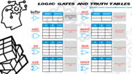
- Distribute the Logic Gates and Truth Tables Reference Sheet to the whole class.
- Go through each gate together. For each one:
- Model the gate’s symbol on the board or projector.
- Complete its truth table as a class.
- Provide a simple explanation of how it transforms input into output.
- Introduce Logic Gates I Worksheet as a puzzle activity where students must use deductive reasoning to complete each gate’s missing information.
- Each puzzle provides only one clue (either the gate’s name, truth table, or symbol).
- Students must complete the other two elements based on what they know.
- Example: A question may include a truth table, and students must identify the gate name and draw the correct symbol.
- Divide class into groups of up to four students each.
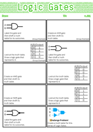
- Complete the first three worksheet problems as a class, modeling your thinking for each type of clue.
- Have students work in their groups to complete the remaining puzzle independently using their reference sheet.
- Allow students who finish early to attempt the challenge problem at the bottom, which introduces a three-input logic gate combination. (Hint: “You’ll need a truth table with eight rows, one for every combination of three binary inputs.”)
- End class with a preview of the challenge solution, emphasizing the process of building a three-input truth table from scratch.
Day 2 – Multi-Gate Practice and Structured Application
- Begin with a full-class debrief of the challenge problem from Logic Gates I. Model the three-input truth table and explain how to read from it.
- Distribute one Logic Gates II Worksheet to each student.
- Start by having every student fill out a standard two-input and three-input truth table provided at the top of the worksheet.
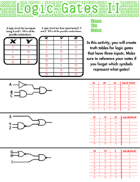
- Make sure all students complete it in the same order as you demonstrate. This becomes their reference for solving all remaining problems.
- Have students work in pairs to complete the rest of the Logic Gates II Worksheet using their completed truth tables as guides.
- Monitor students as they work on the Logic Gates II Worksheet, offering prompts such as:
- What happens when you add a third input?
- How do the combinations change from two inputs to three?
- Optional: For students who are unsure, go through the first problem of Logic Gates II together as an additional example. This gives confident students time to begin independently, while reinforcing understanding for others.
- Circulate and support as needed while students work on their worksheets.
- When students finish, provide a quick answer key for them to self-check. Emphasize that they are not expected to memorize gates, but rather to learn how to follow patterns and interpret behavior.
Day 3 – Four-Input Design and Digital Simulation in Wokwi
- Begin the day by distributing one Logic Gates III Worksheet to each student. This worksheet provides a full four-input truth table with all 16 binary input combinations already listed.
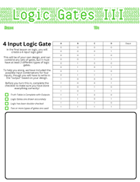
- Have students use the truth table to design a logic circuit of their own that will produce a unique output pattern with the requirements that the circuit must use at least two different types of gates. Students can use their Logic Gates and Truth Tables Reference Sheet.
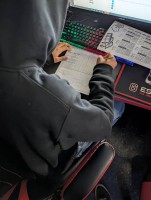
- Once their design is complete, have students predict the output for each of the 16 input rows and record it in the table on the worksheet. (Teacher prompt: “If A and B are both 1, what gate will activate?”)
- After completing the handwritten design and truth table, instruct students to open the Wokwi Logic Gate Simulator on their device: https://wokwi.com/projects/430117426135868417.

- Have students recreate their logic circuit using the drag-and-drop gate system in Wokwi.

- Guide students to test their inputs one by one and compare the digital output to their hand-drafted truth table.
- Remind students to answer two reflection questions in the Wokwi code section:
- What logic gates did you use, and why?
- How close was your prediction to the digital result? What would you change?
- Conclude with a whole-class discussion focusing on the following questions:
- What patterns did you notice?
- Where was your logic accurate? How accurate was it (how many outputs out of 16 were correct on the worksheet versus Wokwi)?
- How does designing with logic help us build smarter systems?
- Where have you noticed logic in the world this week?
Vocabulary/Definitions
AND gate: A gate that outputs true only if all inputs are true.
circuit: A complete path that allows electricity or signals to flow through components such as gates or wires.
digital system: A system that processes information using only two values: on/off or 1/0.
input: A signal or value that goes into a logic gate or system.
logic: A way of making decisions based on rules; used to determine whether something is true or false.
logic gate: A small circuit that follows a rule for turning inputs into an output (e.g., AND, OR, and NOT gates).
NOT gate: A gate that outputs the opposite of the input.
OR gate: A gate that outputs true if at least one input is true.
output: The result or response that comes out of a logic gate or system.
simulation: A digital model that lets engineers test how a system will work before building it in real life.
truth table: A chart that shows all possible input combinations and their resulting outputs for a logic circuit.
Assessment
Pre-Activity Assessment
Quick Write: What is logic? Ask students to write a one-sentence definition of “logic” in their own words and give a real-life example of how they have used it. (Possible answers: “Logic is how you make decisions based on rules.” “If I don’t sleep, I feel tired.”)
Group Discussion: Where do you think logic exists in machines? Lead a short, whole-class brainstorming session. Write student answers on the board. Prompt them to think beyond computers, e.g., what about vending machines, traffic lights, or elevators?
(Let students know there is no wrong answer; they are building intuition, not proving facts.)
Activity Embedded (Formative) Assessment
Logic Gates and Truth Tables Reference Sheet: Check for completion and accuracy as students work through each gate using the Logic Gates and Truth Tables Reference Sheet. Look for understanding of inputs and outputs.
Logic Gates I Puzzle Activity: Ensure students are correctly identifying missing gate names, symbols, or tables based on limited clues in the Logic Gates I Worksheet. Observe reasoning in groups.
Logic Gates II: Use a shared truth table at the beginning to establish a class-wide reference using the Logic Gates II Worksheet. Provide an answer key at the end for self-checking. Students should analyze differences and make corrections.
Challenge Check-In: During Logic Gates I and II, monitor how students attempt the three-input challenge problem. Offer prompts such as:
- “What happens when you add a third input?”
- “How do the combinations change from two inputs to three?”
Students do not need to solve it fully but should demonstrate persistence and pattern recognition.
Post-Activity (Summative) Assessment
Logic Gates III + Wokwi Design Challenge: Students compare their handwritten four-input truth table to the results of their Wokwi simulation on the Logic Gates III Worksheet. Ask them to reflect on:
- Which outputs matched their prediction?
- Where did they make a mistake in their logic, and why?
Written Reflection (in Wokwi "code" or classroom form):
- What gates did you choose, and why?
- How well did your logic design match the simulator?
- What would you do differently next time?
Class Discussion Wrap-Up: Facilitate a closing conversation where students share one new place they noticed logic in the world during the week. (Possible answers: “In a phone lock screen,” “in a game’s AI,” “in stoplights.”)
Troubleshooting Tips
- Cannot edit gates or wires in Wokwi: Check whether the simulation is still running. Students must click “Pause” to exit simulation mode before making changes to their design.
- Nothing happens when wires are connected: Remind students not to use the “clk” (clock) or “rst” (reset) pins on the input board. These are unused in your classroom template and will not trigger logic changes.
- Simulation does not save their work: Students must click “Save a Copy” in Wokwi before starting their design. Otherwise, any changes made in the template will not be saved when they share their simulation link.
- Outputs do not match the predicted truth table: Encourage students to compare each input row one at a time. A single misconnected input or incorrect gate can cause multiple rows to fail.
- Truth table looks wrong or incomplete: Remind students of input math: 3 inputs = 8 combinations, 4 inputs = 16. If they are missing rows, have them double-check their binary counting.
- General confusion on where to start when determining outputs or designing a logic gate series: Suggest students revisit the Logic Gates Reference Sheet and identify what kind of output pattern they want. Ask guiding questions such as “Do you want the output to be true only when all inputs are true?”
Activity Extensions
Optional Extension 1 – Infographic or Poster Design:
Ask students to turn their circuit and explanation into a visual summary. Include their logic diagram, truth table, and real-world application. This can be displayed or used for peer review.
Optional Extension 2 – Design a 1-Bit Binary Adder
Challenge students to design a circuit that performs binary addition using logic gates. A one-bit adder takes two inputs (A and B) and outputs a Sum and a Carry. Students can build their design on paper or simulate it in Wokwi using gates from the activity. Encourage them to reference a truth table and reflect on how logic gates are used to perform calculations in real computers.
Optional Extension 3 – NAND Game Challenge
Invite students to explore nandgame.com, a puzzle-based game where they build other logic gates using only NAND gates. This activity reinforces how NAND alone can be used to construct any digital circuit and deepens understanding of logic gate behavior.
Support Option 1 – Two-Input Truth Table Practice
Provide struggling students with a simplified truth table worksheet limited to two inputs and just three basic gates (AND, OR, NOT). Use color coding or pre-filled rows to reduce cognitive load.
Support Option 2 – Gate Matching Activity
Instead of solving full circuits, have students complete a card sort or worksheet where they match gate names, symbols, and descriptions. This reinforces recognition before application.
Support Option 3 – Use a Gate Simulator Demonstration Only
For younger students or those who need extra support, guide them through using the Wokwi simulator as a watch-and-follow demo. Allow them to observe changes without needing to build circuits from scratch.
Support Option 4 – Pre-Drawn Circuit Diagrams
Give students partially completed logic circuit diagrams and ask them to label the gates and complete the outputs. This reduces design complexity while reinforcing logic flow.
Subscribe
Get the inside scoop on all things Teach Engineering such as new site features, curriculum updates, video releases, and more by signing up for our newsletter!More Curriculum Like This

Students learn about the first attempts at machine learning and specifically about the perceptron model—a simplified model of a biological neuron.
References
NAND Game. nandgame.com, https://nandgame.com. Accessed 15 May 2025.
Wokwi. Wokwi Logic Simulator, https://wokwi.com. Accessed 15 May 2025.
Copyright
© 2025 by Regents of the University of Colorado; original © 2024 Oklahoma State UniversityContributors
Nicholas Casorio (primary author); Dr. John Hu, Oklahoma State University; Dr. Erin Dyke, Oklahoma State University; Dr. James Stine, Oklahoma State University; Hridi Prova Debnath, Graduate Researcher, Oklahoma State University; Zach Wilson, Graduate Researcher, Oklahoma State UniversitySupporting Program
RET Site: Chip Design Experiences for Teachers to Stimulate Semiconductor Education in Oklahoma, Oklahoma State UniversityAcknowledgements
This curriculum was developed under National Science Foundation RET grant number 2206941. Any opinions, findings, and conclusions or recommendations expressed in this material are those of the authors and do not necessarily reflect the views of the National Science Foundation. The lesson is part of a broader instructional unit on semiconductor education developed in response to the CHIPS and Science Act passed in 2022.
Last modified: October 1, 2025



User Comments & Tips