Quick Look
Grade Level: 8 (7-9)
Time Required: 30 minutes
Lesson Dependency: None
Subject Areas: Physical Science
Summary
This lesson introduces students to three of the six simple machines used by many engineers. These machines include the inclined plane, the wedge and the screw. In general, engineers use the inclined plane to lift heavy loads, the wedge to cut materials apart, and the screw to convert rotational motion into linear movement. Furthermore, the mechanical advantage describes how easily each machine can do work and is determined by its physical dimensions.Engineering Connection
Simple machines are extremely valuable to engineers since they are used to accomplish extraordinary amounts of work with ease. In particular, engineers can design a simple machine which provides a desired mechanical advantage so that work can be done efficiently and effectively. The inclined plane, wedge and screw are used in many engineering systems today, including stairs, can openers, and airplanes, among many others.
Learning Objectives
After this lesson, students should be able to:
- Explain how the inclined plane, wedge and screw make work easier.
- Identify how the inclined plane, wedge and screw are used in many familiar engineering systems today.
- Discuss the mechanical advantage of an inclined plane, wedge and screw.
Educational Standards
Each Teach Engineering lesson or activity is correlated to one or more K-12 science,
technology, engineering or math (STEM) educational standards.
All 100,000+ K-12 STEM standards covered in Teach Engineering are collected, maintained and packaged by the Achievement Standards Network (ASN),
a project of D2L (www.achievementstandards.org).
In the ASN, standards are hierarchically structured: first by source; e.g., by state; within source by type; e.g., science or mathematics;
within type by subtype, then by grade, etc.
Each Teach Engineering lesson or activity is correlated to one or more K-12 science, technology, engineering or math (STEM) educational standards.
All 100,000+ K-12 STEM standards covered in Teach Engineering are collected, maintained and packaged by the Achievement Standards Network (ASN), a project of D2L (www.achievementstandards.org).
In the ASN, standards are hierarchically structured: first by source; e.g., by state; within source by type; e.g., science or mathematics; within type by subtype, then by grade, etc.
NGSS: Next Generation Science Standards - Science
-
Science knowledge is based upon logical and conceptual connections between evidence and explanations.
(Grades 6 - 8)
More Details
Do you agree with this alignment?
-
All positions of objects and the directions of forces and motions must be described in an arbitrarily chosen reference frame and arbitrarily chosen units of size. In order to share information with other people, these choices must also be shared.
(Grades 6 - 8)
More Details
Do you agree with this alignment?
-
Use mathematical representations to describe and/or support scientific conclusions and design solutions.
(Grades 6 - 8)
More Details
Do you agree with this alignment?
Common Core State Standards - Math
-
Fluently add, subtract, multiply, and divide multi-digit decimals using the standard algorithm for each operation.
(Grade
6)
More Details
Do you agree with this alignment?
-
Solve real-world and mathematical problems involving the four operations with rational numbers.
(Grade
7)
More Details
Do you agree with this alignment?
-
Solve linear equations in one variable.
(Grade
8)
More Details
Do you agree with this alignment?
International Technology and Engineering Educators Association - Technology
-
Students will develop an understanding of the relationships among technologies and the connections between technology and other fields of study.
(Grades
K -
12)
More Details
Do you agree with this alignment?
-
Explain how knowledge gained from other content areas affects the development of technological products and systems.
(Grades
6 -
8)
More Details
Do you agree with this alignment?
State Standards
Colorado - Math
-
Fluently add, subtract, multiply, and divide multidigit decimals using standard algorithms for each operation.
(Grade
6)
More Details
Do you agree with this alignment?
-
Solve real-world and mathematical problems involving the four operations with rational numbers.
(Grade
7)
More Details
Do you agree with this alignment?
-
Solve linear equations and inequalities in one variable, including equations with coefficients represented by letters.
(Grades
9 -
12)
More Details
Do you agree with this alignment?
Colorado - Science
-
Predict and evaluate the movement of an object by examining the forces applied to it
(Grade
8)
More Details
Do you agree with this alignment?
-
Use mathematical expressions to describe the movement of an object
(Grade
8)
More Details
Do you agree with this alignment?
Pre-Req Knowledge
Students should have a familiarity with the six simple machines and their ability to make work easier, as described in Lesson 1 of this unit, "The Advantage of Machines."
Introduction/Motivation
Which of you students truly enjoy lifting or moving heavy objects? Such strenuous work consumes our energy, often leaving us feeling very tired and weary and, sometimes, injured if we lift or move objects improperly. This unfortunate result is precisely why engineers are continually thinking of ways we can do work easier — so that we can work smarter and not harder. One way engineers accomplish this is by designing machines that help make work easier and more efficient. More specifically, every machine today is comprised of one or more of the six known simple machines — the fundamental components of all mechanical machines. In this lesson, we will study three of these useful devices in detail: the inclined plane, the wedge and the screw. Although engineers use each of these three simple machines for different purposes, they all operate on the same mechanical principles.
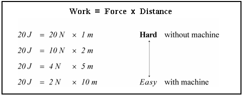
Before we go any farther, we need a brief review of the essential principles about simple machines (which will prove especially helpful when studying each individual machine). The most important fact is that simple machines never change the amount of work done, only the way in which work is done. Let's look at the definition of work, which is defined to be the product of force and distance and written mathematically as:
Since the amount of work to be done does not change for a particular chore, this value remains constant. However, both force and distance can in fact be altered. Simple machines often accomplish work differently by applying the input force, or effort, over a greater distance in order to make work easier to carry out. That is, in order to reduce the amount of force required to do the work, the distance must be proportionately increased. For example, let's say Emma the engineer needs to do 20 Joules worth of work. She can accomplish this in many different ways, one of which is to exert a force of 20 Newtons over a distance of 1 meter. However, an easier method may involve the application of a mere 2 Newton force over a distance of 10 meters. In either case, Emma does the same amount of work; however, it is much easier for her to accomplish this by applying less force over a further distance. Figure 2 illustrates how the same amount of work can be accomplished in many different ways, although some ways are easier — or more efficient — than others. This is the case when using a machine.
Inclined Plane
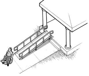
The inclined plane (see Figure 3) is perhaps the oldest and most rudimentary simple machine known to engineers. In fact, many of you are probably wondering how a slanted surface could possibly be classified as a "machine." Nevertheless, this device gives engineers the extraordinary ability to lift heavy objects to a higher position with ease.
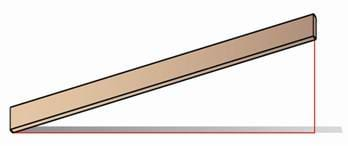
The key idea here is that less effort is needed if a load is transferred over a long ramp or inclined path, as opposed to lifting it directly over a vertical path. For example, you may have noticed how movers move very heavy objects, such as a piano, into the back of their moving truck. Obviously, they cannot easily lift such a heavy piece of furniture directly up and into the back of their truck. Instead, they use a long ramp — or inclined plane — to complete the job. This idea was used long ago by the ancient Egyptians: they used the inclined plane and human strength to erect monumental structures to amazing heights. Even today, engineers employ the inclined plane in many other applications in order to accomplish seemingly impossible tasks. Just a few of these examples include wheelchair ramps, escalators, stairs, highways and even hiking trails, which all rely on the inclined plane as a means of raising heavy objects more easily.
Wedge
In addition to lifting heavy objects, engineers are also interested in splitting or separating material with as little effort as possible. In this case engineers employ the use of a wedge so that tasks such as chopping firewood, cutting paper, and mowing our yards are made much easier. The wedge, as illustrated in Figure 4, is a simple machine often considered to be a slight variation of the inclined plane since it really consists of two inclined planes set back to back. As a result, one end is thicker than the other so that a sharp cutting edge is formed.
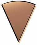
While it is true that the wedge is very similar to the inclined plane physically, engineers use this machine for slightly different purposes. The inclined plane functions to transport heavy objects over a stationary surface, while the wedge itself can move in order to move or lift objects. Therefore, the wedge is essentially an inclined plane in motion. When a wedge is moved, a forward force is converted into the outward or parting force used to separate or split material.
Even though the wedge can also be used to lift or move objects a short distance, throughout history it has been primarily utilized as a valuable cutting device. An axe is a classic example of how a wedge is used to make work easier. Can you imagine how hard it would be to cut down a tree or chop wood without an axe? Even the strongest of men pulling on a piece of timber in opposite directions could not complete the chore. Yet, generally one hefty swing of an axe will accomplish the feat with little effort.
In addition to the axe, other familiar tools such as a knife, shovel, plow and scissors all take advantage of the wedge in order to easily separate bound material. Can you think of other devices where the wedge is at work? Sometimes it is difficult to identify the wedge in the various engineering designs today because of the many different appearances it can have. It is interesting, however, when we realize where the wedge can be found in as many unfamiliar places as well, such as the hull of a ship, airplane wings, and even our front teeth!
Screw
While all six simple machines have their own distinct qualities, only the screw is able to convert a rotational force into a favorable linear force. This characteristic is desirable in many engineering applications where rotational motion is the only source of effort available to perform work, like a jet engine. Similar to the wedge, the screw (see Figure 5) is also closely related to the inclined plane since it is actually composed of an inclined plane wrapped around a cylinder. The spiraled edges around the cylindrical surface, commonly referred to as the screw threads, give the screw its ability to do work.
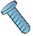
Since engineers can apply this machine to two different unrelated applications, the screw has two general classifications: the fastening screw and the lifting screw. In contrast to the wedge, which is designed with the ability to cut and separate material, the fastening screw is used to fasten and join two pieces of material together. This type of screw usually has sharp threads which cut into the parts being joined together. The materials eventually become squeezed and held together between the head of the screw and its threads. Friction from the rough threads, on the other hand, keeps the screw from working loose over time.
The lifting screw is the other type of screw, designed primarily for lifting or moving mass in a direction parallel to the axis of the screw. Since the lifting screw must rotate many times in order to advance the load a short distance, work is made easier with its help. Although it may be hard to visualize, a great example of the lifting screw is a common propeller found on a small aircraft or boat. When the propeller is spun by a rotational force provided by the engine, a linear force is created along its rotational axis to produce thrust. Aeronautical engineers have also found this tool to be exceptionally beneficial for helicopter rotors and jet engines as well.
In addition to the propeller, a spiral staircase, nut and bolt, woodscrew, auger, drill bit, worm gear, and windmill are also good examples of how the screw is applied in many helpful engineering systems today.
Lesson Background and Concepts for Teachers
It is well known that simple machines can make work easier, but exactly how much easier? The answer to this question is known as mechanical advantage, which is defined to characterize a machine's ability to lessen the burden of work. Mechanical advantage is the number of times a force exerted on a machine is multiplied by the machine, in other words, the degree to which a machine makes work easier. Recall from Lesson 1 that the mechanical advantage of all machines is defined by the general expression:
However, this expression is too general and so it is necessary to define specifically the mechanical advantage of each machine in terms of their own unique mechanics. Furthermore, only the ideal, or theoretical, mechanical advantage of each simple machine is presented in this lesson since the actual mechanical advantage cannot be determined in advance. Some of the associated activities in this unit such as Tools and Equipment, Part I, focus on both the ideal and actual mechanical advantage of a simple machine and how these values compare with one another.
Mechanical Advantage
Inclined Plane
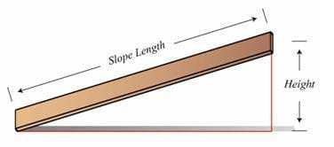
The inclined plane gains mechanical advantage by transferring some particular load over a long gradual incline rather than transporting it over a much shorter vertical path. Therefore, speaking in terms of mechanical advantage, since the path taken to raise the load is along the incline, the input distance is equal to the slope length and the output distance is the overall height of the inclined plane. In other words, by advancing the load along the length of the slope, it is ultimately raised a vertical distance equal to the height of the plane. Accordingly, the ideal mechanical advantage of the inclined plane is written as:
From this result we can easily see, as illustrated in Figure 6, that the longer the inclined plane is, the greater the mechanical advantage and the easier it is to accomplish work.
Wedge
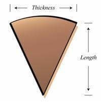
Dividing a piece of material is often a very troublesome exercise, yet a wedge can make this task become seemingly effortless. With this simple machine, mechanical advantage is gained when an input force is applied to its end and converted into a greater outward or parting force acting on the bound material. Theoretically then, if a wedge is driven into a piece of material by its full length, then the object will be forced apart by a span equal to the thickness of the wedge's end. Therefore, the input distance of a wedge is equal to its length and the output distance is equivalent to its end thickness as shown in Figure 7.
Consequently the mechanical advantage of the wedge is given by:
Using this information, engineers can design a wedge with a variable mechanical advantage by simply adjusting its physical dimensions. From a geometrical standpoint, the longer and thinner the wedge, the greater the mechanical advantage it provides.
Screw
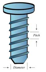
Since the screw must rotate many times to advance a load a short distance, the effort required to turn the screw is reduced and so mechanical advantage is gained. In theory, after rotating the screw by one revolution the load will advance along the screw's axis by the thread pitch, which is the axial distance from one thread groove to the next. Thus, the input distance is the circumference of the screw while the output distance is the manufactured thread pitch. So the ideal mechanical advantage of a screw is written mathematically as:
This explains why there are so many different types of screws available from the hardware store. Engineers design screws with different mechanical advantages for different job applications. Fine thread screws (lower pitch screws) have a greater mechanical advantage so they can do work with little supplied effort, while coarse thread screws (higher pitch screws) have a relatively lower mechanical advantage in order to work with a sufficient amount of effort available (see Figure 8).
After discussing each simple machine and their corresponding mechanical advantage, notice that each machine does not have a fixed mechanical advantage associated with it. Rather, each machine can be engineered to provide any desired advantage. This enables engineers to accomplish work using the easiest and most efficient way possible. Many of the associated activities in this unit expand on this concept further, where the mechanical advantage of a specific machine is intentionally increased in order to reduce the necessary effort, thereby making tough work easier and easier to do.
Associated Activities
- Tools and Equipment, Part I - In this activity, students use an inclined plane to confirm the relationship between ideal mechanical advantage and actual mechanical advantage.
Lesson Closure
Since work is defined to be simply the product of force and distance, most tasks can be accomplished in many different ways, even though the amount of work done remains the same. Simple machines help us make work easier by applying a force over a greater distance. This fundamental idea enables the inclined plane to lift heavy objects with little effort, the wedge to easily cut rigid objects in two, and the screw to multiply a rotational torque into a linear force. Engineers integrate these three machines in many useful devices today, such as stairs, highways, scissors, plows and airplanes. The mechanical advantage of a machine describes how the machine makes work easier. If the mechanical advantage of a machine is less than one, work is harder; however if the mechanical advantage is greater than one, work is easier.
Vocabulary/Definitions
complex machine: A machine that operates by combining two or more of the six simple machines.
inclined plane: A simple machine consisting of a ramp or other angled surface allowing people to lift objects using less force.
mechanical advantage: The number of times a force exerted on a machine is multiplied by the machine.
screw: A simple machine consisting of a spiral ridge wrapped around a rod or cylinder, working like an inclined plane. This machine converts a rotational force into a longitudinal force.
simple machine: The fundamental parts of any machine. Simple machines can exist on their own and are also sometimes hidden in the mechanical devices around you; a device which performs work by increasing or changing the direction of force, making work easier for people to do.
wedge: A simple machine consisting of a piece of wood or metal that is thicker at one end than the other. This machine transfers a downward force into an outward force.
work: The energy spent moving an object over a distance using force (W = Fd).
Assessment
Pre-Lesson Assessment
Question/Answer: Ask the students and discuss as a class:
- Who does more work: engineer Ed lifts a 200 lb. weight up to a height of 2 ft. and engineer Emma lifts a 50 lb. weight to a height of 8 ft.? (Answer: They both do the same amount of work, 400 ft-lbs or 542 Joules of work. Use W = Fd.)
- From the previous scenario, who did the work easier? (Answer: Engineer Emma, who used a force of only 50 lbs while engineer Ed used a force of 200 lbs.)
Post-Introduction Assessment
Voting: Ask a true/false question and have students vote by holding thumbs up for true and thumbs down for false. Count the votes and write the totals on the board. Give the right answer.
- True or False: The inclined plane has more mechanical advantage than both the wedge and screw. (Answer: False. While every simple machine provides mechanical advantage, each machine does not have a specific mechanical advantage associated with it. An engineer has the option to design an inclined plane with a mechanical advantage of either 2 or 200. Remember, an engineer may complete the same amount of work in many different ways, although some ways are easier than others.)
- True or False: The wedge and screw can be thought of as slight variations of the inclined plane. (Answer: True. The wedge is composed of two inclined planes set back to back and the screw is composed of wrapping an incline around a cylinder.)
Lesson Summary Assessment
Calculations: Have students solve mechanical advantage problems for varying shapes.
- Inclined Plane: If the slope length of an inclined plane is 9 m, and the height is 3.5 m, what is its mechanical advantage? (Answer: Mechanical Advantage= (9 m)/(3.5 m)= 2.57)
- Wedge: If the mechanical advantage of a wedge is 5, and its thickness is 0.2 m, what is its length? (Answer: Length= Mechanical Advantage*Thickness=5*0.2 m= 1 m)
- Screw: If the mechanical advantage of a screw is 1.2, and its diameter is 2 cm, what is its pitch in meters? (Answer:Pitch= (3.14*Diameter)/(Mechanical Advantage)= (3.14*0.02 m)/1.2= 0.053 m)
Discussion Question: Solicit, integrate, and summarize student responses.
- Ask the students to think about the difference between ideal mechanical advantage and actual mechanical advantage. Students should be told that only ideal mechanical advantage can be determined in advance. Ideal mechanical advantage is the advantage a machine provides under ideal circumstances or without the presence of friction. The actual mechanical advantage is determined after the input and output forces are measured and accounts for the unfavorable effect of friction in a machine. Since friction is a force which opposes motion, the actual mechanical advantage of a machine is always less than its ideal mechanical advantage, written as:
Lesson Extension Activities
Have the students form small groups of two or three. Each group is challenged to think of where the inclined plane, the wedge and the screw can be found in engineering systems today. The group who thinks of the most machines is the winning team. To get full credit, each team must state the engineering device along with the associated simple machine. Examples: Inclined plane: stairs, handicap ramp, aircraft ascent path, highway, hiking trail, slide, etc. Wedge: axe, airplane wing, knife, scissors, front teeth, ship hull, turbine blades, lawn mower, chainsaw, hand saw, etc. Screw: propeller, wood screw, bolts, helicopter rotor, jet engine, drill bits, auger, windmill, etc.
Complex Machines
[Note to teacher: This extension activity is one that should be done after all six simple machines have been introduced to students through this lesson and the lesson Levers That Lift]
A complex machine is one that operates by combining two or more simple machines together. Consider a pair of scissors. The two arms that you squeeze together are levers, while the cutting edges of the blades are sharp wedges. The scissors were a solution to a real-world problem that was made simple by breaking it down into smaller pieces. The simple machines of a lever and wedge were combined to create an engineering solution.
In groups of two, think about the following complex machines. For each complex machine, list the simple machines that have been combined and where they are found (just like the description of the scissors):
- Wheelbarrow
- Manual can opener
- Pencil sharpener
- Corkscrew
Answers:
- Wheelbarrow: The wheelbarrow itself is a 2nd class lever combined with a wheel and axle to make it roll.
- Manual can opener: The handle you rotate is a wheel and axle. The two long arms that clamp make a lever. The circular wheel that cuts the metal lid is a sharp wedge.
- Pencil sharpener: The blade that cuts and sharpens the pencil is a wedge. A screw holds the pieces together. The piece you spin is a wheel and axle.
- Corkscrew: The rotating handle at the top is a wheel and axle. The spiral metal piece that secures the cork is a screw. The sharp tip on the bottom of the spiral piece is a wedge to dig into the cork before turning. The two side arms that are pushed down are levers.
Subscribe
Get the inside scoop on all things Teach Engineering such as new site features, curriculum updates, video releases, and more by signing up for our newsletter!More Curriculum Like This

Students are introduced to three of the six simple machines used by many engineers: lever, pulley, and wheel-and-axle. In general, engineers use the lever to magnify the force applied to an object, the pulley to lift heavy loads over a vertical path, and the wheel-and-axle to magnify the torque appl...

In this lesson, students learn about work as defined by physical science and see that work is made easier through the use of simple machines. Already encountering simple machines everyday, students will learn about their widespread uses in improving everyday life.

Students explore building a pyramid, learning about the simple machine called an inclined plane. They also learn about another simple machine, the screw, and how it is used as a lifting or fastening device.

Students are introduced to the six types of simple machines — the wedge, wheel and axle, lever, inclined plane, screw, and pulley — in the context of the construction of a pyramid, gaining high-level insights into tools that have been used since ancient times and are still in use today.
References
Kahan, Peter. Motion, Forces, and Energy: Science Explorer Student Edition. Upper Saddle River, NJ: Prentice Hall. 2002.
Macaulay, David. The way things work. Boston, MA: Houghton Mifflin Company. 1988.
U.S. Department of Justice, Civil Right Division, Disability Rights Section, ADA Checklist for Polling Places, February 2004, accessed September 4, 2007. http://www.usdoj.gov/crt/ada/votingchecklist.htm
Woods, Michael, Woods, Mary. Ancient machines: from wedges to waterwheels. Minneapolis, MN: Runestone Press. 2000.
Copyright
© 2007 by Regents of the University of Colorado.Contributors
Jake Lewis; Malinda Schaefer Zarske; Janet YowellSupporting Program
Integrated Teaching and Learning Program, College of Engineering, University of Colorado BoulderAcknowledgements
The contents of these digital library curricula were developed by the Integrated Teaching and Learning Program under National Science Foundation GK-12 grant no. 0338326. However, these contents do not necessarily represent the policies of the National Science Foundation, and you should not assume endorsement by the federal government.
Last modified: January 8, 2021


User Comments & Tips