Quick Look
Grade Level: 10 (9-12)
Time Required: 15 minutes
Lesson Dependency: None
Subject Areas: Physical Science, Science and Technology
NGSS Performance Expectations:

| HS-ESS3-4 |

Summary
Students learn how to find the maximum power point (MPP) of a photovoltaic (PV) panel in order to optimize its efficiency at creating solar power. They also learn about real-world applications and technologies that use this technique, as well as Ohm's law and the power equation, which govern a PV panel's ability to produce power.Engineering Connection
PV panels are becoming an increasingly common way to generate power around the world for many different power applications. As a result, solar energy technology is an emerging energy field that provides opportunities for talented and bright engineers to make beneficial impacts on the environment while solving intriguing engineering challenges. Before attempting to design solar power systems, engineers must understand fundamental electrical laws and equations (including Ohm's law and the power equation) and how they apply to solar energy applications. By understanding the factors that affect electrical circuits and knowing how to control the elements in circuits, engineers are able to design solar power systems that operate as efficiently as possible in different environments with changing weather conditions.
Learning Objectives
After this lesson, students should be able to:
- Define maximum power point (MPP) as it applies to photovoltaic (PV) panels.
- Explain how inverters are used to maximize the efficiency of a solar power system.
- Explain Ohm's law.
- Explain the power equation.
Educational Standards
Each TeachEngineering lesson or activity is correlated to one or more K-12 science,
technology, engineering or math (STEM) educational standards.
All 100,000+ K-12 STEM standards covered in TeachEngineering are collected, maintained and packaged by the Achievement Standards Network (ASN),
a project of D2L (www.achievementstandards.org).
In the ASN, standards are hierarchically structured: first by source; e.g., by state; within source by type; e.g., science or mathematics;
within type by subtype, then by grade, etc.
Each TeachEngineering lesson or activity is correlated to one or more K-12 science, technology, engineering or math (STEM) educational standards.
All 100,000+ K-12 STEM standards covered in TeachEngineering are collected, maintained and packaged by the Achievement Standards Network (ASN), a project of D2L (www.achievementstandards.org).
In the ASN, standards are hierarchically structured: first by source; e.g., by state; within source by type; e.g., science or mathematics; within type by subtype, then by grade, etc.
NGSS: Next Generation Science Standards - Science
| NGSS Performance Expectation | ||
|---|---|---|
|
HS-ESS3-4. Evaluate or refine a technological solution that reduces impacts of human activities on natural systems. (Grades 9 - 12) Do you agree with this alignment? |
||
| Click to view other curriculum aligned to this Performance Expectation | ||
| This lesson focuses on the following Three Dimensional Learning aspects of NGSS: | ||
| Science & Engineering Practices | Disciplinary Core Ideas | Crosscutting Concepts |
| Design or refine a solution to a complex real-world problem, based on scientific knowledge, student-generated sources of evidence, prioritized criteria, and tradeoff considerations. Alignment agreement: | Scientists and engineers can make major contributions by developing technologies that produce less pollution and waste and that preclude ecosystem degradation. Alignment agreement: When evaluating solutions it is important to take into account a range of constraints including cost, safety, reliability and aesthetics and to consider social, cultural and environmental impacts.Alignment agreement: | Feedback (negative or positive) can stabilize or destabilize a system. Alignment agreement: Engineers continuously modify these technological systems by applying scientific knowledge and engineering design practices to increase benefits while decreasing costs and risks.Alignment agreement: |
International Technology and Engineering Educators Association - Technology
-
Energy resources can be renewable or nonrenewable.
(Grades
9 -
12)
More Details
Do you agree with this alignment?
-
Power systems must have a source of energy, a process, and loads.
(Grades
9 -
12)
More Details
Do you agree with this alignment?
State Standards
Colorado - Math
-
Graph linear and quadratic functions and show intercepts, maxima, and minima.
(Grades
9 -
12)
More Details
Do you agree with this alignment?
-
Solve linear equations and inequalities in one variable, including equations with coefficients represented by letters.
(Grades
9 -
12)
More Details
Do you agree with this alignment?
Colorado - Science
-
Use appropriate measurements, equations and graphs to gather, analyze, and interpret data on the quantity of energy in a system or an object
(Grades
9 -
12)
More Details
Do you agree with this alignment?
-
Evaluate the energy conversion efficiency of a variety of energy transformations
(Grades
9 -
12)
More Details
Do you agree with this alignment?
Worksheets and Attachments
Visit [www.teachengineering.org/lessons/view/cub_pveff_lesson03] to print or download.Pre-Req Knowledge
A basic understanding of electrical circuits, including voltage, current, power and resistance.
Introduction/Motivation
(In advance, make copies of the attached Fundamentals Article, which contains information used throughout this lesson, one per student or one per small group.)
Can you imagine the world without electrical power? Have any of you ever used a device that required electricity or a battery to operate? If you have, raise your hand high. That may seem like a silly question because electronics are so common in our everyday lives. It is hard to imagine someone not using electricity or batteries on a daily basis. A better question might be: Can you imagine a day with no electricity, no batteries, no electrical power at all? Think for just a moment about what your life would be like if you could not use — for an entire day — any device that relied on electrical power? Can you even count how many times a day you use an electrically-powered device?
So many electrical devices are crucial to our everyday lives, but do you realize that every device, if it uses some electrical power source, such as electricity from a wall outlet, batteries or solar panels, was designed by engineers based on two fundamental electrical equations? (Write these equations on the board or post in a prominent place in the classroom.)
Ohm's law: V = I * R
Electrical power equation: P = V * I
where:
V = voltage [volts, V]
I = current [ampere, A]
R = resistance [Ohm, Ω]
P = power [watt, W]
These two equations apply to any circuit, whether it is something as small as a battery-powered flashlight on your key chain, or a huge solar power plant with 5,000 solar panels generating renewable energy from the sun. Let's begin our endeavor as solar energy engineers by seeking to understand the basics of designing a solar power system based on these fundamental electrical equations.
Our goal is to generate as much power as possible with a given number of photovoltaic (PV) panels. Looking at the power equation, we discover that we need the highest current and voltage possible to produce the highest power. That concept seems clear enough. We can also see from Ohm's law that voltage and current are related to the resistance in a circuit. If we have no resistance (R = 0), then there will be no voltage (V = 0) and thus no power. Also, if we make our resistance really high, then the resulting current becomes very small and reduces our power output. From these basic equations we know that to maximize the power output of a solar power plant we must understand what factors affect the voltage and current in our circuit and seek to maximize them both (see the The Temperature Effect and Solar Angles and Tracking Systems lessons for more information), and we also must have a resistance in our circuit that ensures the best voltage and current combination to achieve maximum power.
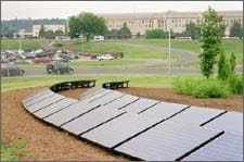
Solar power technology is still expensive when compared to other sources of power, so it is important to maximize the power output of a PV system at all times when solar energy is available. This can be a challenge because as weather conditions change (such as temperature fluctuations or varying amounts of sunlight reaching the panels), the voltage and current in the circuit change. When this happens, a new maximum power point (MPP) must be found to optimize the system power output. One cool device that engineers have designed to ensure that a solar power system continues to operate at the highest efficiency even when the weather or surrounding conditions change is called an inverter. This device does many things, but one important function of an inverter is to vary the resistance and find the MPP in a circuit. This is called maximum power point tracking (MPPT). An inverter can be hooked up to one or many PV panels at a time. For a power plant, it is less expensive to have one inverter to control a circuit with many panels. However (looking at Figure 1 or look out the window to a cloudy sky), can you think of one issue that might hinder achieving maximum efficiency if all the panels in this field were hooked up to only one MPPT inverter?
If you thought about cloud cover, you are right. When a cloud covers only a few PV panels, then those panels receive less solar radiation and operate under different circuit conditions — they have a different MPP. If only one MPPT inverter is used for the entire plant, it is impossible to achieve the maximum efficiency from each panel in this situation. It is up to engineers to decide the right balance of cost and efficiency when designing solar power plants.
(Conduct a post-introduction assessment as described in the Assessment section; have students read the attached Fundamentals Article, and write down five important facts they learned). Following the lesson students can further their understanding of these concepts by conducting the associated activity Pointing at Maximum Power for PV to identify the maximum power point by relating current, voltage and resistance.
Lesson Background and Concepts for Teachers
The I-V (Current-Voltage) and Maximum Power Point Curve
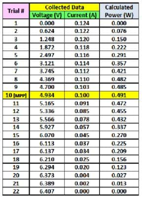
When a PV panel receives solar radiation, it produces power, the product of current and voltage. To find the highest possible power output for a panel under a certain set of conditions (amount of sunlight, temperature, etc.), the resistance in the circuit can be changed systematically by small increments, as shown in Table 1.
The values in Table 1 were obtained by using a potentiometer to vary the resistance in the PV circuit, which directly affects the voltage and current in the circuit. A potentiometer is a small device that changes the resistance with the turn of a knob. The changing resistance affects the overall power output of the panel. In this example, the short circuit current, Isc = 0.124 A (or current when V = 0), and open circuit voltage, Voc = 6.407 V (or voltage when I = 0). The MPP can also be found as the point at which the product of the current and voltage equal the greatest value. The power calculation shows that the MPP has a voltage of VMPP = 4.934, a current of IMPP = 0.100 A, with the power, P = 0.491 W.
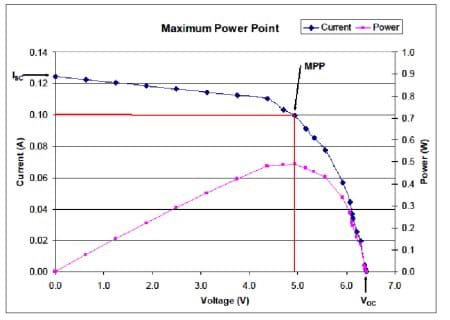
This data can be visualized more clearly in a graph. Graphing the current and voltage creates a curve that is referred to as an I-V curve. The blue line in the Figure 2 graph is an I-V curve. The current is plotted in amps (A) on the left y-axis. The voltage is plotted in volts (V) on the x-axis. On this same graph, the power for each current-voltage combination is plotted in pink. The power is plotted in watts (W) on the right y-axis. This power curve clearly shows the maximum power point. A red line identifies the voltage and current associated with the maximum power point.
Associated Activities
- Pointing at Maximum Power for PV - Pointing at Maximum Power for PV Student teams measure voltage and current output of a photovoltaic (PV) panel while varying the resistance in a connected simple circuit. Students calculate power for each resistance setting, create a graph of current vs. voltage, and identify the maximum power point (MPP).
Lesson Closure
Today, we learned about maximum power point (MPP) as it applies to photovoltaic (PV) panels. We learned about the importance of optimizing the current, voltage and resistance in a PV panel circuit, and how an inverter is used to vary the resistance and find the MPP in a circuit.
(Point to the Ohm's law and power equations on the board or posted in the classroom.) Who can explain these two equations to me? (Ask students the summary assessment questions, as listed in the Assessment section.)
Many advances in the capabilities of solar energy technology have occurred since the concept of turning sunlight into electrical energy was first discovered, but much more is waiting to be discovered and designed. Engineers are always seeking ways to improve the efficiency of solar panels and the equipment used to control their power output such as inverters. Students like you who are studying and learning today, will be the engineers who make a difference tomorrow.
Vocabulary/Definitions
efficiency: The ratio of the useful energy delivered by a dynamic system to the energy supplied to it.
I-V curve: The curve produced when the value of a panel's current is plotted with respect to different voltages, from 0 to V˅OC (I = current, in amps; V = voltage, in volts)
maximum power point (MPP): The point on a power (I-V) curve that has the highest value of the product of its corresponding voltage and current, or the highest power output.
maximum power point tracker (MPPT): A device that continually finds the MPP of a solar panel or array.
open circuit voltage (V˅OC): Voltage available from a power source in an open circuit, I = 0.
photovoltaic cell: A cell of silicone that produces a current when exposed to light.
potentiometer: A device that allows the user to vary the electrical resistances in a circuit.
short circuit current (I˅OC): Current drawn from a power source if no load is present in the circuit, V = 0.
Assessment
Pre-Lesson Assessment
Discussion Questions: Ask the students the following questions and discuss them as a class:
- What is electrical power?
- What components make up electrical power?
- What is Ohm's law?
Post Introduction Assessment
Class Discussion: Have students read the Fundamentals Article. Ask each student or group to record on a sheet of paper or in their journal five facts they learned from the article. Have each student or group write one fact on the board to be discussed as a class.
Lesson Summary Assessment
Class Discussion: Ask the students the following questions and discuss as a class:
- Why is an inverter important? (Answer: An inverter can act as a MPPT and measure the power output of a circuit at different resistances to find the MPP in different weather conditions. Note: An inverter also serves other important functions that are not discussed in this lesson.)
- Why is it important to continually check the MPP of solar panels in a solar power plant? (Answer: Changing weather conditions can cause the conditions in the circuit to change. Continually finding the MPP ensures the panels are producing the most power possible at all times so the plant is as efficient as possible at converting sunlight into electrical power. This is especially important for solar power plants, to make them as cost effective as possible.)
Additional Multimedia Support
A great introduction to circuits and Ohm's law: http://www.allaboutcircuits.com/vol_1/chpt_2/1.html
Subscribe
Get the inside scoop on all things Teach Engineering such as new site features, curriculum updates, video releases, and more by signing up for our newsletter!More Curriculum Like This

Students explore how the efficiency of a solar photovoltaic (PV) panel is affected by the ambient temperature. They learn how engineers predict the power output of a PV panel at different temperatures and examine some real-world engineering applications used to control the temperature of PV panels.

Students examine how the power output of a photovoltaic (PV) solar panel is affected by temperature changes. Using a 100-watt lamp and a small PV panel connected to a digital multimeter, teams vary the temperature of the panel and record the resulting voltage output.

Students learn about the daily and annual cycles of solar angles used in power calculations to maximize photovoltaic power generation. They gain an overview of solar tracking systems that improve PV panel efficiency by following the sun through the sky.

Students learn about current electricity and necessary conditions for the existence of an electric current. Students construct a simple electric circuit and a galvanic cell to help them understand voltage, current and resistance.
Copyright
© 2009 by Regents of the University of Colorado.Contributors
Jack Baum, Stephen Johnson, William Surles, Abby Watrous, Malinda Schaefer Zarske (This high school curriculum was originally created as a class project by engineering students in a Building Systems Program course at CU-Boulder.)Supporting Program
Integrated Teaching and Learning Program, College of Engineering and Applied Science, University of Colorado BoulderAcknowledgements
The contents of this digital library curriculum were developed under a grant from the Fund for the Improvement of Postsecondary Education (FIPSE), U.S. Department of Education and National Science Foundation GK-12 grant no. 0338326. However, these contents do not necessarily represent the policies of the Department of Education or National Science Foundation, and you should not assume endorsement by the federal government.
Last modified: June 18, 2019


User Comments & Tips