Quick Look
Grade Level: 9 (9-12)
Time Required: 1 hours 30 minutes
(two 45-minute periods or one 90-minute block)
Expendable Cost/Group: US $1.00
Group Size: 3
Activity Dependency: None
Subject Areas: Geometry, Physical Science, Problem Solving, Science and Technology
NGSS Performance Expectations:

| HS-ETS1-1 |
| HS-ETS1-3 |
Summary
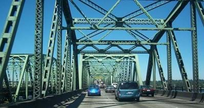
Working as engineering teams, students use the engineering design process to plan, create, and test model bridges using plastic drinking straws and tape as their construction materials. Their goal is to build the strongest bridge with a truss pattern of their design while meeting the design criteria and constraints. They experiment with different geometric shapes and determine how shapes affect the strength of materials.Engineering Connection
Engineers brainstorm, design, and test solutions to real-life problems. For example, civil and structural engineers who design new buildings are challenged to create homes, buildings, and skyscrapers that are both eco-friendly and structurally sound. To design bridges, engineers perform a careful analysis of bridge geometries and the anticipated applied loads so they can determine the exact place of the reaction forces. Engineers also consider the most effective materials to achieve a balance of tension and compression. Engineers determine the bridge type, design, and materials; analyze site conditions, and geologic and environmental factors; and establish detailed design plans and budget/funding schedules.
Learning Objectives
After this activity, students should be able to:
- Describe and design model truss bridges.
- Identify effective geometric shapes used in bridge design.
- Identify several factors that engineers consider when designing bridges.
Educational Standards
Each TeachEngineering lesson or activity is correlated to one or more K-12 science,
technology, engineering or math (STEM) educational standards.
All 100,000+ K-12 STEM standards covered in TeachEngineering are collected, maintained and packaged by the Achievement Standards Network (ASN),
a project of D2L (www.achievementstandards.org).
In the ASN, standards are hierarchically structured: first by source; e.g., by state; within source by type; e.g., science or mathematics;
within type by subtype, then by grade, etc.
Each TeachEngineering lesson or activity is correlated to one or more K-12 science, technology, engineering or math (STEM) educational standards.
All 100,000+ K-12 STEM standards covered in TeachEngineering are collected, maintained and packaged by the Achievement Standards Network (ASN), a project of D2L (www.achievementstandards.org).
In the ASN, standards are hierarchically structured: first by source; e.g., by state; within source by type; e.g., science or mathematics; within type by subtype, then by grade, etc.
NGSS: Next Generation Science Standards - Science
| NGSS Performance Expectation | ||
|---|---|---|
|
HS-ETS1-1. Analyze a major global challenge to specify qualitative and quantitative criteria and constraints for solutions that account for societal needs and wants. (Grades 9 - 12) Do you agree with this alignment? |
||
| Click to view other curriculum aligned to this Performance Expectation | ||
| This activity focuses on the following Three Dimensional Learning aspects of NGSS: | ||
| Science & Engineering Practices | Disciplinary Core Ideas | Crosscutting Concepts |
| Analyze complex real-world problems by specifying criteria and constraints for successful solutions. Alignment agreement: | Criteria and constraints also include satisfying any requirements set by society, such as taking issues of risk mitigation into account, and they should be quantified to the extent possible and stated in such a way that one can tell if a given design meets them. Alignment agreement: Humanity faces major global challenges today, such as the need for supplies of clean water and food or for energy sources that minimize pollution, which can be addressed through engineering. These global challenges also may have manifestations in local communities.Alignment agreement: | New technologies can have deep impacts on society and the environment, including some that were not anticipated. Analysis of costs and benefits is a critical aspect of decisions about technology. Alignment agreement: |
| NGSS Performance Expectation | ||
|---|---|---|
|
HS-ETS1-3. Evaluate a solution to a complex real-world problem based on prioritized criteria and trade-offs that account for a range of constraints, including cost, safety, reliability, and aesthetics, as well as possible social, cultural, and environmental impacts. (Grades 9 - 12) Do you agree with this alignment? |
||
| Click to view other curriculum aligned to this Performance Expectation | ||
| This activity focuses on the following Three Dimensional Learning aspects of NGSS: | ||
| Science & Engineering Practices | Disciplinary Core Ideas | Crosscutting Concepts |
| Evaluate a solution to a complex real-world problem, based on scientific knowledge, student-generated sources of evidence, prioritized criteria, and tradeoff considerations. Alignment agreement: | When evaluating solutions it is important to take into account a range of constraints including cost, safety, reliability and aesthetics and to consider social, cultural and environmental impacts. Alignment agreement: | New technologies can have deep impacts on society and the environment, including some that were not anticipated. Analysis of costs and benefits is a critical aspect of decisions about technology. Alignment agreement: |
International Technology and Engineering Educators Association - Technology
-
Illustrate principles, elements, and factors of design.
(Grades
9 -
12)
More Details
Do you agree with this alignment?
Materials List
Each team needs:
- 20 plastic drinking straws (not the bendy type)
- Scotch or masking tape
- scissors
- measuring stick or ruler
- 1 sheet of paper
- pencil or marker
- Straw Bridges Worksheet, one per student
For the entire class to share:
- laptop and projector, for showing the Straw Bridges Presentation
- pennies, weights, or various hardcover and softcover books to use as weights
- small paper cup (or similar, to hold the pennies/weights during testing)
- 2 desks or tables of equal height from the floor, to serve as the testing station
- scale, one that can weigh a minimum of 3 lbs. (~1.4 kg)
Worksheets and Attachments
Visit [www.teachengineering.org/activities/view/ced-2679-straw-bridges-design-challenge-activity] to print or download.Introduction/Motivation
Today, we are going to act as teams of structural engineers making bridge models using the engineering design process. We have been hired by a city to design and create a bridge to cross one of the local rivers. However, the city does not want the bridge to affect the fish population in the river below it. Engineers must always consider the design objective when creating models.
Today our design objective is to make a bridge that spans the river and supports the most weight. Your bridge design must span a distance of 10 inches (25 cm), which means that the bridge must measure longer than that so it can rest on the abutments on each side of the river.
To simulate the load of the cars, your bridge must have a place to securely hold a small cup in the center of the span. Pennies will be added to the cup until the bridge collapses. That amount of pennies and its cup will be weighed.
To demonstrate environmental limitations on the design, no part of the bridge may touch the "water" (or bottom of the wooden support structure) and the bridge cannot be taped to the wooden support structure.
Another design constraint to consider is to limit the types or amounts of materials. While you can cut your straws to any length you want, you will not be given any additional (or replacement) straws even if you accidentally cut them to lengths you don't want. Another point to make: A bundle of straws taped together does not satisfy the "spirit" of this bridge-building activity. However, it is not necessary to have bridges look as if small cars could go over them.
Engineers often have many design constraints or limitations that are part of their job assignments. Today, our design constraints not only include environmental and weight constraints but also limited budget and materials using straws and tape as our construction materials. In addition, you will have time constraints of two class periods to complete this design challenge. Let’s get started!
Procedure
Background
After the Industrial Revolution, bridges became more and more sophisticated as iron and steel became more available. By using iron and steel, engineers could design bridges capable of supporting larger loads and spanning greater distances, making it possible to link cities and communities through shorter, more direct routes and crossing obstacles such as waterways or other natural features that had previously blocked passage.
There are many different types of bridges: beam, truss, cantilever, arch, suspension, and cable-stayed (see Figure 1).
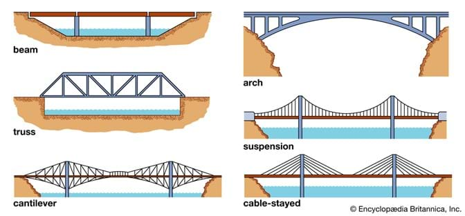
Beam and truss bridges: Beam bridges are the simplest and least expensive type of bridge to build. The simplest beam bridges consist of a horizontal beam that is supported on each end by columns or piers. The weight of the beam and any additional load on the bridge is transferred directly to the piers. However, the beam itself must be able to support its own weight and loads between the piers. When a load pushes down on the beam, the top portion of the beam is pushed together by a compressive force while a tensile force stretches the lower portion. The farther apart the supports or piers, the weaker a beam bridge becomes. For larger beam bridges designed for heavy car and railroad traffic, the beams are substituted by simple trusses, or triangular units, which are more economical than solid beams. Engineers have used many different truss patterns in bridges. Therefore, most beam bridges rarely span more than 200 feet (61m), however, old truss bridges crossing major rivers are often as long as 500-600 feet (152-183m), not including end supports such as piers.

Arch bridges: Arch bridges are the easiest type of bridge to recognize. They are one of the oldest types of bridges and have extraordinary natural strength. Instead of pushing straight down as beam bridges do, the weight of the arch bridge and any additional load on the bridge is carried outward along the curve of the arch to the supports at each end. These supports are called abutments. Abutments distribute the load from the bridge and keep the ends of the bridge from spreading out. The Romans were masters of the arch bridge. Many of their arch bridges used little or no mortar, or "glue," to hold the stones together. The goal of an arch bridge is to carry all loads in compression, without any tensile loads present. The stones in the structures stay together by the sheer force of their weight and the compression transferred between them. The size of the arch, or the amount of curvature, has a major effect on the effectiveness of this type of bridge. Sometimes, in very large arch bridges, the arch is often reduced in size or flattened down, which results in significant tensile forces that must be factored into the design. Most modern arch bridges span between 100-1,500 feet (30-457m).
Suspension Bridges: Two categories of suspension bridges are: modern suspension bridges and cable-stayed bridges. Modern suspension bridges are characterized by an M-shaped cable pattern. Cables are strung over two towers and then anchored on both ends. The roadway is suspended from the cables by thinner cables or rods. The roadway's weight and any additional load are transferred to the cables, creating a tension force in the cables. The cables then transfer their force to the towers and anchors. Typical modern suspension bridges span distances from 2,000 to 7,000 feet (610-2,134m). Cable-stayed bridges are characterized by an A-shaped cable pattern. Cables are anchored directly to the towers and eliminate the need for an anchorage system. The same tensile and compressive forces are seen in a cable-stayed bridge as they are in a modern suspension bridge. Typical cable-stayed bridges span distances from 500 to 3,000 feet (152-914m), fast becoming the bridge of choice for medium-length spans.
Activity summary for teacher
In this design challenge, student teams will work through the complete engineering design process, including at least one iteration to improve their designs.
- Ask. Based on the introduction/motivation, students should answer the following in their Straw Bridges Worksheet:
- What problem are we trying to solve in this activity?
- What are the constraints for this activity?
- Research. After the teacher demo and the slides about truss bridges, students should answer the following in their Straw Bridges Worksheet:
- What did we learn about truss bridges?
- Imagine. Based on the problem we are trying to solve (Ask), the constraints for the project (Ask), and the info gained about truss bridges (Research), students individually brainstorm ideas to build their bridge, including which materials will be used and where in their Straw Bridges worksheet:
- Plan. Together, all individuals share their brainstormed ideas (Imagine). Once all ideas are shared, the team picks one design (or modifies one design) that they will prototype. Each team member sketches this team design in their Straw Bridges Worksheet:
- Create. Going off the chosen plan sketched on their worksheets (Plan), the team works together to build the chosen bridge design.
- Test. Once the design is complete (Create), each team tests its bridge to failure. Each team should record the weight of the cup and pennies at failure. (This is the value they want to improve upon in their next iteration.)
- Improve. Based on their research, plans, and tests, each team chooses and sketches out an improved design the following in their Straw Bridges Worksheet. Once they have an updated and improved sketch, each team gets another 20 straws from which they can improve their bridge design. (Note: teams cannot reuse their previous bridge structures, trusses, etc.) The team needs to build a brand new bridge which they then test to failure, recording the weight of the cup and pennies at failure.
Before the Activity
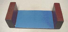
- For bridge testing, make a wooden support structure (see Figure 5; optional), or place two desks ~10 inches (25 cm) apart.
- Gather materials and make copies of the Straw Bridges Worksheet for each student.
- Have the Straw Bridges Presentation ready to show.
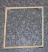
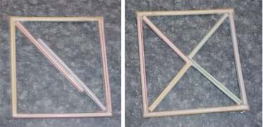
- Make example square and triangle shapes with tape and straws as shown in Figure 6 to be used in a teacher demonstration.
With the Students
DAY 1
- (5 min) Introduction to Activity
- Hand out one Straw Bridges Worksheet to each student.
- Read the Introduction/Motivation section aloud.
- Organize the students into groups of three.
- Students should answer the first two questions in the Straw Bridges Worksheet: In your own words, what problem are you trying to solve in this activity? What are the constraints for this activity?
- (10 min) Research: Discuss and demo truss bridges with students.
- Ask students to vote by a show of hands to the following question, "Which shape is more stable, triangles or squares?" Tally their responses and write the totals on the classroom board.
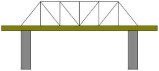
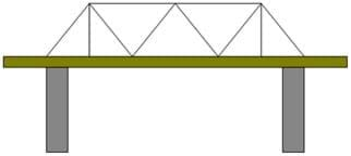
- Explain with visual demonstrations that squares are less stable than triangles. Do this by showing example straw shapes similar to those in Figures 6 and 7. Stand the shapes up on a desk and push down on the top of them. With very little force applied, the open square shape twists, while the square shape composed of inner triangles withstands much more force.
- Show students images of truss bridges in the Straw Bridges Presentation.
- Students should take notes on their Straw Bridges Worksheet about what they learned about truss bridges.
- (10 min) Brainstorm/Plan
- Inform students of the following design constraints:
- bridge must be at least 10 inches (25 cm) in length and able to span an 8-inch (20 cm) gap
- bridge must be able to securely hold gradually added weight placed in its center until it fails (begins to bend)
- bridge must incorporate a truss design
- bridge must be made of 20 (or fewer) straws
- teams may not receive any replacement straws
- bridge may not be taped to the desk
- Direct teams to brainstorm design ideas for their bridges and record and sketch their ideas on the Straw Bridges Worksheet. Advise students to carefully plan out their bridges since they will not receive any replacement materials.
- After every team member has presented their ideas to the team, have the teams each decide on one bridge to build. They should sketch this final design on their Straw Bridges Worksheet, indicating which materials they will use and where.
- (15 min) Give teams 20 minutes to create and test their bridges. Make sure teams make note of what worked and what didn't with their design on the Straw Bridges Worksheet.
- Students should store their bridge prototype with the teacher or somewhere in the classroom.
DAY 2
- (5 min) Set up activity
- To each team, pass out another 20 straws, scotch tape, scissors, and a ruler. Remind students that they are teams of engineers making model bridges using straws and tape as their construction materials. Each team needs to think carefully about what their design will look like. Figure 7 shows an example of a straw-bridge design.
- (15 min) Let teams build their improved bridges.
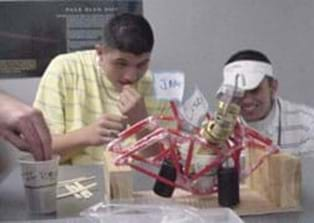
- (20 min) Before strength testing the bridges, ask each team to predict how much weight you think will make your bridge collapse. Record predictions on the board. Place each bridge on the wooden support structure (see Figure 7). Position a small paper cup on the bridge at the center of the span; do not place the cup at any other location. Gradually fill the cup with pennies until the bridge collapses or the cup falls off (see Figure 8). Weigh the cup and the pennies on the balance. Make a note of this weight, and record it on the board next to its prediction. Repeat to test all bridges. Note, it may be helpful to add a lot of pennies quickly at first until it appears that the bridge is beginning to fail. At that point, add fewer pennies at a time, more carefully and slowly. The winning bridge design is the one that supports the most weight while meeting the design criteria and constraints.
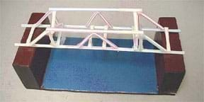
Figure 8. Example straw bridge design (Howe-Kingpost) placed on a wooden support structure for strength testing. - (5 min) Conclude by leading a class discussion of the bridge strength testing results. How would they improve their bridge design? Have students from each engineering team describe what they would do to make their bridges stronger. Other questions to think about:
- Which bridge design held the most weight?
- Which part of your bridge gave out first? Why?
- How would you improve your bridge design?
- How would you change your design if you had to span a 20-inch (51-cm) gap using the same materials?
Vocabulary/Definitions
abutment: A mass, as of masonry, receiving the arch, beam, truss, etc., at each end of a bridge.
beam: A long, rigid, horizontal support member of a structure.
beam bridge: A bridge that consists of beams supported by columns (piers, towers).
column: A long, rigid, vertical (upright) support member of a structure.
compression: A pushing force that tends to shorten objects.
deck: The "top" of the bridge on which we drive or walk.
design: To form or conceive in the mind. To make drawings, sketches or plans for a work. To design a new product. To design an improved process.
engineer: A person who applies their understanding of science and mathematics to creating things for the benefit of humanity and our world.
model: A representation of something, sometimes on a smaller scale. (verb) To make or construct something to help visualize or learn about something else.
span: The length of a bridge between two piers.
tension: A pulling or stretching force that tends to lengthen objects.
truss: A structural frame based on the geometric rigidity of the triangle and composed of straight members.
Assessment
Pre-Activity Assessment
Voting & Demo: Ask students to vote by a show of hands their opinions to the following question. Tally the votes and write the totals on the classroom board.
- Which shape is more stable: triangles or squares? (Explain with visual demonstrations that squares are less stable than triangles. Stand some example tape and straw shapes [see Figure 6] on a desk and push down on the top of them. With very little force applied, the empty square shape twists, while the square shape composed of inner triangles withstands much more force.)
Activity Embedded (Formative) Assessment
Prediction: Before testing, ask teams to predict how much weight will collapse their bridges. Record predictions on the board.
Post-Activity (Summative) Assessment
Re-Engineering: Ask students how they might improve their bridge designs, and have them sketch or test their ideas.
Making Sense Assessment: Have students reflect on the science concepts they explored and/or the science and engineering skills they used by completing the Making Sense Assessment.
Safety Issues
Remind students of scissor safety rules.
Troubleshooting Tips
- Use plastic straws that are not the flexible or "bendy neck" type. If only flexible-type straws are available, cut off the straw ends that contain the flexible sections. Since this reduces the straw length, give students 25 straws per team.
- Be eco-friendly, instead of plastic straws make "paper straws" using newspaper or letter-sized scrap paper rolled into tubes lengthwise and secured with limited amounts of tape.
- Using a scale to calculate the weight of the pennies in the cup is a quick method to determine how much weight each straw bridge held before it collapsed. If a scale is unavailable, count the number of pennies for weight comparison.
- If rulers are unavailable, measure the span by marking its width on another piece of paper as a handy reference. Or, explain how students can obtain simple measurements using full sheets of copy paper (8 ½ x 11 inches). For example, with a 10-inch span, it would be desirable to make the bridge about 11 inches or equal to the longer dimension of the paper.
Activity Extensions
- Do the "Bridging Gap Lesson" on TeachEngineering and then have students design, build, and test other bridge types and compare them to how their Truss bridge design performed.
- The free "Bridge Designer" software simulator enables students to model, test, and optimize bridge designs based on realistic specifications, constraints, and performance criteria.
- Include instruction on sketching 2D and 3D engineering designs using the "Drawing Designs in Detail" activity from TeachEngineering.
Additional Multimedia Support
Watch the "Collapse of Galloping Gertie (the Tacoma Narrows Bridge" video to spark a class discussion about the importance of the engineering design process.
Subscribe
Get the inside scoop on all things Teach Engineering such as new site features, curriculum updates, video releases, and more by signing up for our newsletter!References
Original TeachEngineering activity:
https://www.teachengineering.org/activities/view/cub_brid_lesson01_activity2
TeachEngineering YouTube video of activity:
https://www.youtube.com/channel/UCpRCG3gGtWqieJe-LGmi93w
Other helpful TeachEngineering bridge curricula:
https://www.teachengineering.org/curricularunits/view/cub_brid_curricularunit
https://www.teachengineering.org/activities/view/cub_brid_lesson01_activity1
Copyright
© 2022 by Regents of the University of ColoradoContributors
Jonathan S. Goode; Joe Friedrichsen; Natalie Mach; Chris Valenti; Denali Lander; Denise W. Carlson; Malinda Schaefer Zarske; Jennifer Taylor; Ellen ParrishSupporting Program
Integrated Teaching and Learning Program, College of Engineering, University of Colorado BoulderAcknowledgements
This curriculum was developed under National Science Foundation grant numbers 1941524 and 1941701. Any opinions, findings, and conclusions, or recommendations expressed in this material are those of the authors and do not necessarily reflect the views of the National Science Foundation.
Last modified: October 14, 2024



User Comments & Tips