
Quick Look
Grade Level: 6 (4-6)
Time Required: 6 hours
(Takes six hours of class time; see note in Procedure section)
Expendable Cost/Group: US $5.00 The activity also uses some non-expendable (reusable) items; see the Materials List for details.
Group Size: 3
Activity Dependency: None
Subject Areas: Science and Technology
NGSS Performance Expectations:

| 3-5-ETS1-1 |
| 3-5-ETS1-2 |
| 3-5-ETS1-3 |
| MS-ETS1-1 |
| MS-ETS1-2 |
| MS-ETS1-4 |
Quick Look

- Grade Level:
- 6 (4 – 6)
- Time Required:
- 6 hours
(Takes six hours of class time; see note in Procedure section)
- Group Size:
- 3
- Subject Areas:
-
Science and Technology -
NGSS Performance Expectations:
3-5-ETS1-1 3-5-ETS1-2 3-5-ETS1-3 MS-ETS1-1 MS-ETS1-2 MS-ETS1-4
Summary
Students act as structural engineers and learn about forces and load distributions as they follow the steps of the engineering design process to design and build small-scale bridges using wooden tongue depressors and glue. Teams brainstorm ideas that meet the size and material design constraints and create prototype bridges of the most promising solutions. They test their bridges to see how much weight they can hold until they break and then determine which have the highest strength-to-weight ratios. They examine the prototype failures to identify future improvements. This activity is part of a unit in which multiple activities are brought together for an all-day school/multi-school concluding “engineering field day” competition.
Engineering Connection
Structural engineering is one of the oldest engineering disciplines. Through this classic introduction to engineering activity, students gain an understanding of some of the challenges faced by engineers whose designs must protect public safety, such as bridges like the Golden Gate Bridge that thousands of people depend upon every day. Students experience the engineering design process to achieve effective designs, creating and testing prototype bridges to failure. They also experience the use of scale models in engineering to study how the forces and loads acting on bridges (or any structures) can result in damage. Also like real-world engineers, students analyze their bridge designs by calculating strength-to-weight ratios as a measure of structural efficiency.
Learning Objectives
After this activity, students should be able to:
- Apply and explain the use of the engineering design process to design a bridge with given size limitations.
- Calculate the strength-to-weight ratio of their final designs.
- Explain how tension and compression forces act on a bridge support when a load is applied.
Educational Standards
Each Teach Engineering lesson or activity is correlated to one or more K-12 science,
technology, engineering or math (STEM) educational standards.
All 100,000+ K-12 STEM standards covered in Teach Engineering are collected, maintained and packaged by the Achievement Standards Network (ASN),
a project of D2L (www.achievementstandards.org).
In the ASN, standards are hierarchically structured: first by source; e.g., by state; within source by type; e.g., science or mathematics;
within type by subtype, then by grade, etc.
Each Teach Engineering lesson or activity is correlated to one or more K-12 science, technology, engineering or math (STEM) educational standards.
All 100,000+ K-12 STEM standards covered in Teach Engineering are collected, maintained and packaged by the Achievement Standards Network (ASN), a project of D2L (www.achievementstandards.org).
In the ASN, standards are hierarchically structured: first by source; e.g., by state; within source by type; e.g., science or mathematics; within type by subtype, then by grade, etc.
NGSS: Next Generation Science Standards - Science
| NGSS Performance Expectation | ||
|---|---|---|
|
3-5-ETS1-1. Define a simple design problem reflecting a need or a want that includes specified criteria for success and constraints on materials, time, or cost. (Grades 3 - 5) Do you agree with this alignment? |
||
| Click to view other curriculum aligned to this Performance Expectation | ||
| This activity focuses on the following Three Dimensional Learning aspects of NGSS: | ||
| Science & Engineering Practices | Disciplinary Core Ideas | Crosscutting Concepts |
| Define a simple design problem that can be solved through the development of an object, tool, process, or system and includes several criteria for success and constraints on materials, time, or cost. Alignment agreement: | Possible solutions to a problem are limited by available materials and resources (constraints). The success of a designed solution is determined by considering the desired features of a solution (criteria). Different proposals for solutions can be compared on the basis of how well each one meets the specified criteria for success or how well each takes the constraints into account. Alignment agreement: | People's needs and wants change over time, as do their demands for new and improved technologies. Alignment agreement: |
| NGSS Performance Expectation | ||
|---|---|---|
|
3-5-ETS1-2. Generate and compare multiple possible solutions to a problem based on how well each is likely to meet the criteria and constraints of the problem. (Grades 3 - 5) Do you agree with this alignment? |
||
| Click to view other curriculum aligned to this Performance Expectation | ||
| This activity focuses on the following Three Dimensional Learning aspects of NGSS: | ||
| Science & Engineering Practices | Disciplinary Core Ideas | Crosscutting Concepts |
| Generate and compare multiple solutions to a problem based on how well they meet the criteria and constraints of the design problem. Alignment agreement: | Research on a problem should be carried out before beginning to design a solution. Testing a solution involves investigating how well it performs under a range of likely conditions. Alignment agreement: At whatever stage, communicating with peers about proposed solutions is an important part of the design process, and shared ideas can lead to improved designs.Alignment agreement: | Engineers improve existing technologies or develop new ones to increase their benefits, to decrease known risks, and to meet societal demands. Alignment agreement: |
| NGSS Performance Expectation | ||
|---|---|---|
|
3-5-ETS1-3. Plan and carry out fair tests in which variables are controlled and failure points are considered to identify aspects of a model or prototype that can be improved. (Grades 3 - 5) Do you agree with this alignment? |
||
| Click to view other curriculum aligned to this Performance Expectation | ||
| This activity focuses on the following Three Dimensional Learning aspects of NGSS: | ||
| Science & Engineering Practices | Disciplinary Core Ideas | Crosscutting Concepts |
| Plan and conduct an investigation collaboratively to produce data to serve as the basis for evidence, using fair tests in which variables are controlled and the number of trials considered. Alignment agreement: | Tests are often designed to identify failure points or difficulties, which suggest the elements of the design that need to be improved. Alignment agreement: Different solutions need to be tested in order to determine which of them best solves the problem, given the criteria and the constraints.Alignment agreement: | |
| NGSS Performance Expectation | ||
|---|---|---|
|
MS-ETS1-1. Define the criteria and constraints of a design problem with sufficient precision to ensure a successful solution, taking into account relevant scientific principles and potential impacts on people and the natural environment that may limit possible solutions. (Grades 6 - 8) Do you agree with this alignment? |
||
| Click to view other curriculum aligned to this Performance Expectation | ||
| This activity focuses on the following Three Dimensional Learning aspects of NGSS: | ||
| Science & Engineering Practices | Disciplinary Core Ideas | Crosscutting Concepts |
| Define a design problem that can be solved through the development of an object, tool, process or system and includes multiple criteria and constraints, including scientific knowledge that may limit possible solutions. Alignment agreement: | The more precisely a design task's criteria and constraints can be defined, the more likely it is that the designed solution will be successful. Specification of constraints includes consideration of scientific principles and other relevant knowledge that is likely to limit possible solutions. Alignment agreement: | All human activity draws on natural resources and has both short and long-term consequences, positive as well as negative, for the health of people and the natural environment. Alignment agreement: The uses of technologies and any limitations on their use are driven by individual or societal needs, desires, and values; by the findings of scientific research; and by differences in such factors as climate, natural resources, and economic conditions.Alignment agreement: |
| NGSS Performance Expectation | ||
|---|---|---|
|
MS-ETS1-2. Evaluate competing design solutions using a systematic process to determine how well they meet the criteria and constraints of the problem. (Grades 6 - 8) Do you agree with this alignment? |
||
| Click to view other curriculum aligned to this Performance Expectation | ||
| This activity focuses on the following Three Dimensional Learning aspects of NGSS: | ||
| Science & Engineering Practices | Disciplinary Core Ideas | Crosscutting Concepts |
| Evaluate competing design solutions based on jointly developed and agreed-upon design criteria. Alignment agreement: | There are systematic processes for evaluating solutions with respect to how well they meet the criteria and constraints of a problem. Alignment agreement: | |
| NGSS Performance Expectation | ||
|---|---|---|
|
MS-ETS1-4. Develop a model to generate data for iterative testing and modification of a proposed object, tool, or process such that an optimal design can be achieved. (Grades 6 - 8) Do you agree with this alignment? |
||
| Click to view other curriculum aligned to this Performance Expectation | ||
| This activity focuses on the following Three Dimensional Learning aspects of NGSS: | ||
| Science & Engineering Practices | Disciplinary Core Ideas | Crosscutting Concepts |
| Develop a model to generate data to test ideas about designed systems, including those representing inputs and outputs. Alignment agreement: | Models of all kinds are important for testing solutions. Alignment agreement: The iterative process of testing the most promising solutions and modifying what is proposed on the basis of the test results leads to greater refinement and ultimately to an optimal solution.Alignment agreement: | |
Common Core State Standards - Math
-
Understand ratio concepts and use ratio reasoning to solve problems.
(Grade
6)
More Details
Do you agree with this alignment?
-
Understand the concept of a ratio and use ratio language to describe a ratio relationship between two quantities.
(Grade
6)
More Details
Do you agree with this alignment?
International Technology and Engineering Educators Association - Technology
-
Models are used to communicate and test design ideas and processes.
(Grades
3 -
5)
More Details
Do you agree with this alignment?
-
Invention and innovation are creative ways to turn ideas into real things.
(Grades
3 -
5)
More Details
Do you agree with this alignment?
-
The process of experimentation, which is common in science, can also be used to solve technological problems.
(Grades
3 -
5)
More Details
Do you agree with this alignment?
-
Apply the technology and engineering design process.
(Grades
3 -
5)
More Details
Do you agree with this alignment?
-
Illustrate that there are multiple approaches to design.
(Grades
3 -
5)
More Details
Do you agree with this alignment?
-
Evaluate designs based on criteria, constraints, and standards.
(Grades
3 -
5)
More Details
Do you agree with this alignment?
-
There is no perfect design.
(Grades
6 -
8)
More Details
Do you agree with this alignment?
-
Requirements for design are made up of criteria and constraints.
(Grades
6 -
8)
More Details
Do you agree with this alignment?
-
Design involves a set of steps, which can be performed in different sequences and repeated as needed.
(Grades
6 -
8)
More Details
Do you agree with this alignment?
-
Brainstorming is a group problem-solving design process in which each person in the group presents his or her ideas in an open forum.
(Grades
6 -
8)
More Details
Do you agree with this alignment?
-
Some technological problems are best solved through experimentation.
(Grades
6 -
8)
More Details
Do you agree with this alignment?
-
Apply the technology and engineering design process.
(Grades
6 -
8)
More Details
Do you agree with this alignment?
-
Create solutions to problems by identifying and applying human factors in design.
(Grades
6 -
8)
More Details
Do you agree with this alignment?
-
Analyze how an invention or innovation was influenced by its historical context.
(Grades
6 -
8)
More Details
Do you agree with this alignment?
-
Evaluate the strengths and weaknesses of different design solutions.
(Grades
6 -
8)
More Details
Do you agree with this alignment?
-
Make two-dimensional and three-dimensional representations of the designed solution.
(Grades
6 -
8)
More Details
Do you agree with this alignment?
State Standards
California - Math
-
Understand ratio concepts and use ratio reasoning to solve problems.
(Grade
6)
More Details
Do you agree with this alignment?
-
Understand the concept of a ratio and use ratio language to describe a ratio relationship between two quantities.
(Grade
6)
More Details
Do you agree with this alignment?
California - Science
-
Generate and compare multiple possible solutions to a problem based on how well each is likely to meet the criteria and constraints of the problem.
(Grades
3 -
5)
More Details
Do you agree with this alignment?
-
Define a simple design problem reflecting a need or a want that includes specified criteria for success and constraints on materials, time, or cost.
(Grades
3 -
5)
More Details
Do you agree with this alignment?
-
Plan and carry out fair tests in which variables are controlled and failure points are considered to identify aspects of a model or prototype that can be improved.
(Grades
3 -
5)
More Details
Do you agree with this alignment?
-
Define the criteria and constraints of a design problem with sufficient precision to ensure a successful solution, taking into account relevant scientific principles and potential impacts on people and the natural environment that may limit possible solutions.
(Grades
6 -
8)
More Details
Do you agree with this alignment?
-
Develop a model to generate data for iterative testing and modification of a proposed object, tool, or process such that an optimal design can be achieved.
(Grades
6 -
8)
More Details
Do you agree with this alignment?
-
Evaluate competing design solutions using a systematic process to determine how well they meet the criteria and constraints of the problem.
(Grades
6 -
8)
More Details
Do you agree with this alignment?
Materials List
Each group needs:
- 100 wooden tongue depressors or craft sticks
- Elmer's white school glue (NOT wood glue)
- ruler
- paper and pencil, to sketch and re-sketch bridge designs
- Pre-Activity Quiz, one per student
- Mission Possible Activity Worksheet, one per student
- Post-Activity Quiz, one per student
- computer with Internet connection, for research
- safety glasses, one pair per student, to use during testing
To share with the entire class:
- (optional) 8 x 10-inch printouts of a few broken bridges from around the world, such as the four pictured in Broken Bridge Photos Visual Aid, slipped into a manila envelope, for the activity introduction
- binder clips (clamp-style paper clips), used to clamp together bridges while drying
- small hand saws
- a way to test bridge strength, such as science lab hook masses or a hanging bucket with rocks, sand or other weights, with the bridge spanning a gap between two tables placed some distance apart; alternatively, use bridge-breaker equipment if available
- scale
- calculator
- (optional) camera
Worksheets and Attachments
Visit [www.teachengineering.org/activities/view/ucd_bridge_activity1] to print or download.Pre-Req Knowledge
A familiarity with the engineering design process and calculating ratios.
Introduction/Motivation
(Deliver the activity introduction as a mission assignment, similar to how it is done in the Mission Impossible television series and movies. Be ready to show class some photographs of collapsed bridges from around the world, such as the four provided in Broken Bridge Photos Visual Aid.)
Good morning, class.
We have received several images from around the world showing bridge failure. (Show students the photos and pass them around the class.) Here's one in Madagascar, an island nation off Africa, another in Suriname, a republic in South America, one in Mississippi after a hurricane, and a collapsed metal bridge in Nebraska. While each bridge collapsed (engineers say "failed") for different reasons, the main cause always comes down to one thing. Share with your partners what you think may be the general cause for structural failure. (After a few minutes, ask students to share their ideas. Expect students to suggest causes such as: not strong enough, overloading or too much weight, worn-out, etc.) The main culprit is that the bridges are no longer able to support the weight placed on them.
The city of [name of local city] requests that our team conduct a special mission to redesign and construct a bridge that will resist collapsing. We will use our understanding of the steps of the engineering design process to achieve the mission goals. The operation name is "Build a Bridge and Get over It."
Your mission, which you must accept, is to design and construct a bridge for [the city name] that will have a high strength-to-weight ratio. As always should any member of your IMF force be caught or killed, the secretary will disavow any knowledge of your actions. This tape will self-destruct in five seconds. Good luck class.
Procedure
Background
Bridges come in a variety of shapes and sizes—they can be fixed or moveable; artistic, grandiose and challenging to build like the Golden Gate Bridge; or simple like a fallen log across a stream. While many bridge types and styles exist, to be successful, all must be able to support the loads that act on them. The five different types of possible loads that bridges must withstand are compression, tension, shear, bending and torsion. Refer to the Fairly Fundamental Facts about Forces and Structures lesson for a more detailed explanation of these forces.
Bridge Support Structure Concepts: In order for a bridge to be able to withstand the typical loads acting on it, a strong support structure must be in place. Often, this comes in the form of a triangular latticework design called a truss. A truss improves a structure's overall rigidity and transfers the forces throughout the structure, making it more resistant to applied loads. A single load can be spread out throughout the entire lattice structure (and effectively to a greater area), making this type of support structure a good option for designing strong bridges. This simple triangular structure is commonly used in bridge design and comes in many variations. See an example simple truss in Figure 1. splits (transfers) and continues along the two common triangle side members, transferring to two vertical piers into the ground below the three-triangle structure, illustrating the path of load distribution along the truss members.")
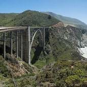
Another shape that performs similarly to the triangles of the truss is the arch. The arch is a commonly used bridge design shape since it also enables loads to be dissipated throughout a wider area. See an example arch bridge in Figure 2: splits (transfers) and continues along the two curving halves of the arch, towards the ground, transferring to the two foundation side supports in the ground to each side of the arch, illustrating the path of load distribution along the arch.")
Another commonly used bridge design element in is the use of girders to provide horizontal support to the flat top surface called the deck. Girders tend to be designed as either an open box-shape or an I-beam shape. These shapes require less beam building material than solid beams while still being able to withstand the compressive and tensile forces being applied. They are also very successful in resisting the torsional forces that bridges experience.
Timing Note
Plan on about six hours of total class time (360 minutes) to conduct the activity. This breaks down into about two hours of instruction and assessment, three hours of building and testing, and one hour for post-activity assessment. The bridge drying time is not included in this time estimate; putting the bridge together takes several class periods, while waiting for the glue to dry.
Before the Activity
- Gather materials and make copies of the Pre-Activity Quiz, Mission Possible Activity Worksheet and Post-Activity Quiz.
- The main test for the activity is to see how much weight each team's bridge prototype can withstand before breaking. To do this, attach a cord around the bridge to enable weights to be added. For example, suspend hooked masses (like those used in science labs) beneath the bridge or hang a small bucket to fill with sand, rocks or other known weight amounts. Add mass incrementally, keeping track of the total weight until the bridge collapses and recording the final breaking weight for use in calculating the strength-to-weight ratio. Alternatively, if you have access to bridge-breaker equipment, use that to test bridge strength. If using this testing method, adjust (as necessary) the bridge size constraint to ensure correct placement of the bridge prototypes in the testing equipment.
- If desired, prepare for the activity introduction by printing out the Broken Bridge Photos Visual Aid (four bridge photos) and slipping them into a manila envelope. Alternatively, search online to find an assortment of broken and collapsed bridge photos to show the class.
With the Students
Administer the pre-activity quiz as described in the Assessment section.
Present the Introduction/Motivation content to the students. Divide the class into teams of three students each. Then proceed with the activity, following the steps of the engineering design process.
Ask: Identify the needs and constraints (10 minutes). Constraints are what engineers call all the requirements and limitations imposed on the design project.
- Show students several images of different bridges and draw their attention to how they are supported, for example, the Golden Gate Bridge shown in Figure 3. While looking at various examples of bridge types and styles, point out the common use of triangles and arches. These shapes are very stable, which is a desirable attribute for bridges.
- The main area of interest for our purposes is the support structure for the roadway (the bridge deck).
- Ask students to identify the main basic shape they see along the side of the bridge deck (in Figure 3). (Answer: Expect students to say triangles.) The triangles provide a strong structural support to evenly distribute the load that bridges experience. That support is the main focus for our tongue depressor bridges.

Figure 3. A truss structure supports the roadway deck of the Golden Gate Bridge in San Francisco CA. - For the design challenge, the following size restrictions apply to your designs. The overall dimensions must be within these parameters (write them on the classroom board):
Length range: 35-43 cm (14-17 inches)
Width range: 10-15 cm (4-6 inches)
Maximum depth: 10 cm (4 inches)
Teacher note: This size limitation permits the opportunity for creativity designs while still keeping the number of tongue depressors to a manageable amount, usually ~100 per bridge.
- Another restriction is that the top of your bridge must be a flat roadway across its full width and length. No structure may extend above the roadway. You may include a ramp at each bridge end. Teacher note: This simplifies the overall design so the main focus is on the bridge support structure. This also gives some flexibility to accommodate whatever bridge testing method is used.
- The permitted materials are wooden tongue depressor sticks and white glue. The sticks may be cut to any length and arranged any way that your team agrees will contribute to the overall purpose to build a strong bridge. No coating of any type is permitted on the sticks.
- The overall goal of the project is to design and build a bridge that has the highest strength-to-weight ratio.
Research the problem (20 minutes)
- Direct teams to research online to examine real-life bridge examples for ideas. Alternatively, do this as a class to speed up this step.
- Keeping in mind the materials that are being used, direct the groups to each list two possible limitations they may face in their designs. For example, arches, I-beams and cables may be difficult to replicate with the given materials (flat wooden sticks).
- Sketch Figure 4 on the classroom board as you explain the tensile (pulling) and compressive (pushing) forces that are acting on the flat bridge. As a quick demonstration, bend one tongue depressor until it starts to break to show how the material is being pulled apart and fails at that point where the load is applied.

Figure 4. Compressive and tensile forces on a beam when a load is applied.
Imagine: Develop possible solutions (20 minutes)
- Have each team member brainstorm and sketch a possible bridge design, transforming their ideas into possible practical solutions.
- Label the bridge sketches with estimated dimensions.
- For each sketch, also estimate how many tongue depressors are needed for that design. Some completed examples of student-created bridge designs are shown in Figures 5 and 6.
Plan: Select a promising solution (10 minutes)
Have teams each confer to discuss, compare and decide upon their preferred design. The most promising solution is the design that they think will be the strongest bridge while using the fewest sticks. This is an important design aspect since the objective is a bridge that can withstand the most weight while being the lightest—maximizing its strength-to-weight ratio.

Create: Build a prototype (40 minutes)
- Bridge construction takes several class periods, while waiting for the glue to dry.
- To minimize warping as they dry, use the binder clips to firmly clamp together the bridge components.
- Once bridges are completed, have teams re-sketch, measure and label their final prototypes since they may have made changes during the build phase.
Test and evaluate prototype (30 minutes for testing; 20 minutes for the worksheet)
- This is the fun testing period! Hand out the worksheets and have students fill in the table to keep track of the measurements and testing results for each bridge.
- Before breaking, measure and record the bridge mass (in grams).
- Place the bridge prototype into the weight-loading setup—such as resting each bridge end on the edges of two tables placed a foot apart. Consistently position each bridge in exactly the same setup.
- Slowly add more weight until the bridge fails. Record the weight at which the bridge breaks, then, if necessary, convert the units from pounds to grams (1 pound = 454 grams).
- Teacher note: Work through the first bridge calculations as a class so students learn how to do them. Calculate the strength-to-weight ratio by dividing the breaking load measured in grams by the mass of the bridge also in grams. This ratio serves as one way to measure bridge performance; a high strength-to-weight ratio is preferred since it means the bridge can support a heavy load, but is itself composed of as little material as possible, which reduces the cost of materials and saves money.
- Have students calculate their teams' strength-to-weight ratio, recording it on the worksheet table and sharing it with the rest of the class.
- Have students analyze the test results, comparing all the design solutions and ranking all the strength-to-weight ratios in order of best performance.
- Ask teams with the top three bridges to informally present their bridge designs to the rest of the class, explaining their design approach.
Improve: Redesign as needed (50 minutes, as part of the post-activity quiz)
Administer the post-activity quiz, as described in the Assessment section. This requires groups to discuss and determine the main cause of failure of their bridge designs, as well as come up with three possible improvement ideas and revised design sketches.
Vocabulary/Definitions
compression: The squeezing or pushing (force) on a material, which tends to make it shorter.
dead load: The weight of a structure by itself when fully constructed.
ratio: A comparison of the size of one number to the size of another number.
shear: The sliding of material that causes layers to move in opposite directions.
tension: The stretching or pulling (force) on a material, which tends to make it longer.
truss: A structural frame based on the rigidity of the triangle shape and composed of straight members. Functions as a beam to support structures such as bridges and roofs.
Assessment
Pre-Activity Assessment
Pre-Quiz: Administer the Pre-Activity Quiz, which asks students to explain the strength of basic geometric shapes and perform some strength-to-weight ratio calculations. Review their answers to gauge their base level of understanding of these concepts. As necessary review the concept and calculation of ratios.
Activity Embedded Assessment
Worksheet: During the testing stage of the engineering design process, have students complete the Mission Possible Activity Worksheet. Doing this keeps all students engaged in the activity as they record the bridge measurements and corresponding breaking loads for all team bridges. Then they convert the breaking load units (if necessary) before calculating their teams' strength-to-weight ratios. They conclude by ranking all bridge prototypes by their ratios, making a comparison of all design solutions. Have the top three teams informally present their bridge designs to the class. Review students' worksheet tables and calculations to gauge their mastery of the concepts.
Post-Activity Assessment
Post-Quiz: Administer the Post-Activity Quiz, which asks students to explain the strength of basic geometric shapes, perform calculations related to strength-to-weight ratios, reflect on their use of the steps of the engineering design process, explain of the main cause of their bridge failures, and describe future bridge design improvement ideas, including a new sketch. Question 1 is the same as the pre-quiz. Review their answers to gauge their post-activity depth of comprehension of the activity concepts.
Safety Issues
Keep students at a fair distance when breaking the bridges to avoid flying parts. Require safety glasses for those applying the test weights or operating the bridge breaker equipment.
Activity Scaling
For lower grades, have students use Popsicle sticks to build the two shapes shown in pre-quiz question 1 to help them visualize what would happen with the application of force on those shapes.
Additional Multimedia Support
Show students an example bridge with a truss support system under the roadway deck, such as the Golden Gate Bridge at: https://commons.wikimedia.org/wiki/File:GoldenGateBridge-001.jpg
Subscribe
Get the inside scoop on all things Teach Engineering such as new site features, curriculum updates, video releases, and more by signing up for our newsletter!More Curriculum Like This

Learn the basics of the analysis of forces engineers perform at the truss joints to calculate the strength of a truss bridge known as the “method of joints.” Find the tensions and compressions to solve systems of linear equations where the size depends on the number of elements and nodes in the trus...
Students are presented with a brief history of bridges as they learn about the three main bridge types: beam, arch and suspension. They are introduced to two natural forces — tension and compression — common to all bridges and structures.

Students learn about the types of possible loads, how to calculate ultimate load combinations, and investigate the different sizes for the beams (girders) and columns (piers) of simple bridge design. Additionally, they learn the steps that engineers use to design bridges.

Copyright
© 2015 by Regents of the University of Colorado; original © 2015 University of California DavisContributors
Nadia RichardsSupporting Program
RESOURCE GK-12 Program, College of Engineering, University of California DavisAcknowledgements
The contents of this digital library curriculum were developed by the Renewable Energy Systems Opportunity for Unified Research Collaboration and Education (RESOURCE) project in the College of Engineering under National Science Foundation GK-12 grant no. DGE 0948021. However, these contents do not necessarily represent the policies of the National Science Foundation, and you should not assume endorsement by the federal government.
Last modified: October 21, 2020
User Comments & Tips