
Quick Look
Grade Level: 8 (6-8)
Time Required: 45 minutes
Expendable Cost/Group: US $2.00
Group Size: 2
Activity Dependency: None
Subject Areas: Physical Science
NGSS Performance Expectations:

| MS-ETS1-2 |
Quick Look

- Grade Level:
- 8 (6 – 8)
- Time Required:
- 45 minutes
- Group Size:
- 2
- Subject Areas:
-
Physical Science -
NGSS Performance Expectations:
MS-ETS1-2
Summary
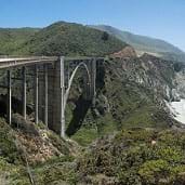
Students explore how tension and compression forces act on three different bridge types. Using sponges, cardboard and string, they create models of beam, arch and suspension bridges and apply forces to understand how they disperse or transfer these loads. Photo of the Golden Gate Bridge (bottom) Photo shows two pieces of string tied to the arms and elbows of a person and stretched over the top of their head forming two A shapes.")
Engineering Connection
Using the countless design possibilities of beam, truss, arch and suspension bridges, civil and structural engineers create the bridges that are essential to the infrastructure of our world. To design bridges of any type, engineers must understand the forces that act on every bridge: compression and tension, and then design bridges to handle these forces without breaking or failing. Teams of engineers decide on the bridge type, design and materials to best distribute the load across an obstacle, and draw detailed design plans, specifying materials, measurements, shapes and angles for construction of the bridge.
Learning Objectives
After this activity, students should be able to:
- Define three major types of bridges, including a beam or truss bridge, an arch bridge, and a suspension bridge.
- Describe and locate compressive and tensile forces acting on various types of bridges.
- Explain situations for which different types of bridges would be best suited.
Educational Standards
Each Teach Engineering lesson or activity is correlated to one or more K-12 science,
technology, engineering or math (STEM) educational standards.
All 100,000+ K-12 STEM standards covered in Teach Engineering are collected, maintained and packaged by the Achievement Standards Network (ASN),
a project of D2L (www.achievementstandards.org).
In the ASN, standards are hierarchically structured: first by source; e.g., by state; within source by type; e.g., science or mathematics;
within type by subtype, then by grade, etc.
Each Teach Engineering lesson or activity is correlated to one or more K-12 science, technology, engineering or math (STEM) educational standards.
All 100,000+ K-12 STEM standards covered in Teach Engineering are collected, maintained and packaged by the Achievement Standards Network (ASN), a project of D2L (www.achievementstandards.org).
In the ASN, standards are hierarchically structured: first by source; e.g., by state; within source by type; e.g., science or mathematics; within type by subtype, then by grade, etc.
NGSS: Next Generation Science Standards - Science
| NGSS Performance Expectation | ||
|---|---|---|
|
MS-ETS1-2. Evaluate competing design solutions using a systematic process to determine how well they meet the criteria and constraints of the problem. (Grades 6 - 8) Do you agree with this alignment? |
||
| Click to view other curriculum aligned to this Performance Expectation | ||
| This activity focuses on the following Three Dimensional Learning aspects of NGSS: | ||
| Science & Engineering Practices | Disciplinary Core Ideas | Crosscutting Concepts |
| Evaluate competing design solutions based on jointly developed and agreed-upon design criteria. Alignment agreement: | There are systematic processes for evaluating solutions with respect to how well they meet the criteria and constraints of a problem. Alignment agreement: | |
International Technology and Engineering Educators Association - Technology
-
The selection of designs for structures is based on factors such as building laws and codes, style, convenience, cost, climate, and function.
(Grades
6 -
8)
More Details
Do you agree with this alignment?
-
Structures rest on a foundation.
(Grades
6 -
8)
More Details
Do you agree with this alignment?
State Standards
Colorado - Science
-
Predict and evaluate the movement of an object by examining the forces applied to it
(Grade
8)
More Details
Do you agree with this alignment?
Materials List
Each group needs:
- Bridge Notes Worksheet, one per student
- 1 small sponge (or flat eraser)
- 1 dark ink pen or marker
- 1 strip of cardboard or poster board (1-in wide x 11-in long; 2.5-cm wide x 28-cm long)
- 1 10-foot (3-m) piece of string or small diameter rope
- 1 11-foot (3- or 4-m) piece of rope
- several textbooks (at least four)
- Bridge Types & Forces Worksheet, one per student
Worksheets and Attachments
Visit [www.teachengineering.org/activities/view/cub_brid_lesson01_activity1] to print or download.Introduction/Motivation
(Optional: Provide each student with a copy of the Bridge Notes Worksheet to fill-in what they know about bridges before the activity and take notes on during the introduction portion of the activity.)
What impacts do bridges have on our communities and cities? Bridges provide essential links between places, providing us with access to resources, other places and other people. Bridges enable roadways to pass through varying terrain, over waterways and through mountains with minimal deviation, saving time in transport or commute or even connecting areas that would otherwise be inaccessible. Who designs these bridges? Civil engineers do. Think about bridges as a way that engineers help us bring worlds together. (Show a map of Vancouver, BC, Canada, or another city with many bridges.) For example, the jutting features of Vancouver would be difficult to access if it were not for the bridges that tie this region together.
Three basic types of bridges used in transportation are: beam and truss bridges, arch bridges and suspension bridges. To understand how bridges work, we must understand the forces that act on every bridge. Two major forces act on a bridge at any given time: compression and tension. Compression, or compressive force, is a force that acts to compress or shorten the thing it is acting on. Tension, or tensile force, is a force that acts to expand or lengthen the thing it is acting on. As a simple example, think of a spring. If we push both ends of the spring towards each other, we are compressing the spring. Thus, a force of compression is acting on it to shorten the spring. If we pull both ends of the spring away from each other, we are stretching the spring. Thus, a force of tension is acting on it to lengthen the spring. It is the purpose of the bridge design to handle these forces without breaking or failing in some manner.
Beam and Truss Bridges

Beam bridges are the simplest and least expensive type of bridge to build. The most simple beam bridges consist of a horizontal beam that is supported on each end by columns or piers. The weight of the beam and any additional load on the bridge is transferred directly to the piers. However, the beam itself must be able to support its own weight and loads between the piers. When a load pushes down on the beam, the top portion of the beam is pushed together by a compressive force while a tensile force stretches the lower portion. The farther apart the supports or piers, the weaker a beam bridge becomes. For larger beam bridges designed for heavy car and railroad traffic, the beams are substituted by simple trusses, or triangular units, which are more economical than solid beams. Engineers have used many different truss patterns in bridges. Therefore, most beam bridges rarely span more than 200 feet (61m), however, old truss bridges crossing major rivers are often as long as 500-600 feet (152-183m), not including end supports such as piers.
Arch Bridges
Arch bridges are the easiest type of bridge to recognize. They are one of the oldest types of bridges and have extraordinary natural strength. Instead of pushing straight down as beam bridges do, the weight of the arch bridge and any additional load on the bridge is carried outward along the curve of the arch to the supports at each end. These supports are called abutments. Abutments distribute the load from the bridge and keep the ends of the bridge from spreading out. The Romans were masters of the arch bridge. Many of their arch bridges used little or no mortar, or "glue," to hold the stones together. The goal of an arch bridge is to carry all loads in compression, without any tensile loads present. The stones in the structures stay together by the sheer force of their own weight and the compression transferred between them. The size of the arch, or the amount of curvature, has a major effect on the effectiveness of this type of bridge. Sometimes, in very large arch bridges, the arch is often reduced in size or flattened down, which results in significant tensile forces that must be factored into the design. Most modern arch bridges span between 100-1,500 feet (30-457m).
Suspension Bridges
Two categories of suspension bridges are: modern suspension bridges and cable-stayed bridges. Modern suspension bridges are characterized by an M-shaped cable pattern. Cables are strung over two towers and then anchored on both ends. The roadway is suspended from the cables by thinner cables or rods. The roadway's weight and any additional load are transferred to the cables, creating a tension force in the cables. The cables then transfer their force to the towers and anchors. Typical modern suspension bridges span distances from 2,000 to 7,000 feet (610-2,134m). Cable-stayed bridges are characterized by an A-shaped cable pattern. Cables are anchored directly to the towers and eliminate the need for an anchorage system. The same tensile and compressive forces are seen in a cable-stayed bridge as they are in a modern suspension bridge. Typical cable-stayed bridges span distances from 500 to 3,000 feet (152-914m), fast becoming the bridge of choice for medium length spans. Cable-stayed bridges also look cool!
Today, we are going to create simple models of each type of bridge that we just discussed to help us learn more about how the forces of tension and compression act on each one. We are also going to think about the situations when an engineer might decide to use each type of bridge when designing roadways.
Procedure
Before the Activity
Prepare the following materials for each group:
- For the beam bridge model, use a pen or marker to draw equally-distant parallel lines along the width (not the length) of the sponge (or eraser) (see Figure 1). If using a sponge, dampen it a bit so it is able to flex.
- For the arch bridge model, cut cardboard into strips.
- For the suspension bridge model, cut the string (or small-diameter rope) into three 2-foot (.6-m) lengths and one 4-foot (1.2-m) piece.
- For the cable-stayed bridge model, cut the larger-diameter rope into one piece 5-feet long and another piece 6-feet long.
- Make copies of the Bridge Types & Forces Worksheet, one per student.
- Divide the class into groups of two students each.
With the Students
- Present to students the basic concepts of each bridge: beam, arch and both suspension bridges as described in the introduction section. Discuss the forces present in each bridge—compression and tension—and the differences in each. Hand out the worksheets for students to complete independently. After students have finished, review their answers to assure their understanding of the behavior of compressive and tensile forces in the different bridge types.
- Have each team make a simple beam bridge (see Figure 1). Position two stacks of textbooks of approximately equal height (3-4 inches or 8-10 cm) so that the flat sponge (or eraser) can "span" them (make distance between the stacks about 1-2 inches or 2-5 cm). Rest the sponge on the two textbook stacks spanning the distance between them. Using a pen or pencil, place a downward force on the top of the sponge—just enough to cause the sponge to bend but not completely collapse.
- What happens to the parallel lines drawn on the top and bottom? (Answer: The lines on the top move closer together. The lines on the bottom move farther apart.)
- Where are the compressive forces located? (Answer: The compressive forces are located on the top.)
- Where are the tensile forces located? (Answer: The tensile forces are located on the bottom.)

- Have each group make a simple arch bridge. Direct them to gently bend their cardboard strips so that they have a curved shape. Then, place the cardboard strip on a smooth flat surface (desktop or tile floor; not carpet) so that it resembles an arch. Using a pen or pencil, place a downward force on the top of the center of the arch. What happens to the arch? (Answer: Expect the arch to collapse because its ends move outward.) Next, place two stacks of textbooks ~5-6 inches (13-15 cm) apart. Place the cardboard strip in-between the two stacks with the curved shape resembling an arch bridge. Press down on the center of the arch (see Figure 2).
- Now what happens? (Answer: The arch should not collapse as easily.)
- What kind of force do the abutments (as represented by the textbooks) impose on the arch, pushing (compression) or pulling (tension)? (Answer: The abutments push back on the arch since the arch is pushing on the abutments.)
- Point out how the stacks of books act as abutments keeping the ends of the arch from spreading apart.

- Have each group make a simple suspension bridge. First, tie one of the 2-foot (.6-m) long pieces of string (or small-diameter rope) around the middle of one ~1-inch (2.5-cm) thick textbook while it is laying flat on the table. Repeat this step with a second 2-foot long piece around a different textbook. Stand these two textbooks on end with the string at the top. Take the third piece of 2-foot string and tie each end to the string on the tops of the textbooks. Position the textbooks about 18 inches (.5 m) apart. Now, push down on the string that connects the two textbooks together (see Figure 3). What happens? (Answer: Notice how the books fall inward relatively easily.)

- Next, remove the strings from the two textbooks. Take the 4-foot (1.2-m) long piece and place a stack of textbooks on top of one end. Place another stack of textbooks on the other end. Using the same 1-inch (2.5-cm) thick textbooks as before, place them under the string standing on end. Try to position the distance between the two textbooks the same as before, 18 inches (.5m). Now, push down on the string between the two textbooks (see Figure 4).
- What happens? (Answer: Expect the books to not fall as easily, even with increasing load.)
- Is the string (cable) in tension or compression? (Answer: The string is in tension; it can only support a tensile force.)
- Are the books (towers) in tension or compression? (Answer: The books are in compression.)
- Do the stacks of books (anchors) push or pull on the string (cable)? (Answer: The stacks of books pull on the string because the string is pulling on them.)
- Point out how the anchorages (textbook stacks) help to stabilize the bridge.
. A view from above of the same setup shows a hand pressing down on the middle of the string across the gap between the two books, which does not result in the books falling inwards.")
- Have each group make a simple cable-stayed bridge. Have students stand up and hold their arms out horizontally to each side. Have them imagine their arms form a bridge and their head is a tower in the middle. In this position, their muscles are holding up their arms. Now, using the rope, have the students become cable-stayed bridges (see Figure 5). Tie each end of the 5-foot (1.5-m) piece of rope around each elbow. Position the middles of the ropes on the tops of their heads. The rope acts as a cable-stay and holds up the elbows. Using the 6-foot (1.8-m) piece, repeat this process tying the ends around their wrists.
- Where do you feel a pushing or compression force? (Answer: The ropes are in tension due to the arm weight (the bridge) while their heads are in compression.)
- Notice how the load (arm weight) is transferred to the tower (heads).
- Step back and notice the pattern made by the strings going over their heads.

- Conclude the activity with one of the post-activity assessment activities described in the Assessment section. For example, have each team pick one type of bridge to design. Using their notes and activity worksheets, have them create a drawing of the bridge in an appropriate location. For example, a modern suspension bridge might cross a body of water that is 3,000 ft (914 m) in length.
Vocabulary/Definitions
abutment: A mass, as of masonry, receiving the arch, beam, truss, etc., at each end of a bridge.
anchor: Any device for securing a suspension bridge at either end.
arch bridge: A bridge that forms the shape of an arch.
beam: A long, rigid, horizontal support member of a structure.
beam bridge: A bridge that consists of beams supported by columns (piers, towers).
cable: A very strong rope made of strands of metal wire, as used to support cable cars or suspension bridges.
cable-stayed bridge: A bridge that consists of one or more towers (or columns) with cables supporting the bridge deck. Characterized by A-shaped cable patterns.
compression: A pushing force that tends to shorten objects.
deck: The "top" of the bridge on which we drive or walk.
engineer: A person who applies their understanding of science and math to creating things for the benefit of humanity and our world.
suspension bridge: A bridge in which the deck is hung from cables.
tension: A pulling or stretching force that tends to lengthen objects.
Assessment
Pre-Activity Assessment
Worksheet: Have students individually complete the pre-activity Bridge Notes Worksheet, and add to it during the Introduction/Motivation portion of the activity. Review their answers to gauge their mastery of the concepts.
Activity Embedded Assessment
Question/Answer: Ask students the questions provided throughout the Procedure section and discuss as a class.
Worksheet: Have students individually complete the Bridge Types & Forces Worksheet. Review their answers to gauge their mastery of the concepts.
Post-Activity Assessment
Design Your Own: After the activity, describe for students how when a community needs a new bridge, teams of engineers decide on the bridge type, design and materials to best distribute the load across an obstacle, and then draw detailed design plans that are used for construction of the bridge. Assign student teams to each choose a bridge type and draw their own detailed design of the bridge, specifying materials, measurements, shapes and angles, just like engineers.
Engineering Scenarios: Engineers use their knowledge of bridge types to select the most appropriate design for a new area. Have students discuss in pairs and share with the class which bridge types they would choose for transportation through the following scenarios:
- A river that is 300 feet (91 m) wide. (Answer: A truss or arch bridge.)
- A ravine that is 1,000 feet (305 m) across. (Answer: A cable-stayed or arch bridge.)
- A body of water that is 10,000 feet (3,048 m) across. (Answer: A suspension bridge.)
- A small patch of swampy land. (Answer: A truss or arch bridge.)
- A waterway in which tall ships must pass through. (Answer: A suspension bridge.)
Safety Issues
- When students are creating their human cable-stay bridges, advise them not to tie the strings so tight that they cut off their circulation.
Activity Extensions
Have students cut out pictures from magazines of the three different bridge types and draw arrows showing where the tensile and compressive forces are acting.
Activity Scaling
- For lower grades, complete the worksheets together, as a class.
- For upper grades, in addition to completing the worksheets individually have each student perform the following: 1) find a bridge near their home, 2) create an image of it by either using a digital camera or making a detailed drawing, and 3) prepare a presentation for the class identifying the following features: bridge type, bridge location, primary uses, and obvious portions of the bridge under tension and compression forces.
Subscribe
Get the inside scoop on all things Teach Engineering such as new site features, curriculum updates, video releases, and more by signing up for our newsletter!More Curriculum Like This

Students are presented with a brief history of bridges as they learn about the three main bridge types: beam, arch and suspension. They are introduced to two natural forces — tension and compression — common to all bridges and structures.

Students learn about the types of possible loads, how to calculate ultimate load combinations, and investigate the different sizes for the beams (girders) and columns (piers) of simple bridge design. Additionally, they learn the steps that engineers use to design bridges.

Working as engineering teams, students design and create model beam bridges using plastic drinking straws and tape as their construction materials. Their goal is to build the strongest bridge with a truss pattern of their own design, while meeting the design criteria and constraints.

Learn the basics of the analysis of forces engineers perform at the truss joints to calculate the strength of a truss bridge known as the “method of joints.” Find the tensions and compressions to solve systems of linear equations where the size depends on the number of elements and nodes in the trus...
References
Dictionary.com. Lexico Publishing Group, LLC. Accessed March 21, 2007. (Source of some vocabulary definitions, with some adaptation) http://www.dictionary.com
Super Bridge: Build a Bridge. Updated October 2000. NOVA Online. Accessed March 14, 2007. (Activity adapted from this resource) http://www.pbs.org/wgbh/nova/bridge/build.html
Copyright
© 2006 by Regents of the University of Colorado.Contributors
Jonathan S. Goode; Joe Friedrichsen; Natalie Mach; Chris Valenti; Denali Lander; Denise W. Carlson; Malinda Schaefer ZarskeSupporting Program
Integrated Teaching and Learning Program, College of Engineering, University of Colorado BoulderLast modified: August 24, 2025
User Comments & Tips