Quick Look
Grade Level: 4 (3-5)
Time Required: 45 minutes
Expendable Cost/Group: US $4.00
Group Size: 4
Activity Dependency: None
Subject Areas: Algebra, Physical Science
NGSS Performance Expectations:

| 4-PS3-2 |
Summary
Using the science and engineering practice of making observations, we can explore the phenomenon of energy transfer. Every day, we are surrounded by circuits that use “in parallel” and “in series” circuitry. Complicated circuits designed by engineers are composed of many simpler parallel and series circuits, but both kinds of circuits transfer energy. During this activity, students make sense of the phenomenon of energy transfer as they build a simple series circuit and discover the properties associated with series circuits. Through this, students engage with the disciplinary core idea that energy can be transferred from place to place by electric currents.
Engineering Connection
Electrical engineers are well versed in the logic of parallel and series circuitry. They design complicated circuits that are composed of many simpler circuits as well as special parts that make sure the use of electricity is safe. For example, electrical and mechanical engineers design circuit breakers that are connected "in series" in the wiring of your house. This "switch" automatically breaks the flow of electricity if it rises above a safe level, preventing an electrical overload from damaging your appliances or causing a fire.
Learning Objectives
After this activity, students should be able to:
- Define, recognize and assemble series circuits
- Explain the path of electrical charge through their circuit
- Apply appropriate computational techniques to solve a variety of problems on series circuit
- Understand that engineers apply their understanding of circuitry to the design of practical, everyday products
Educational Standards
Each TeachEngineering lesson or activity is correlated to one or more K-12 science,
technology, engineering or math (STEM) educational standards.
All 100,000+ K-12 STEM standards covered in TeachEngineering are collected, maintained and packaged by the Achievement Standards Network (ASN),
a project of D2L (www.achievementstandards.org).
In the ASN, standards are hierarchically structured: first by source; e.g., by state; within source by type; e.g., science or mathematics;
within type by subtype, then by grade, etc.
Each TeachEngineering lesson or activity is correlated to one or more K-12 science, technology, engineering or math (STEM) educational standards.
All 100,000+ K-12 STEM standards covered in TeachEngineering are collected, maintained and packaged by the Achievement Standards Network (ASN), a project of D2L (www.achievementstandards.org).
In the ASN, standards are hierarchically structured: first by source; e.g., by state; within source by type; e.g., science or mathematics; within type by subtype, then by grade, etc.
NGSS: Next Generation Science Standards - Science
| NGSS Performance Expectation | ||
|---|---|---|
|
4-PS3-2. Make observations to provide evidence that energy can be transferred from place to place by sound, light, heat, and electric currents. (Grade 4) Do you agree with this alignment? |
||
| Click to view other curriculum aligned to this Performance Expectation | ||
| This activity focuses on the following Three Dimensional Learning aspects of NGSS: | ||
| Science & Engineering Practices | Disciplinary Core Ideas | Crosscutting Concepts |
| Make observations to produce data to serve as the basis for evidence for an explanation of a phenomenon or test a design solution. Alignment agreement: | Energy can be moved from place to place by moving objects or through sound, light, or electric currents. Alignment agreement: Energy is present whenever there are moving objects, sound, light, or heat. When objects collide, energy can be transferred from one object to another, thereby changing their motion. In such collisions, some energy is typically also transferred to the surrounding air; as a result, the air gets heated and sound is produced.Alignment agreement: Light also transfers energy from place to place.Alignment agreement: Energy can also be transferred from place to place by electric currents, which can then be used locally to produce motion, sound, heat, or light. The currents may have been produced to begin with by transforming the energy of motion into electrical energy.Alignment agreement: | Energy can be transferred in various ways and between objects. Alignment agreement: |
Common Core State Standards - Math
-
Add, subtract, multiply, and divide decimals to hundredths, using concrete models or drawings and strategies based on place value, properties of operations, and/or the relationship between addition and subtraction; relate the strategy to a written method and explain the reasoning used.
(Grade
5)
More Details
Do you agree with this alignment?
International Technology and Engineering Educators Association - Technology
-
Tools, machines, products, and systems use energy in order to do work.
(Grades
3 -
5)
More Details
Do you agree with this alignment?
State Standards
Colorado - Math
-
Assess the reasonableness of answers using mental computation and estimation strategies including rounding.
(Grade
4)
More Details
Do you agree with this alignment?
-
Find the unknown in simple equations.
(Grade
4)
More Details
Do you agree with this alignment?
Colorado - Science
-
Show that electricity in circuits requires a complete loop through which current can pass
(Grade
4)
More Details
Do you agree with this alignment?
-
Describe the energy transformation that takes place in electrical circuits where light, heat, sound, and magnetic effects are produced
(Grade
4)
More Details
Do you agree with this alignment?
Materials List
Each group needs:
- 2 D-cell batteries
- 2 wide rubber bands
- 3 #40 light bulbs (available at most hardware stores)
- 3 light bulb holders (available most hardware stores)
- 46 in (50.2 cm) insulated wire (gauge AWG 22) (available at hardware stores)
- 1 basic switch (available at most hardware or electronics stores)
- 4 Series Circuit Building Worksheets
- 4 In a Row Math Worksheets
For the entire class to share:
- wire strippers or sandpaper (to remove insulation at wire ends)
- wire cutters
- small standard screwdriver
- masking tape
Note: Most of the materials required for this lab can be reused in numerous other electricity activities. When the batteries wear out, dispose of them at a hazardous waste disposal site.
Worksheets and Attachments
Visit [www.teachengineering.org/activities/view/cub_electricity_lesson05_activity1] to print or download.Introduction/Motivation
Ask the students in the class if any of them have strings of the small-sized Christmas lights at home? (Many will answer yes.) Ask the students to brainstorm why it is that if one light goes out on a strand of Christmas lights then half of the strand or the entire strand stops working? (Possible answers: The wire is broken, all of the other bulbs are broken, or the circuit is broken.) Many newer strands of lights have more than one wire linking the lights, as a better way to string the lights together; in this case, if one bulb burns out, the rest of the lights do not go out -- only a section goes out.

Ask the students if they ever had a flashlight that required batteries? (Many will answer yes.) Then, inquire how many batteries the flashlight needed (Possible answers: One, two, three or four batteries). Ask the students why larger flashlights require more batteries than smaller flashlights? (Possible answers: Some flashlights need more power, some flashlights need more electricity.) Three AA batteries connected "in series" can provide more voltage than a single AA battery. Explain to the students that the holiday lights and the batteries in a flashlight are similar because both are connected "in series." Electrical circuits as well as batteries can be "in series" or "in parallel." These different circuits are both ways for energy in the batteries to be transferred from the batteries to the lightbulbs, and we can observe that this transfer is taking place when turn on a flashlight or see bright holiday lights at night. During today's activity, we will learn what "in series" means.
Explain to students that electrical and mechanical engineers design circuit breakers to be connected in series with the electrical wiring of your house. The purpose of a circuit breaker is to make sure that too much current does not flow through the electrical wiring in your house and cause equipment failures or a fire. A circuit breaker is similar to a switch; it has an open and closed position. If the electrical current in your house is above a safe level, a circuit breaker opens, creating an open circuit and causing the electricity to shut off.
Procedure
Background Information on Series Circuits
- The current is the same throughout the circuit.
- The total resistance for a series circuit is the sum of the resistances of each element.
- From Ohm's law (I=V/R), we know that the total current is equal to the voltage divided by the total resistance.
- There is a voltage drop across each element in a series circuit that is equal to V=I*R, where V is the voltage of the power source, I is the total current in the circuit, and R is the resistance of the element.
- The sum of the voltage drops across each bulb is equal to the voltage of the power source.
- The total voltage for batteries linked in series is the sum of the voltages of each battery.
- Engineers use switches placed in series to control practically any circuit they make. Just think — most of your electronics have an on/off switch!
Before the Activity
- Assemble all the materials.
- Cut enough wire for each group: two 6 in (7.6 cm) pieces, one 10 in (25 cm) piece, and one 4 in (10 cm) piece.
- You may also want to remove the insulation from the ends of the wires (step 1, below).
With the Students
- Using wire strippers or sandpaper, remove ½ in (1.3 cm) of the insulation from the ends of each piece of wire.
- Using masking tape, connect two batteries in series. The positive terminal of one battery should touch the negative terminal of the second battery.
- Connect the 10 in (25 cm) piece of wire to the positive terminal of one battery using masking tape. The other end of the 10 in wire should be connected to the terminal of one of the light bulb holders. Next, connect a 6 in (7.6 cm) piece of wire to the negative terminal of one of the batteries using masking tape. The other end of the 6 in wire should connect to the switch.
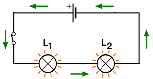
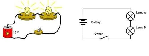
- Put each light bulb in a light bulb holder. Finish constructing the series circuit using the parts you have already made, plus a second light bulb holder, the remaining 6 in (7.6 cm) wire, and the 4 in (10 cm) piece of wire (see Figure 1).

- On your Series Circuit Building Worksheet, draw a circuit diagram of your circuit. Follow along on the worksheet for the rest of the activity.
- Close the switch. What happens to the light bulbs? (Answer: Both bulbs light up.)
- Open the switch. Remove one light bulb from its base. Close the switch. What happens to the light bulb in the circuit? (Answer: The remaining bulb stays off.)
- Open the switch. Replace the light bulb you removed and remove the other light bulb from its base. Close the switch. What happens to the light bulb in the circuit? (Answer: The remaining light bulb does not light up.)
- Open the switch. Make a circuit with three bulbs in series. Close the switch. What happened to the brightness of the bulbs as you increased the number of bulbs in the series circuit? (Answer: The bulbs all got dimmer.)
- Use one team's circuit and observe what happens to the brightness of the bulbs as you add a third battery in series. What happens? (Answer: The bulbs all get brighter.)
- Use the knowledge you have gained about series circuits to complete the In a Row Math Worksheet. Or, if time is limited, assign the worksheet as homework.
Assessment
Pre-Activity Assessment
Prediction: Before conducting the activity, ask students to predict:
- How many batteries do you think it will take to light the two light bulbs?
Activity Embedded Assessment
Worksheet: At the beginning of the activity, hand out the Series Circuit Building Worksheets. Have students follow along, first diagramming the series circuit they have constructed, then filling in answers as they work through the activity; review their answers to gauge their mastery of the subject.
Energy Transfer Discussions: As students work, ask them how energy is being transferred through the circuit as they remove and add light bulbs. Students should observe that the light bulbs in their series circuit only light if all bulbs are connected; they are observing the phenomenon of energy transfer when the circuit is closed, since the chemical energy in the battery needs a path (the circuit) to light the light bulbs.
Post-Activity Assessment
Mental Math Application: Write the equation, I = V ÷ R, on the board. Remind students that this is called Ohm's law. Explain that I = current = flow of electric charge through the circuit (this remains constant through a closed circuit), V = voltage = batteries used, and R = resistance = bulbs used. Challenge the students to explain their team's series circuits in terms of Ohm's law. Have them write the correct letter I, V or R next to the symbols in their circuit drawings. Then, ask the students the following questions:
- What happens to the current (I) when we add another battery (V)? (Answer: The current increases.)
- What happens to the current (I) when we add another light bulb (R)? (Answer: The current decreases.)
- What happens to the current (I) when we have an open switch? (Answer: The current (I) = 0 since no electrons can move through the circuit.)
Series Circuit Advertising: After the activity, ask the student teams what their circuit might be used for? Is it used in a house? Or a toy? Or an appliance? Have the students decide on a name for their circuit and create a magazine ad for their circuit. Suggest they get creative. Have the teams include their circuit diagram and a short explanation of how the circuit works in their ad.
Problem-Solving/Homework: Assess students' understanding of the concepts by assigning the In a Row Math Worksheet as homework.
Safety Issues
- Ask students to be very careful when using the sharp wire strippers and wire cutters.
- Ask students to not play with the insulated wire; they might poke or cut themselves or another student.
Troubleshooting Tips
There must be good electrical contact between all the circuit components. If students have difficulty getting the circuit to work, be sure to double check all the connections.
Do not connect more than four D-cells in series for this activity. Four D-cell batteries connected in series totals 6.0 Volts, and most #40 light bulbs can only sustain 6.3 Volts through the filament.
Activity Extensions
Use a multimeter to measure the voltage across two batteries in series. How does the voltage compare to the voltage of one battery? (Answer: The voltage of two identical batteries in series is twice the voltage of one battery.)
Use a multimeter to determine the voltage across each light bulb and the current in each bulb. Find the resistance of the light bulb using R=V/I. Then, use the multimeter to determine the voltage across two bulbs in series and the current in the bulbs. Find the resistance of this load using R=V/I. Compare the resistance of one bulb to the resistance of two bulbs in series. (Resistances in series add to give the total resistance.) Compare the voltage across one bulb to the voltage across the battery terminals.
Note: A multimeter is an instrument that combines the measuring capabilities of an ammeter (measures current), voltmeter (measures potential difference, or voltage, between two points) and an ohmmeter (measures resistance) in one instrument to take measurements (current, voltage and resistance) from circuits. Multimeters are available at most electronics stores, ranging from about $15-$100.
Activity Scaling
- For younger grades, use the In a Row Math Worksheet as a challenge activity or complete together as a class.
Subscribe
Get the inside scoop on all things Teach Engineering such as new site features, curriculum updates, video releases, and more by signing up for our newsletter!More Curriculum Like This

Students learn that charge movement through a circuit depends on the resistance and arrangement of the circuit components. In one associated hands-on activity, students build and investigate the characteristics of series circuits. In another activity, students design and build flashlights.

In this hands-on activity, students build flashlights and design their own operating series circuit flashlights.

Students explore the composition and practical application of parallel circuitry, compared to series circuitry. Students design and build parallel circuits and investigate their characteristics, and apply Ohm's law.
Copyright
© 2004 by Regents of the University of Colorado.Contributors
Xochitl Zamora Thompson; Sabre Duren; Joe Friedrichsen; Daria Kotys-Schwartz; Malinda Schaefer Zarske; Denise CarlsonSupporting Program
Integrated Teaching and Learning Program, College of Engineering, University of Colorado BoulderAcknowledgements
The contents of this digital library curriculum were developed under a grant from the Fund for the Improvement of Postsecondary Education (FIPSE), U.S. Department of Education and National Science Foundation GK-12 grant no. 0338326. However, these contents do not necessarily represent the policies of the Department of Education or National Science Foundation, and you should not assume endorsement by the federal government.
Last modified: March 17, 2021


User Comments & Tips