Quick Look
Grade Level: 7 (6-8)
Time Required: 6 hours 30 minutes
(3.5 110-minute class periods)
Expendable Cost/Group: US $12.00 This activity also uses some non-expendable (reusable) items such as sensors, multimeters, digital protractors, tape measures, screwdrivers, electric drill and calculators; see the Materials List for details.
Group Size: 3
Activity Dependency: None
Subject Areas: Geometry, Science and Technology
Summary
Students learn about radar imaging and its various military and civilian applications that include recognition and detection of human-made targets, and the monitoring of space, deforestation and oil spills. They learn how the concepts of similarity and scaling are used in radar imaging to create three-dimensional models of various targets. Students apply the critical attributes of similar figures to create scale models of a radar imaging scenario using infrared range sensors (to emulate radar functions) and toy airplanes (to emulate targets). They use technology tools to measure angles and distances, and relate the concept of similar figures to real-world applications.Engineering Connection
Engineers apply their understanding of math and science to the design of radars that transmit radio waves to detect objects, such as aircraft and terrain, by measuring distances between objects and the radar. To continue improving existing radar imaging techniques, engineers have developed radar imaging simulators. A radar imaging simulator uses a three-dimensional model of the target being studied to generate radar images and adjust parameters until the desired image quality is achieved. Similarity and scaling are used to create three-dimensional scale models of targets. In radar imaging, the radar, target and a point of reference on the ground form a right triangle that is used to calculate distances, and detect and identify targets. Attributes of similar figures are used to create scale models of this scenario. Ratios and proportions of corresponding sides are used to test the proportionality of scale models and calculate distances.
Learning Objectives
After this activity, students should be able to:
- Use critical attributes of similar figures to determine if two figures are similar or not.
- Find the measure of an angle in a triangle when given the measure of the other two angles.
- Explain how technology is used to measure angles and distances.
- Relate the hands-on activity to real-world applications in radar imaging.
Educational Standards
Each Teach Engineering lesson or activity is correlated to one or more K-12 science,
technology, engineering or math (STEM) educational standards.
All 100,000+ K-12 STEM standards covered in Teach Engineering are collected, maintained and packaged by the Achievement Standards Network (ASN),
a project of D2L (www.achievementstandards.org).
In the ASN, standards are hierarchically structured: first by source; e.g., by state; within source by type; e.g., science or mathematics;
within type by subtype, then by grade, etc.
Each Teach Engineering lesson or activity is correlated to one or more K-12 science, technology, engineering or math (STEM) educational standards.
All 100,000+ K-12 STEM standards covered in Teach Engineering are collected, maintained and packaged by the Achievement Standards Network (ASN), a project of D2L (www.achievementstandards.org).
In the ASN, standards are hierarchically structured: first by source; e.g., by state; within source by type; e.g., science or mathematics; within type by subtype, then by grade, etc.
Common Core State Standards - Math
-
Decide whether two quantities are in a proportional relationship, e.g., by testing for equivalent ratios in a table or graphing on a coordinate plane and observing whether the graph is a straight line through the origin.
(Grade
7)
More Details
Do you agree with this alignment?
-
Compute unit rates associated with ratios of fractions, including ratios of lengths, areas and other quantities measured in like or different units.
(Grade
7)
More Details
Do you agree with this alignment?
-
Draw (freehand, with ruler and protractor, and with technology) geometric shapes with given conditions. Focus on constructing triangles from three measures of angles or sides, noticing when the conditions determine a unique triangle, more than one triangle, or no triangle.
(Grade
7)
More Details
Do you agree with this alignment?
-
Use facts about supplementary, complementary, vertical, and adjacent angles in a multi-step problem to write and solve simple equations for an unknown angle in a figure.
(Grade
7)
More Details
Do you agree with this alignment?
-
Apply the Pythagorean Theorem to determine unknown side lengths in right triangles in real-world and mathematical problems in two and three dimensions.
(Grade
8)
More Details
Do you agree with this alignment?
International Technology and Engineering Educators Association - Technology
-
Technological systems can be connected to one another.
(Grades
6 -
8)
More Details
Do you agree with this alignment?
-
Differentiate between inputs, processes, outputs, and feedback in technological systems.
(Grades
6 -
8)
More Details
Do you agree with this alignment?
-
Develop innovative products and systems that solve problems and extend capabilities based on individual or collective needs and wants.
(Grades
6 -
8)
More Details
Do you agree with this alignment?
-
Analyze how different technological systems often interact with economic, environmental, and social systems.
(Grades
6 -
8)
More Details
Do you agree with this alignment?
State Standards
Texas - Math
-
represent mathematical and real-world problems involving ratios and rates using scale factors, tables, graphs, and proportions;
(Grade
6)
More Details
Do you agree with this alignment?
-
communicate mathematical ideas, reasoning, and their implications using multiple representations, including symbols, diagrams, graphs, and language as appropriate;
(Grades
6 -
8)
More Details
Do you agree with this alignment?
-
apply and extend previous understandings of operations to solve problems using addition, subtraction, multiplication, and division of rational numbers.
(Grade
7)
More Details
Do you agree with this alignment?
-
write and solve equations using geometry concepts, including the sum of the angles in a triangle, and angle relationships.
(Grade
7)
More Details
Do you agree with this alignment?
-
generalize the critical attributes of similarity, including ratios within and between similar shapes;
(Grade
7)
More Details
Do you agree with this alignment?
-
use trigonometric ratios to calculate distances and angle measures as applied to fields.
(Grades
9 -
12)
More Details
Do you agree with this alignment?
Texas - Science
-
analyze data to formulate reasonable explanations, communicate valid conclusions supported by the data, and predict trends.
(Grades
6 -
8)
More Details
Do you agree with this alignment?
-
identify advantages and limitations of models such as size, scale, properties, and materials; and
(Grades
6 -
8)
More Details
Do you agree with this alignment?
Materials List
Each group needs:
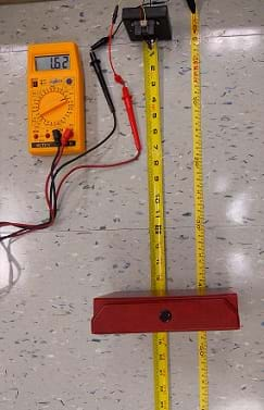
- 1 infrared sensor, specifically, the Sharp GP2Y0A02YK0F IR package for $14.50 at Acroname http://www.acroname.com/robotics/parts/R144-GP2Y0A02YK.html (includes an infrared sensor, JST 3-pin connector and three pre-crimped wires; this infrared sensor takes a continuous distance reading and returns a corresponding analog voltage with a range of 20 to 150 cm [7.87 to 59.05 in])
- 4 AA battery holder with cover and switch, such as item #W32971 for $1.95 at Pitsco http://www.pitsco.com/store/detail.aspx?ID=5163
- 3 AA alkaline batteries, such as item #W51046, two batteries for $2.93 at Pitsco
- 2 plastic wire-connectors, such as item #53213, 25 for $2.69, at Lowes
- 2 4-40 x ¾" Hillman combo round-head standard machine screws with nuts, such as item #62045, 12 for $1.18 at Lowes http://www.lowes.com/pd_62045-37672-491276_0__?productId=3036646
- 2-inches of 18 AWG shield wire, such as item #W12741, a 55-foot spool for $5.95, at Pitsco http://www.pitsco.com/18-Gauge_Stranded_Wire?SKU=W12741&tp=1
- 2 alligator clips, such as item #44564, two-pack for $1.96 at Lowes
- ~3 inches of electrical tape (or, give each team a roll so teams do not have to wait for tape), such as item #19456, 10-roll pack for $4.97 at Lowes
- precision screwdriver set, for assembling the sensor modules, such as item #W944S, a Performance Tool 6-piece screwdriver set for $2.49 from O'Reilly Auto Parts at http://www.oreillyauto.com/site/c/detail/PFM0/W944S/N0762.oap?ck=Search_N0762_PFM_-1_-1&mn=Performance+Tool&mc=PFM&pt=N0762&ppt=C0185
- mini multimeter, such as item #W31912 for $23.95 (includes 9V battery, test leads and probe) at Pitsco http://www.pitsco.com/store/default.aspx?KeyWords=W31912
- digital protractor, such as item #79017 for $24.98 at Lowes http://www.lowes.com/pd_79017-56005-1702_0__?Ntt=79017
- 25-foot metric and SAE tape measure, such as item #317494 for $10.98 at Lowes
- 1 toy airplane, such as a balsa wood glider, item #W50364 with a 12-inch wingspan for $3.95 at Pitsco http://www.pitsco.com/store/detail.aspx?KeyWords=W50364&ID=2706&c=&t=&l
- 3 balloon sticks with cups or 3 wooden craft sticks, to support toy airplane, such as Knextion balloon sticks with (cone-shaped) cups, 12 for $12.59 from Amazon at http://www.amazon.com/MULTICOLOR-BALLOON-STICKS-WITH-DOZEN/dp/B007BDDKJ2/ref=sr_1_4/183-7964811-0362554?ie=UTF8&qid=1381260627&sr=8-4&keywords=balloon+sticks+and+cups
- foam core board, such as 20 x 30-in x 3/16-in thick polystyrene core board, 10-pack for $31.03 at Walmart
- modeling clay (one-pound package), to use as desired, perhaps to secure the stick holding the airplane, such as item #W37660 for $3.50 at Pitsco
- 5 zip ties, such as item #292689, 500-pack of 8-inch nylon cable ties for $14.84 at Lowes
- 4 rubber bands, such as item #W33567, 2300 size #16 rubber bands for $5.95 at Walmart
- 4 3-oz plastic cups, such as 100-pack for $8.16 at Walmart
- gallon-size plastic zip lock bag, to contain materials needed to assemble and calibrate the sensor
- classroom object such as a box, book or the wall, to help in calibrating the sensor by measuring the distance between the sensor and the object
- Assembling the Sensor Handout
- Calibrating the Infrared Range Sensor Worksheet
- The Invisible Radar Triangle Worksheet
- The Invisible Radar Triangle-Scale Model Rubric
- The Invisible Radar Triangle Quiz, one per student
- notebook (or lined paper), for documenting design plans, one per student
- TI-84 graphing calculator
To share with the entire class:
- computer and projector to show a PowerPoint® file, The Invisible Radar Triangle Presentation
- Phillips screwdriver, for assembling the sensor
- electric drill with 9/64 drill bit, for assembling the sensor
- wire strippers, for assembling the sensor
- white glue, for students to use as desired, perhaps to assemble the airplane or glue plastic cups together to look like a radar system
- fishing line, such as a 225-yd roll of 25-lb clear monofilament fishing line for $3.10 by Eagle Claw at http://www.shopping.com/eagle-claw-monofilament/UOyxnMMhSVvCreIwNuuEDQ==/info?sb=1
- clear scotch tape, to tape down the tape measure
Worksheets and Attachments
Visit [www.teachengineering.org/activities/view/utpa_invisible_activity1] to print or download.Pre-Req Knowledge
Prior to this activity, students should know:
- How to write and simplify ratios.
- How to use ratios to describe proportional relationships.
- How to use protractors to measure triangle angles.
- That the sum of the interior angles of a triangle is 180 degrees.
- That similar figures have congruent corresponding angles and proportional corresponding sides.
- That in two similar triangles a proportion can be used to find a missing side.
Introduction/Motivation
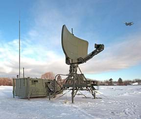
(Open The Invisible Radar Triangle Presentation, a 10-slide PowerPoint® file. Start as a "slide show from the beginning." On slide 1, click on the "Sound Icon" located below the title to play the sound of flying aircraft. As the sound plays, click elsewhere on the same slide to bring in a photograph of a radar system with aircraft flying above it. Use slides 2-6 to introduce students to radar imaging. Students see how electromagnetic waves are sent and reflected back in radar imaging [slide 2] and how an invisible radar triangle is formed [slides 3 and 4]. Use slides 5 and 6 to motivate students by explaining the importance of radar imaging. Present students with the following information as you show the slides.)
(Slide 2) Radar imaging is used to create images of various objects to detect, classify and identify their sizes and directions of movement. For example, to conduct military surveillance, monitor weather and take images of the Earth and other planets. While many different types of radar systems are in use, this activity looks at the inverse synthetic aperture radar (ISAR). ISAR is widely used for military surveillance for its ability to work in all weather conditions.
ISAR is a technique used to create radar images of targets that continually move, such as airplanes, cars and planets. A stationary antenna sends radio waves to a moving target. The radio waves are reflected back to the antenna, stored and processed to form a two-dimensional image (picture) of the target.
(Slide 3) This drawing illustrates a radar imaging scenario. The distance from the radar to the target is the slant range. The horizontal distance from the radar to a point of reference on the ground under the target is the ground range. If the target, radar and point of reference are connected by an imaginary line, they form an invisible right triangle.
(Slide 4) Engineers use this invisible triangle and some equations to calculate the distance, direction and elevation angle of the target.
(Slide 5) ISAR radar imaging is mainly used by government agencies for surveillance, but engineers have designed many radar systems for many different uses. For example, NASA uses radars to study the Earth, other planets and space. Radar systems are also used to monitor weather.
(Slide 6) To continually improve existing radar imaging techniques, engineers have developed radar imaging simulators. A radar imaging simulator uses a three-dimensional model of the target being studied to generate radar images and adjust parameters until the desired image quality is achieved. Similarity and scaling are used to create three-dimensional scale models of targets.
(Slide 7, the activity challenge) Imagine that you are an army soldier who monitors radar at a military base. You are asked to make a presentation to a group of people on how radar imaging is done. Your audience is not familiar with radar imaging. You decide to use a model to help your audience better understand your presentation. Your model must be similar to the one shown in the presentation. How can a model help you present this concept?
In this activity, you are going to play the role of radar engineers. You will learn how the concept of similar figures can help you construct proportional models. Let's plan!
Procedure
Background
Adapt the materials and the procedures described for this activity to meet your needs. Refer to The Invisible Radar Triangle Presentation for background information on radar imaging. If further information is needed about radar imaging, see the Radartutorial.eu website listed in the References section.
During the activity, student teams complete worksheets in which they use scales to create triangle setup models to represent their emulated radar imaging scenarios. In their scale models, teams assemble infrared sensors that emulate the functions of a radar system. They design and create scale models of their scenarios. They use proportions to find a missing side in a pair of similar figures. They use ratios to compare the lengths of the corresponding sides and the measure of the corresponding angles to determine if the model is similar to the original model or not.
At activity end, students demonstrate their knowledge and understanding of similar figures and radar imaging by answering quiz questions.
Before the Activity
- Make copies of Assembling the Sensor Handout, Calibrating the Infrared Range Sensor Worksheet, The Invisible Radar Triangle Worksheet and The Invisible Triangle-Scale Model Rubric, one each per group.
- Make copies of the The Invisible Radar Triangle Quiz, one per student.
- Gather materials and prepare kits, one per group, containing all the materials needed for the activity. In a zip lock bag for each group, put the materials needed to assemble and calibrate the sensor. See the sensor assembly and calibration documents for a list of these items.
- Several days before the activity, study the sensor assembly and calibration documents to become familiar with the materials.
- Generate as many scale factors as groups in your class, so each group can be assigned a different scale. For each group, type the group number on top of a letter-size sheet and the scale factor information to be used by the group to construct its model. For example, Group 1 scale factor: 1 km = 4 cm; Group 2 scale factor: 2 km = 7 cm, etc.
- Reset the TI-84 graphing calculators before the activity, and assign each group a calculator to use during the activity.
- Divide the classroom into work stations so that each group can be assigned its own space.
- Prepare a computer and projector to show the class The Invisible Radar Triangle Presentation, a 10-slide PowerPoint file as part of presenting the Introduction/Motivation section content.
With the Students—Day 1
- Introduce the activity through the PowerPoint presentation and the Introduction/Motivation content, including introducing the engineering activity challenge on slide 7.
- Divide the class intro groups of three students each and assign groups to work stations.
- Show students the slide 8 example in the PowerPoint presentation.
- Show slide 9 and direct students to brainstorm ideas on how they can make models of the radar imaging scenario. Prompt them to determine the measurement of the third angle. Have teams design their models on paper.
- Show students slide 10 to introduce them to the infrared range sensor that they will use to emulate the function of radar in their models.
- Give students the materials needed to construct the sensor module according to the sensor assembly instructions. Assist students, as needed, in following the steps to make sure that their sensor modules are constructed correctly.
- After students have finished constructing their sensor modules, review the sensor calibration instructions and distribute the calibration worksheets.
- Direct student teams to calibrate their sensors and complete the calibration worksheet. Provide classroom objects such as books, boxes and walls for teams to use in the calibration process.
- Direct students to input their data into the TI-84 calculators following the detailed steps on page 2 of the calibration worksheet. This information is used on Day 2 to measure distances.
With the Students—Day 2
- Direct student groups to assemble at their assigned work stations.
- Give each group the materials needed to make their models: their infrared sensor modules, a multimeter, their assigned graphing calculator and The Invisible Radar Triangle Worksheet.
- Assign groups the scale factors that they will use to calculate the dimensions of their models.
- Direct students groups to each come up with a plan to create a model of the radar imaging scenario provided in the worksheet (refer to Figure 1). Direct student groups to use their assigned scale factors to calculate and report the dimensions of the ground range and the airplane's altitude of their models on the worksheet (questions 1 and 2).
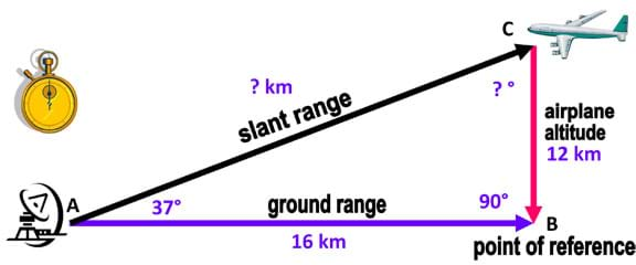
Figure 1. A triangle is formed by connecting lines between the target, radar and point of reference in a radar imaging scenario. - Ask student groups to list in their notebooks the steps and materials to be used to create their models and then present them to the teacher. Hand out the rubric to guide students in their planning. As teams design their models on paper, have them list for the teacher the materials they need to construct their models, such as glue, modeling clay, tape, plastic cups, balloon sticks with cups, foam boards, or other materials available in the classroom. (Students are free to use their creativity in use of the materials. In the past, students have used the balloon sticks/craft sticks and cups/cones to support the toy airplane and hold it in place. They have used the modeling clay to secure the stick or secure the plane to the stick. They have also glued together the plastic cups to imitate radar systems equipment. Solutions will vary by team. See Figure 2 as an example.)
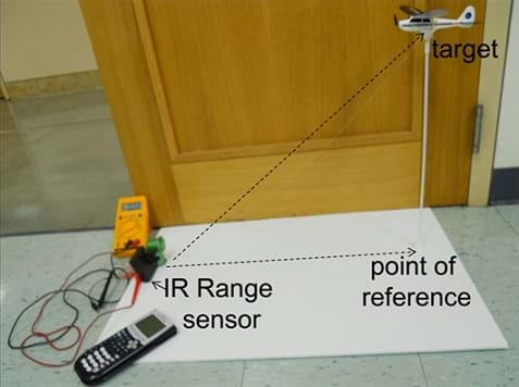
Figure 2. An example student activity setup—a model of a radar imaging scenario using a toy airplane positioned above an infrared range sensor. - Direct student groups to proceed to build their models.
With the Students—Day 3
- After student groups finish building their models (refer to Figure 2 as an example), have them complete the remaining questions on worksheet. Following worksheet instructions, students use their sensors, multimeters and graphing calculators to measure the slant range (distance between the airplane and the radar) in their models.
- Monitor student work and provide feedback and assistance, as needed.
- Have student groups present their models to the rest of the class and justify the answers they documented on their worksheets. Evaluate their understanding of similar figures using the rubric criteria and examining their completed worksheets.
With the Students—Day 4
- Have students complete the quiz as a mini assessment, as described in the Assessment section.
Vocabulary/Definitions
angle: Two rays united at a common end point called a vertex.
congruent angles: Angles that have the same measurement.
ground range: The distance between the radar and a point of reference on the ground in a radar imaging scenario.
inverse synthetic aperture radar : (ISAR) A radar system that utilizes an antenna and the movement of a target (airplane, car, planet, etc.) to generate high-resolution remote sensing imagery.
proportion: A relationship between different things or parts with respect to comparative size, number or degree; relative magnitude or extent; ratio. Specifically in mathematics, a relationship between four numbers or quantities in which the ratio of the first pair equals the ratio of the second pair, such as a/b = c/d.
ratio: A quantitative relationship between two amounts, showing the number of times one value contains or is contained within the other. Examples: the ratio of men's jobs to women's jobs is 8 to 1; the ratio of the lengths of two sides of a triangle is 5 to 2, written 5:2 or 5/2.
scale model: A model that represents an object at a size that is larger or smaller than its real size. A scale factor is used to enlarge or reduce all dimensions proportionally.
similar figures: Figures with the same shape but not necessarily the same size. Their corresponding sides are proportional and their corresponding angles measure the same.
slant range: The distance between the radar and the target in a radar imaging scenario.
target: The object (aircraft, car, planet, etc.) being imaged in a radar imaging scenario.
Assessment
Pre-Activity Assessment
Brainstorming: Prompt students to brainstorm ideas on how they can design models of the triangular scenario in radar imaging. Lead a class brainstorming discussion guided by the following questions:
- How can a model help you present this concept? (Example answers: A model provides an audience with a visual representation of the triangle arrangement of the radar imaging components, helping them to understand what is going on. Models make it easier to understand since they give you concrete and tangible objects to help you visualize something that is otherwise hard to imagine.)
- How can you find the measurement of the third angle in the triangle? (Example answer: You add the measurements of the two given angles and then subtract the sum from 180 since the sum of the three angles in a triangle is 180 degrees.)
- How can you make a realistic model of the scenario? (Example answer: The model must be proportional to the actual triangle formed in a radar imaging scenario.)
- How can the concept of similar figures help you construct a proportional model to make it more realistic? (Example answer: In similar figures, the corresponding sides are proportional and the corresponding angles are congruent [measure the same]. We can use a scale factor to calculate the lengths of the sides of the model triangle. We can also measure the angles in the model to make sure they measure the same as the ones in the actual triangle.)
Activity Embedded Assessment
Sensor Assembly and Calibration: Direct student teams to follow the instructions on the Assembling the Sensor Handout and Calibrating the Infrared Range Sensor Worksheet to assemble and calibrate the sensors. Monitor their progress to ensure sensors are being assembled correctly.
Worksheet: Have each group complete The Invisible Radar Triangle Worksheet to document the dimensions of their scale models. Also have students design their models on paper, listing for the teacher the materials they will need to construct their models, such as glue, modeling clay, tape, plastic cups, balloon sticks with cups/cones, boards. The worksheet helps them compare their model dimensions to the worksheet's pictorial model to determine if their models are proportional or not. They compare the ratios of the corresponding sides in the scale model they built and the pictorial model provided in the radar imaging scenario to determine if they are proportional or not. If the ratios of the corresponding sides are equal and the corresponding angles measure the same, then the built model and the pictorial model are proportional.
Post-Activity Assessment
Group Presentations: Have groups present their models and conclusions to the class. Evaluate each group's model and presentation using The Invisible Radar Triangle Scale Model Rubric, which includes criteria for dimension accuracy, use of sensor, correct use of math terminology and overall neatness/attractiveness. In their conclusions, expect students to be able to use correct mathematical terms to explain whether or not their models are proportional to the pictorial model. For example: "the ratio of the corresponding sides in the model and the picture are equal, and the corresponding angles measure the same. Therefore, we concluded that our model was proportional to the one in the diagram." Also notice whether students correctly apply math concepts and appropriately use math vocabulary as they justify their answers. Expect students to be able to list the following attributes of similar figures in their presentations:
- Similar figures are figures that have the same shape and not necessarily the same size.
- In similar figures, corresponding angles are congruent and corresponding sides are proportional.
Mini-Assessment: At activity end, after the presentations, administer the nine-question The Invisible Radar Triangle Quiz in which students use the attributes of similar figures to determine if two figures are similar (proportional) or not. This demonstrates students' abilities to apply recently acquired knowledge to solve mathematical problem, with additional questions to reinforce the connection of the concept of similar figures to radar imaging systems designed and used by engineers.
Safety Issues
Instruct students about the appropriate use of the tools and equipment
Troubleshooting Tips
Before presenting the activity to the class, go through it as if you were a student, so as to be ready for questions that may come up during the activity.
Organizing group materials in kits in advance saves time during the activity.
Activity Extensions
Through a class discussion, gather data from all groups and complete The Invisible Radar Triangle-Class Data Worksheet.
Have students use critical attributes to determine if the "invisible radar triangles" created in their models are similar and justify their answers. Have students graph the ratios of the corresponding sides to identify proportional relationships.
Activity Scaling
- For lower grades, provide scale drawings and have students find equivalent ratios by comparing corresponding sides.
- For upper grades, conduct the extension activities and have students graph the ratios of the corresponding sides, and describe proportional and non-proportional relationships.
Subscribe
Get the inside scoop on all things Teach Engineering such as new site features, curriculum updates, video releases, and more by signing up for our newsletter!More Curriculum Like This

Students learn the importance of the Pythagorean theorem as applied in radar imaging. They use a sensor unit with IRED (infrared emitting diode) to measure triangle distances and the theorem to calculate and verify distances. Student groups calibrate the sensor units to ensure accurate distance meas...

Students are introduced to the technology of flexible circuits, some applications and the photolithography fabrication process. They are challenged to determine if the fabrication process results in a change in the circuit dimensions since, as circuits get smaller and smaller (nano-circuits), this c...

Students learn about nondestructive testing, the use of the finite element method (systems of equations) and real-world impacts, and then conduct mini-activities to apply Maxwell’s equations, generate currents, create magnetic fields and solve a system of equations. They see the value of NDE and FEM...
References
U.S. Air Force. The official website of the U.S. Air Force. Accessed June 29, 2012. (Source of images used in the activity and PowerPoint presentation) http://www.af.mil/photos/media_search.asp
Wolff, Christian. Radar Basics. Radartutorial.eu. Accessed June 29, 2012. (Resource for additional background information) http://www.radartutorial.eu/index.en.html
Wolff, Christian. Synthetic Aperture Radar. Radartutorial.eu. Accessed June 29, 2012. (Source of background information; photos, interactive diagrams and inspiration for triangle diagram) http://www.radartutorial.eu/20.airborne/ab07.en.html#this
Copyright
© 2013 by Regents of the University of Colorado; original © 2012 The University of Texas-Pan AmericanContributors
Rocio Denise Nava; Mounir Ben GhaliaSupporting Program
RET-ENET Program, Electrical Engineering Department, The University of Texas-Pan AmericanAcknowledgements
This activity was created through The University of Texas-Pan American's Electrical Engineering Research Experiences for Teachers in Emerging and Novel Engineering Technologies (RET-ENET) Program with support from National Science Foundation grant no. CNS 1132609. However, these contents do not necessarily represent the policies of the National Science Foundation, and you should not assume endorsement by the federal government.
Last modified: March 17, 2018


User Comments & Tips