Quick Look
Grade Level: 5 (4-6)
Time Required: 2 hours
(can be divided into two activities)
Expendable Cost/Group: US $0.50 Additional non-expendable (re-usable) items of ~$34 per group are required; see the Materials List for details.
Group Size: 3
Activity Dependency:
Subject Areas: Chemistry, Measurement
NGSS Performance Expectations:

| 5-ESS3-1 |

Summary
Students learn about electricity and air pollution while building devices to measure volatile organic compounds (VOC) by attaching VOC sensors to prototyping boards. In the second part of the activity, students evaluate the impact of various indoor air pollutants using the devices they made.Engineering Connection
Environmental engineers measure air pollution and work with scientists to determine the sources, magnitude, and health effects of various pollutants. Most air quality measurement devices are expensive and/or immobile. Engineers work to create less expensive, smaller and more reliable monitoring devices.
Learning Objectives
After this activity, students should be able to:
- Explain the connections in a prototyping board (breadboard).
- Explain that current travels from the negative terminal to the positive terminal of a breadboard, and that any element hooked up to a breadboard needs to be attached to both terminals.
- Identify several products in their homes and school that emit VOCs.
- Recognize that everyday products emit pollution and can have negative effects on human health.
Educational Standards
Each TeachEngineering lesson or activity is correlated to one or more K-12 science,
technology, engineering or math (STEM) educational standards.
All 100,000+ K-12 STEM standards covered in TeachEngineering are collected, maintained and packaged by the Achievement Standards Network (ASN),
a project of D2L (www.achievementstandards.org).
In the ASN, standards are hierarchically structured: first by source; e.g., by state; within source by type; e.g., science or mathematics;
within type by subtype, then by grade, etc.
Each TeachEngineering lesson or activity is correlated to one or more K-12 science, technology, engineering or math (STEM) educational standards.
All 100,000+ K-12 STEM standards covered in TeachEngineering are collected, maintained and packaged by the Achievement Standards Network (ASN), a project of D2L (www.achievementstandards.org).
In the ASN, standards are hierarchically structured: first by source; e.g., by state; within source by type; e.g., science or mathematics; within type by subtype, then by grade, etc.
NGSS: Next Generation Science Standards - Science
| NGSS Performance Expectation | ||
|---|---|---|
|
5-ESS3-1. Obtain and combine information about ways individual communities use science ideas to protect the Earth's resources and environment. (Grade 5) Do you agree with this alignment? |
||
| Click to view other curriculum aligned to this Performance Expectation | ||
| This activity focuses on the following Three Dimensional Learning aspects of NGSS: | ||
| Science & Engineering Practices | Disciplinary Core Ideas | Crosscutting Concepts |
| Obtain and combine information from books and/or other reliable media to explain phenomena or solutions to a design problem. Alignment agreement: | Human activities in agriculture, industry, and everyday life have had major effects on the land, vegetation, streams, ocean, air, and even outer space. But individuals and communities are doing things to help protect Earth's resources and environments. Alignment agreement: | A system can be described in terms of its components and their interactions. Alignment agreement: Science findings are limited to questions that can be answered with empirical evidence.Alignment agreement: |
Common Core State Standards - Math
-
Perform operations with multi-digit whole numbers and with decimals to hundredths.
(Grade
5)
More Details
Do you agree with this alignment?
-
Solve real-life and mathematical problems using numerical and algebraic expressions and equations.
(Grade
7)
More Details
Do you agree with this alignment?
International Technology and Engineering Educators Association - Technology
-
Illustrate how, when parts of a system are missing, it may not work as planned.
(Grades
3 -
5)
More Details
Do you agree with this alignment?
-
Follow directions to complete a technological task.
(Grades
3 -
5)
More Details
Do you agree with this alignment?
State Standards
Colorado - Science
-
Show that electricity in circuits requires a complete loop through which current can pass
(Grade
4)
More Details
Do you agree with this alignment?
Materials List
Each group needs:
- breadboard ($3.50, available in electronic stores or online, for example http://www.pololu.com/catalog/product/351)
- battery holder ($1.50, available in electronic stores or online, for example http://www.pololu.com/catalog/product/1159)
- 4 AA batteries
- terminal block ($0.50, available in electronic stores or online, for example http://www.pololu.com/catalog/product/830)
- VOC sensor ($18, for example, sensor model TGS 2620 at http://www.figarosensor.com/)
- multimeter (~$10)
- 1/8 of a kitchen sponge for each VOC source
- Elementary and Middle VOC Worksheet or High School VOC Worksheet, one per student (depending on grade level)
To share with the entire class:
- 1 wire kit ($1.30, available in electronic stores or online, for example http://www.pololu.com/catalog/product/313)
- VOC sources (gather items from the classroom, such as cleaning products, white-out, permanent markers, dry erase markers, non-toxic markers, school glue, non-toxic glue, whiteboard cleaner, and duct tape; ask students to bring in items from home, such as nail polish, nail polish remover, alcohol, scented cosmetics/shampoo, vanilla extract, perfume, spray deodorant, cleaning products such as dish soap, air freshener, paint cans, and moth balls)
- 2-3 buckets (or any containers that can hold about a quart of water)
- 1 light-emitting diode (LED)
Worksheets and Attachments
Visit [www.teachengineering.org/activities/view/cub_air_lesson09_activity3] to print or download.Pre-Req Knowledge
A familiarity with volatile organic compounds (VOCs), and the ability to name several VOC sources. Conduct this activity after the I've Gotta Get Some Air associated lesson.
Introduction/Motivation
Did you know that air pollution is present both indoors and outdoors? We rely on air quality engineers to measure air pollution and work with scientists to determine the sources, magnitude and health effects of various pollutants. These measurements enable agencies, like the Environmental Protection Agency, to regulate emissions and make health recommendations to the public.
Most air pollution measurement devices are expensive and/or immobile. In order for a device to adequately measure human exposure to pollutants, it must be attached to the person sampling at all times. This is because air pollution is caused by many indoor and outdoor sources, and varies from place to place. Engineers work to create less expensive, smaller and more reliable monitoring devices.
Today you will make a device that uses one of the smallest and least expensive volatile organic compound (VOC) sensors available! VOCs are any gases made of carbon (excluding carbon monoxide and carbon dioxide), which participate in atmospheric photochemical reactions. This is a fancy way of saying that they react with sunlight to produce ground-level ozone. Some examples of VOC sources are cleaning products, scented cosmetics, and dry cleaning. VOCs are also bad for human health, and exposure can cause the following symptoms: eye, nose and throat irritation, headaches, loss of coordination, nausea, damage to liver, kidney, and central nervous system, allergic skin reactions, dyspnea, declines in serum cholinesterase levels, fatigue and dizziness. Quite a long list! And, VOCs are usually present in higher concentrations indoors than outdoors (up to 10 times more).
The VOC sensor you will use in this project requires an external power source, which means that we need to find a way to give the unit power. A "breadboard" is a type of prototyping board that makes it easy to connect electrical devices to each other. In order to use a breadboard, you should understand the basics of voltage, current and resistance. Now, let's watch a short video that will explain to us how this works. (Show students the Electricity Video).
Procedure
Background
Students learn about electricity and air pollution while building devices to measure volatile organic compounds (VOCs). Students attach VOC sensors to prototyping boards, and then use their devices to evaluate the impact of various indoor pollutants. Note: A 1 kOHM resistor should be used to connect to the VOC sensor on the breadboard
Before the Activity
- Hook up the VOC sensors to the breadboards (let more advanced students do this step themselves). Figure 1 shows an upside-down sensor. The numbers on each leg indicate the column on the breadboard that leg should be attached to. Move the legs closest to the notch (see arrow) out, so that each leg fits in a different column in the breadboard. Figure 2 shows how the sensor looks on the breadboard.
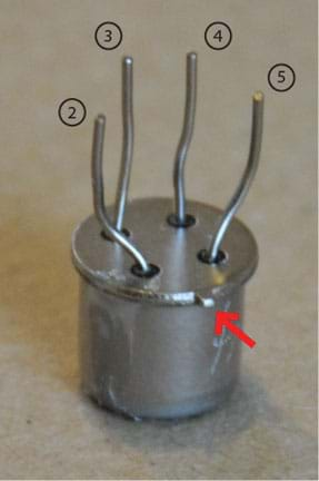
Figure 1: VOC sensor with notch.
Make sure that the notch faces the centerline of the breadboard (the arrow points to the notch). As you can see in Figure 2, the sensor covers columns 2, 3, 4 and 5. Figure 1 shows labels for each of the legs and where they go. Columns 2 and 3 are connected to the positive terminal with yellow wires, column 4 is connected to the negative terminal with a resistor, and column 5 is connected to the negative terminal with the green wire (you can use any color wire).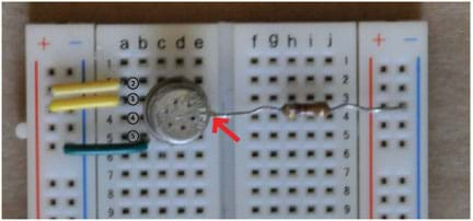
- Place the batteries in the battery packs.
- Consider spending a day talking about air pollution, and completing the associated activity, The Search for Secret Agents, prior to doing this activity. If you do this activity first, you can then test the pollutants you found in your school. If you do not complete The Search for Secret Agents, ask students to instead brainstorm pollutants they think might be found in their school.
- Make copies of the attached Elementary and Middle VOC Worksheet or High School VOC Worksheet, one per student (depending on grade level).
- Prepare to project the attached VOC Sensor Presentation PowerPoint file.
- Ask students to bring in VOC sources from home; see the suggested items in the Materials List.
With the Students
Day 1
- Verbally quiz students about the Electricity Video to make sure they understand the main concepts.
- Introduce students to the concept of a short circuit. Explain that a short circuit occurs when you connect the positive end of a voltage source directly to the negative end, with little or no resistance. This results in excessive current, which causes the circuit to get really hot or explode, destroying the components of the circuit. Never connect a wire to both ends of a voltage source without adding resistance to the circuit!
- Project the first slide of the attached VOC Sensor Presentation. This slide (also shown in Figure 3) displays the breadboard connections. Each breadboard column is connected, with a break in the center, as shown by the green lines. Each row on the top and bottom is connected horizontally, as displayed by the red and black lines.
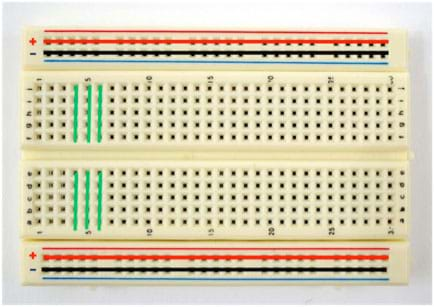
Figure 3: Breadboard with lines indicating connections. - Hand out breadboards and two wires to each group.
- Demonstrate how to connect the two positive lines and two negative lines of the breadboard (see Figure 4), then have the students do the same. Explain that they are doing this because the two sides are not connected, and a power source can only be connected to one side of the breadboard. By connecting the two sides to each other, both sides can be used for power (positive side, red line) and ground (negative side, black line).
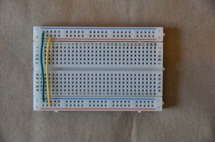
Figure 4: Breadboard with wires connecting positive and negative terminals. - Ask students to recall your explanation of a short circuit. What happens if you connect a wire to the positive and negative end of a power source without any resistance? (Answer: The wire gets really hot.)
- Show students an LED, and explain that it has very little resistance. Ask them what will happen if they attach the LED directly to the positive and negative ends of the circuit. (Answer: Since the LED has a very small resistance, hooking it to the battery essentially creates a short circuit. The bulb burns out. Sometimes students think this is cool, and they want to hook it up this way to see if sparks fly. Assure them that nothing exciting happens; the bulb just stops working.)
- After students come to the conclusion that the LED does not have enough resistance to create a complete circuit, explain that you can connect one end of the bulb (the end with the longer leg) to the positive terminal and one end to a resistor. The other end of the resistor connects to the negative terminal. Now, the resistor prevents the circuit from overheating. (Make sure that the ends of the LED and resistor that are supposed to be connected are in the same column. In Figure 5, they are both in column 10. Also make sure that the longer leg of the LED is in the positive terminal.)
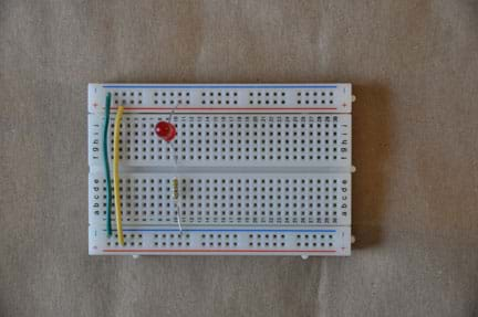
Figure 5: Breadboard with wires connecting positive and negative terminals and an LED light. - Ask students why their LED did not light up. (Answer: No power source is connected to the breadboard.)
- Show students the battery packs. Ask them which wires they think go to the positive and negative terminals. (Answer: black = negative; red=positive.) Hand out the battery packs and have students hook them up (see Figure 6).
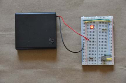
Figure 6: Breadboard with all connections. - Now that the entire circuit is hooked up, have students complete their VOC sensor worksheets.
- Remind students to bring in VOC sources from home.
Day 2
Before the students arrive: 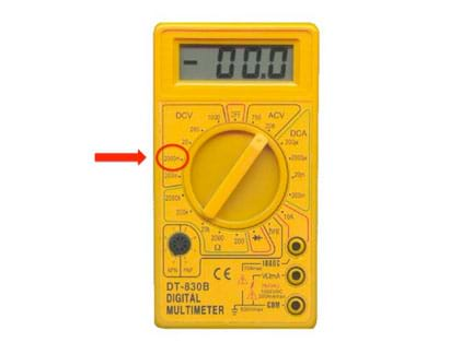
- Fill the buckets half full with water.
- Set up the VOC sensors, and connect the multimeters to either side of the resistor in terminal 4 (the terminal that connects the VOC sensor to the negative row). Turn the dial on the multimeter to 2000m (DCV), as shown in Figure 7.
- Copy the headings for the chart in Figure 8 onto the board. You will probably need more than 3 groups (students should complete the activity in the same groups as Day 1).
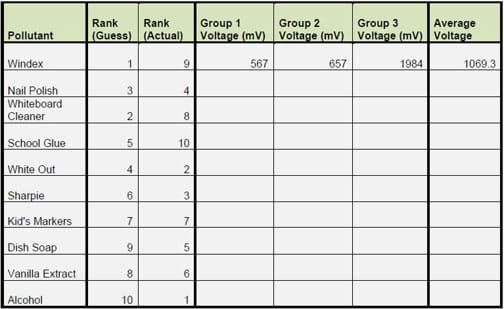
Figure 8: Pollutant Chart
With the students:
- Collect the VOC test sources from the classroom and students' homes. (It is fun to test and compare regular products to non-toxic products, such as Sharpies or white board markers to non-toxic markers, or regular glue to non-toxic glue, or regular paint to low-VOC paint.)
- Ask students to vote on which sources they think will pollute the most (meaning they will cause the measured voltage to rise the highest).
- Based on student predictions, tank the pollutants from highest polluter to lowest, and record the rankings in the chart on the board.
- Give students the following instructions for testing the VOC samples:
- Have one student from each group come up to the front of the class to get a sponge that contains the first pollutant on the list (in the example in Figure 8, this is Windex). Have them wait in line until they get their sponges (this may not apply to older students). Place a small amount of each pollutant on each sponge. Make sure not to put too much of any liquid pollutant (such as dish soap) on a sponge, to ensure that the pollutants do not drip on the VOC sensors.
- Have students take the sponges back to their desks, so each group can place a sponge about one-half inch above the sensor. DO NOT touch the sensor with the sponge. Make sure the pollutants do not drip onto the VOC sensor, either.
- When students place their sponges above the sensors, have them watch the numbers on their multimeters. Expect the numbers (voltage values) to up (see Activity Scaling for an explanation of the sensor function). Have them watch for the the highest number they see on the multimeter (the numbers will oscillate up and down).
- After groups determine the highest voltage value for their pollutant, have one student write that value on the board (from Figure 8, group 1 would write 567 in their column, in the "Windex" row). Another student, from the same group, should get back in line to get another pollutant. When the student reaches the front of the line, s/he should leave the used sponge in one of the buckets of water, and tell the teacher which pollutant s/he needs next (such as nail polish).
- Have students repeat these testing steps until they have tested every pollutant on the list.
- When students are finished testing, and have returned all the used sponges to the bucket of water, have them calculate the averages for each pollutant (for example, the Windex average is (567+657+1984) / 3). If students do not have the time or math skills to do this portion of this activity, calculate the averages for them.
- Rank the pollutants based on the voltage averages (highest voltage is number 1), and record the rankings in the Rank (actual) column. Compare the results to the students' predictions.
Vocabulary/Definitions
breadboard: A device for making simple electrical connections.
current: The flow of electrons.
ground-level ozone: A type of pollutant created when other pollutants (like VOCs) react with sunlight. Ozone is harmful to the human respiratory system.
resistance: Any part of a circuit that slows down the flow of electrons.
volatile organic compound: An organic chemical containing carbon that escapes into the air easily. Abbreviated as VOC. VOCs react with sunlight to produce ground-level ozone. VOCs are the most common type of indoor pollutant.
voltage: A difference in electrical potential.
Assessment
Pre-Activity Assessment
Discussion Questions: Ask students the following questions:
- What is a volatile organic compound?
- Can you describe voltage, current, and resistance?
Activity Embedded Assessment
Worksheet: Have students complete the attached Elementary and Middle VOC Worksheet or High School VOC Worksheet (depending on grade level). Review their answers to gauge their comprehension of the subject.
Post-Activity Assessment
Reflective Questions: Ask students the following questions:
- Why do you think different groups got different voltage values for the same pollutants? (Answers: the amount of pollutant placed on each sponge was not uniform, the distance each sponge was held from the sensor was not uniform, the battery packs each group had were not outputting uniform voltage, the sensors themselves are not uniform.) You can use this as a segway into talking to students about quality experiments and controlling variables.
- What do you think you can do to reduce your exposure to VOCs? (Answer: use non-VOC cleaners, don't use aerosol cosmetics/deodorant, go outside or open windows when using harsh chemicals, throw away old chemicals and store chemicals in a well-ventilated area, don't smoke, use a no VOC dry cleaner.)
Safety Issues
- This activity should not pose any safety issues, but remind students that it is not okay to play with electrical outlets due to their high voltage.
Troubleshooting Tips
If a sensor does not seem to be working, make sure that the breadboard has power (if it does, the LED should light up). If the LED is not lighting up, make sure the longer leg is in the positive terminal, the two positive lines are connected, the two negative lines are connected, the sensor notch is facing the center of the board, and that the four legs are in the correct columns. Also make sure the columns are connected to the correct terminals.
Activity Scaling
- For upper grades: Show the students the second slide in the PowerPoint presentation and explain how the sensor works (see Figure 9). Resistor 1 is a very small resistor attached to the positive and negative terminals. What happens when we attach the negative and positive terminals to each other with very little resistance? The wire heats up. This is similar to a short circuit, but just enough resistance is provided to stop the wire from burning up. This heats up the sensor, which needs to be warmed up to operate. At this warmer temperature, a surface chemistry reaction occurs with the VOCs, reducing the electrical resistance, resulting in higher readings on the multimeter.
Resistor 2 is connected to the positive terminal and to resistor 3, which is connected to the negative terminal. This setup is called connecting resistors in series, and the current flows from the negative terminal, through resistor 3, then through resistor 2 to the positive terminal.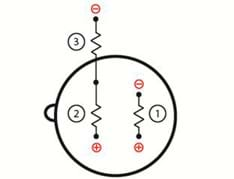
- Explain the science behind the activity to upper grades: Show the students the second Kirchoff's Voltage law states that the sum of voltages in a closed loop is equal to zero. In other words, if you add up the voltages across every element connected in series between the negative and positive terminals of a breadboard, the sum is equal to the voltage of the power source. In our case, the sum of the voltages across resistor 2 and 3 is equal to the voltage of the battery.
Vtotal = V2 + V3 , (Equation 1)
where Vtotal is the voltage supplied by the battery, and V2 and V3 are the voltages across resistors 2 and 3, respectively. For each resistor, Ohm's Law states that
Vresistor = iRresistor , (Equation 2)
Kirchoff's Current Law states that the current flowing into any node in a circuit is equal to the current flowing out of any node in a circuit. If you isolate the node between resistors 2 and 3, you can see that the current flowing across resistor 3 ( i3) must be the same as the current flowing across resistor 2 ( i2) (see Figure 10).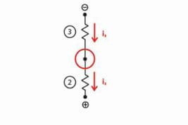
If you plug Equation 2 in to Equation 1, the result is
Vtotal = iR2 + iR3 , (Equation 3)
Since Vtotal is constant,
iR2 ∝ 1/iR3 , (Equation 4)
(iR2 is inversely proportional to iR3). By plugging Ohm's Law (V = iR) into Equation 4, we can conclude that
V2 ∝ 1/V3 , (Equation 5)
Equation 5 can be used to understand how the VOC sensor works. When VOCs come into contact with the surface of the sensor, a reaction occurs, and the resistance of resistor 2 decreases. Since V2 ∝ 1/V3 , if the voltage across resistor 2 decreases (which happens when the resistance decreases; refer to Ohm's Law: Vresistor = iR ), then voltage across resistor 3 increases. We can measure VOCs by measuring the voltage across resistor 3. When the voltage increases, it means that the sensor detects VOCs.
- For middle school students: Explain the function of the sensor using Equation 5 (without derivation) and Ohm's law.
- For students in grades 7-12: Consider explaining the function of the protoboards, and the function of the sensors and LED lights, then allowing students to wire the circuit without step-by-step instructions.
Subscribe
Get the inside scoop on all things Teach Engineering such as new site features, curriculum updates, video releases, and more by signing up for our newsletter!More Curriculum Like This

Students are introduced to the concepts of air pollution, air quality, and climate change. The three lesson parts (including the associated activities) focus on the prerequisites for understanding air pollution. First, students use M&M® candies to create pie graphs that express their understanding o...

Students identify types and sources of indoor air pollutants in their school and home environments. They evaluate actions that can be taken to reduce and prevent poor indoor air quality. Students also develop a persuasive peer-to-peer case against smoking with the goal to understand how language usa...

Students are introduced to the concepts of air pollution and technologies that engineers have developed to reduce air pollution. They develop an understanding of visible air pollutants with an incomplete combustion demonstration, a "smog in a jar" demonstration, construction of simple particulate ma...

Students learn the basics about the structure of the Earth’s atmosphere, the types of pollutants that are present in the atmosphere (primary, secondary, gas-phase compounds, particulate matter), and the importance of air quality research. They are also introduced to some engineering concepts such as...
References
An Introduction to Indoor Air Quality (IAQ): Volatile Organic Compounds (VOCs). Last updated March 22, 2011. U.S. Environmental Protection Agency. Accessed September 1, 2020. http://www.epa.gov/iaq/voc.html
Storr, Wayne. Kirchoffs Circuit Law, Tutorial 4 of 10. Last updated February 2012. Basic Electronics Tutorials by Wayne Storr. Accessed September 1, 2020. http://www.electronics-tutorials.ws/dccircuits/dcp_4.html
Copyright
© 2011 by Regents of the University of ColoradoContributors
Berkeley Almand; Mike HanniganSupporting Program
Integrated Teaching and Learning Program, College of Engineering and Applied Science, University of Colorado BoulderAcknowledgements
The contents of this digital library curriculum were developed under grants from the Fund for the Improvement of Postsecondary Education (FIPSE), U.S. Department of Education and National Science Foundation (GK-12 grant no. 0338326). However, these contents do not necessarily represent the policies of the Department of Education or National Science Foundation, and you should not assume endorsement by the federal government.
Last modified: September 1, 2020


User Comments & Tips